A view of an object is called a projection. By projecting multiple views from different directions in a systematic way, you can completely describe the shape of 3D objects.
There are certain standard practices that you must know to create sketches and documentation drawings that can be easily interpreted. For example, you need to know which views to show, how they should be oriented in your drawing, and how to represent key information such as edges, surfaces, vertices, hidden lines, centrelines, and other crucial details. The standard published in ANSI/ASME Y14.3 is common in the United States, where third- angle projection is used. Europe, Asia, and many other places use the first-angle projection system.
Views of a object:
A photograph shows an object as it appears to the observer but not necessarily as it is. It cannot describe the object accurately, no matter what distance or which direction it is taken from, because it does not show the exact shapes and sizes of the parts.
It would be impossible to create an accurate 3D model of an object using only a photograph for reference because it shows only one view. It is a 2D representation of a 3D object. Drawings are 2D representations as well, but unlike photos, they allow you to record sizes and shapes precisely. In engineering and other fields, a complete and clear description of the shape and size of an object is necessary to be sure that it is manufactured exactly as the designer intended. To provide this information about a 3D object, typically a number of systematically arranged views are used.
The system of views is called multiview projection. Each view provides certain definite information. For example, a front view shows the true shape and size of surfaces that are parallel to the front of the object. An example of a 3D object and its front view projection is shown in Figure 6.1. Figure 6.2 shows the same part and the six principal viewing directions. Figure 6.3 shows the same six views of a house.
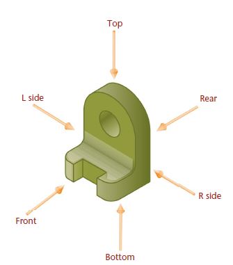
Six principle views

Multiview projection establishes views of an object projected on two or more planes of projection by using orthographic projection techniques. The result of multiview projection is a multiview drawing. A multiview drawing represents the shape of an object using two or more views. Consideration should be given to the choice and number of views used, so the surfaces of the object are shown in their true size and shape when possible.
It is generally easier to visualize a 3-D picture of an object than to visualize a 2-D drawing. In mechanical drafting, however, the common practice is to prepare completely dimensioned detail drawings using 2-D views known as multiviews.
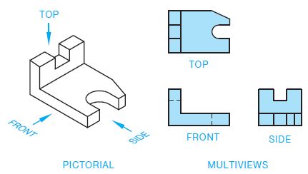
Figure shows an object represented by a 3-D drawing, also called a pictorial, and three 2-D views, or multiviews, also known as orthographic projection. The multiview method of drafting represents the shape description of the object.
FIRST-ANGLE PROJECTION
First-angle projection is commonly used in countries other than the United States. First-angle projection places the glass box in the first quadrant of Figure 8.16. Views are established by projecting surfaces of the object onto the surface of the glass box. In this projection arrangement, the object is between your line of sight and the projection plane, as shown in Figure 8.20. When the glass box in the first-angle projection quadrant is unfolded, the result is the multiview arrangement shown in Figure
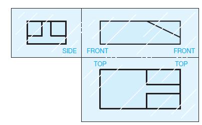
A first-angle projection drawing is identified by the first angle projection symbol.
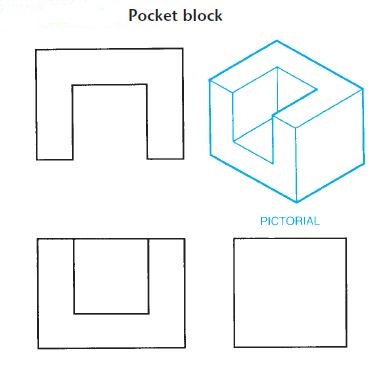
Figure 1
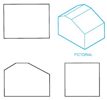
Figure 2
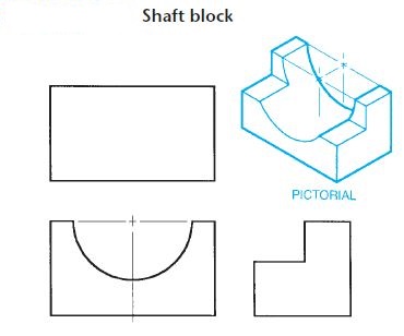
Figure 3
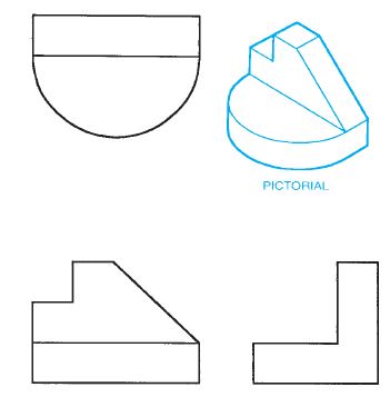
Figure 4
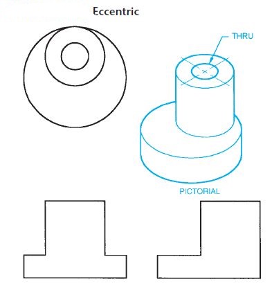
Figure 5
Third angle Projection:
The primary method of multiview projection described in this chapter is known as third-angle projection. Third-angle projection is the method of view arrangement commonly used in the United States. In the previous discussion on multiview projection, the object was placed in a glass box, so the sides of the glass box were parallel to the major surfaces of the object. Next, the object surfaces were projected onto the adjacent surfaces of the glass box. This gave the same effect as if your line of sight is perpendicular to the surface of the box and looking directly at the object, as shown in Figure 1. With the multiview concept in mind, assume an area of space is divided into four quadrants, as shown in Figure 2.
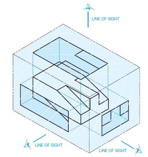
Figure 6
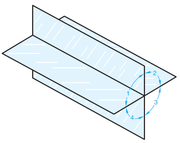
Figure 7
If the object is placed in any of these quadrants, the surfaces of the object are projected onto the adjacent planes. When placed in the first quadrant, the method of projection is known as first-angle projection. Projections in the other quadrants are termed second-, third-, and fourth-angle projections. Second- and fourth-angle projections are not used, though first- and third angle projections are common.
Third-angle projection is established when you take the glass box from Figure 1 and place it in quadrant 3 from Figure 2. Figure 3 shows the relationship of the glass box to the projection planes in the third-angle projection. In this quadrant, the projection plane is between your line of sight and the object. When the glass box in the third-angle projection quadrant is unfolded, the result is the multiview arrangement previously described and shown in Figure 4.
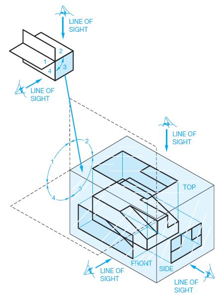
Figure 8
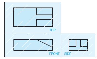
Figure 9
INTRODUCTION TO SECTIONAL VIEWS
Sectional views are also called sections, and the process of creating sections are referred to as sectioning. Sections are used to describe the interior portions of an object that are otherwise difficult to visualize. Interior features that are described using hidden lines are not as clear as if they are exposed for viewing as visible features. It is also a poor practice to dimension to hidden features. The sectional view allows you to expose the hidden features for dimensioning. Figure 10 shows an object in conventional multiview representation and using a sectional view. Notice how the hidden features are clarified in the sectional view.
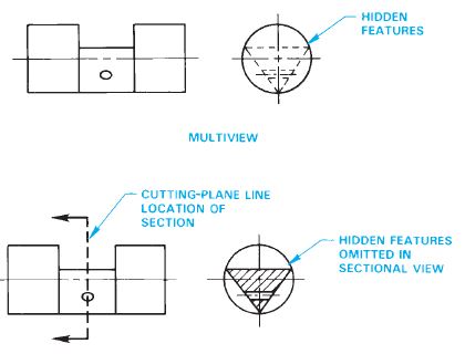
Figure 10
FULL SECTIONS
A full section is drawn when the cutting plane extends completely through the object, usually along a center plane as shown in Figure 6. The object shown in Figure 6 could have used two full sections to further clarify hidden features. In such a case, the cutting planes and related views are labelled (see Figure 11). The cutting-plane line can be omitted when the relationship between views is obvious. Confirm this practice with your instructor or employer. It is normally best to show the cutting-plane line for clarity.
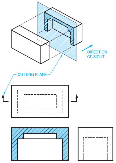
Figure 11
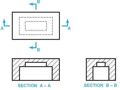
Figure 12
HALF SECTIONS
A half section is used when a symmetrical object requires sectioning. The cutting-plane line of a half section removes one quarter of the object. The advantage of a half section is the sectional view shows half of the object in section and the other half of the object as it normally appears in multiview without section. The name half section comes from the idea that only half of the sectional view is sectioned (see Figure 8). Notice that a centerline is used in the sectional view to separate the sectioned portion from the un-sectioned portion. Hidden lines are generally omitted from sectional views unless their use improves clarity.
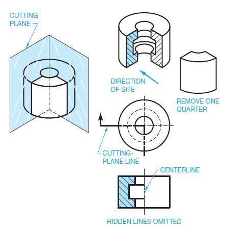
Figure 13
Offset section
Staggered interior features of an object are sectioned by allowing the cutting-plane line to offset through the features creating an offset section as shown in Figure 14. The cutting-plane line for an offset section is generally drawn using 908 turns where it offsets through the staggered features as shown in Figure 14a. Notice in Figure 9 that there is no line in the sectional view indicating a change in direction of the cutting-plane line. Normally, the cutting-plane line in an offset section extends completely through the object to display the location of the section clearly. A cutting plane line is always used when the cutting plane is bent or offset or when the sectional view is non-symmetrical. Figure14b shows how the segments of an offset cutting plane project from and are aligned with the center when used on a circular-shaped object. The portion of the cutting-plane line between offsets is drawn as an arc, with the arc center at the center of the object.
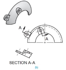
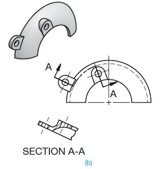
Figure 14
ALIGNED SECTIONS
Similar to the offset section, the aligned section cutting plane line staggers to pass through offset features of an object. Normally the change in direction of the cutting-plane line is less than 908 in an aligned section. When this section is taken, the sectional view is drawn as if the cutting plane is rotated to a plane perpendicular to the line of sight as shown in Figure 10. A cutting-plane line is always used when the cutting plane is bent or offset or when the sectional view is non-symmetrical.
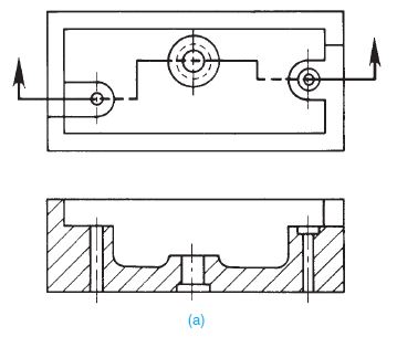
Figure 15
Reference Books
1. Madsen, D. P. and Madsen, D. A., (2016), “Engineering Drawing and design”,
Delmar Publishers Inc., USA
2. Bhatt, N. D., (2018), “Machine Drawing”, Chartor Publishing house, Anand, India
3. Dhawan, R. K., (2000), “A Textbook Of Engineering Drawing”, S. Chand, New
Delhi
4. Luzadder, W. J. and Duff, J. M., (1992), “The Fundamentals of Engineering
Drawing: With an Introduction to Interactive Computer Graphics for Design and
Production”, Peachpit Press, USA
5. Giesecke, F. E., Mitchell, A., Spencer, H. C., Hill, I. L., Loving, R. O., Dygon, J.
T., (1990), “Principles of engineering graphics”, McMillan Publishing, USA
6. Jensen, C., Helsel, J. D., Short, D. R., (2008), “Engineering Drawing and Design”,
McGraw-Hill International, Singapore