UNIT 1
INTRODUCTION TO ELECTROMAGNETIC THEORY AND OPTICS
Electrostatics, the study of electromagnetic phenomena that occur when there are no moving charges—i.e., after a static equilibrium has been established. Charges reach their equilibrium positions rapidly, because the electric force is extremely strong. The mathematical methods of electrostatics make it possible to calculate the distributions of the electric field and of the electric potential from a known configuration of charges, conductors, and insulators.
Conversely, given a set of conductors with known potentials, it is possible to calculate electric fields in regions between the conductors and to determine the charge distribution on the surface of the conductors.
The electric energy of a set of charges at rest can be viewed from the standpoint of the work required to assemble the charges; alternatively, the energy also can be considered to reside in the electric field produced by this assembly of charges. Finally, energy can be stored in a capacitor; the energy required to charge such a device is stored in it as electrostatic energy of the electric field.
All of us have the experience of seeing a spark or hearing a crackle when we take off our synthetic clothes or sweater, particularly in dry weather. This is almost inevitable with ladies garments like a polyester saree.
Have you ever tried to find any explanation for this phenomenon?
Another common example of electric discharge is the lightning that we see in the sky during thunderstorms. We also experience a sensation of an electric shock either while opening the door of a car or holding the iron bar of a bus after sliding from our seat. The reason for these experiences is discharge of electric charges through our body, which were accumulated due to rubbing of insulating surfaces. You might have also heard that this is due to generation of static electricity. Static means does not move or change with time.
Electrostatics deals with the study of forces, fields and potentials arising from static charges.
CHARGE DISTRIBUTION
We have seen so far the charge distributions have been discrete i.e. made up of individual point particles.
If a charge distribution is continuous rather than discrete, we can generalize the definition of the electric field. We simply divide the charge into infinitesimal pieces and treat each piece as a point charge.
We know that charge is quantized so there is no such thing as a truly continuous charge distribution. However, in most practical cases, the total charge creating the field involves such a huge number of discrete charges.
For simplicity we can safely ignore the discrete nature of the charge and consider it to be continuous. This is exactly the kind of approximation we make when we deal with a bucket of water as a continuous fluid rather than a collection of H2O molecules.
Continuous charge distribution: an arrangement of many discrete charges so closely spaced that the charge is treated as a continuum, resulting in a replacement of discrete sums with integrals.
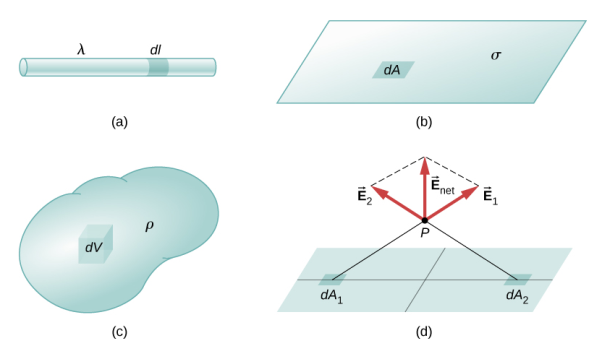
Distribution of charges
(a) Line charge density
(b) Surface charge density
(c) Volume charge density
(d) Some of the components of the total electric field cancel out, with the remainder resulting in a net electric field
Definitions of charge density:
(a) λ - Line charge: charge per unit length (linear charge density); units are coulombs per meter (C/m)
(b)  - Surface charge density: Charge per unit area; units are coulombs per square meter (C/m2)
(c)  - Volume charge density: Charge per unit volume; units are coulombs per cubic meter (C/m3)
1 Figure: Charge Distribution |
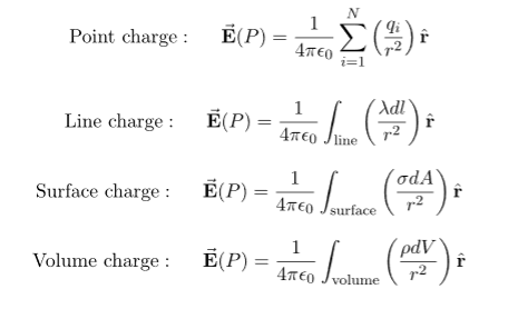
Some of the important result for electric field due to point charge, line charge density, surface charge density and volume charge density.
|
Note carefully the meaning of r in these equations: It is the distance from the charge element λdl,  ,
,  to the location of interest, P(x,y,z) (the point in space where you want to determine the field). However, don’t confuse this with the meaning of
  .
.
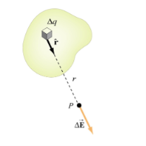
If the charge distribution is continuous, the potential at a point P can be found by summing over the contributions from individual differential elements of charge. dq
2 Figure: Continuous charge distribution Consider the charge distribution shown in Figure. Taking infinity as our reference point with zero potential, the electric potential at P due to dq is
Summing over contributions from all differential elements, we have
We established the relation between dV = - In Cartesian coordinates, E = Ex and dV = ( Ex dV = ( Ex dx+ Eydy + Ezdz This implies Ex = By introducing a differential quantity called the “del (gradient) operator”
The electric field can be written as
Notice that ∇ operates on a scalar quantity (electric potential) and results in a vector quantity (electric field). Mathematically, we can think of In the case of gravity, if the gravitational potential increases when a mass is lifted a distance h, the gravitational force must be downward. If the charge distribution possesses spherical symmetry, then the resulting electric field is a function of the radial distance r, i.e. In this case, .dV=- Er dr. If V(r) is known, then
For example, the electric potential due to a point charge q is V = Using the above formula, the electric field is simply E = |
DIVERGENCE OF ELECTROSTATIC FIELD
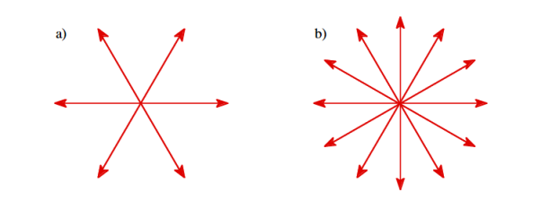
The electric field can be graphically represented using field lines. The direction of the field lines indicates the direction in which a positive test charge moves when placed in this field. The density of field lines per unit area is proportional to the strength of the electric field. Field lines originate on positive charges and terminate on negative charges. Field lines can never cross since if this would occur, the direction of the electric field at that particular point would be undefined. Examples of field lines produced by positive point charges are shown in Figure
3 Figure: a) Electric field lines generated by a positive point charge with charge q. b) Electric field lines generated by a positive point charge with charge 2q. The flux of electric field lines through any surface is proportional to the number of field lines passing through that surface. Consider for example a point charge q located at the origin. The electric flux
Since the number of field lines generated by the charge q depends only on the magnitude of the charge, any arbitrarily shaped surface that encloses q will intercept the same number of field lines. Therefore the electric flux through any surface that encloses the charge q is equal to q/
We thus conclude that for an arbitrary surface and arbitrary charge distribution
where Qenclosed is the total charge enclosed by the surface. This is called Gauss's law. Since this equation involves an integral it is also called Gauss's law in integral form. Using the divergence theorem the electric flux
We can also rewrite the enclosed charge Qencl in terms of the charge density ρ
Gauss's law can thus be rewritten as
Since we have not made any assumptions about the integration volume this equation must hold for any volume. This requires that the integrands are equal:
This equation is called Gauss's law in differential form. This is the required expression for divergence of electric field. Divergence is the outflow of flux from a small closed surface area (per unit volume) as volume shrinks to zero.
|
Physical Interpretation of the Divergence
For an electric field:∇·E= ρ/ε, that is there are sources of electric field. Consider a vector field F that represents a fluid velocity: The divergence of F at a point in a fluid is a measure of the rate at which the fluid is flowing away from or towards that point.
A positive divergence is indicating a flow away from the point. ƒPhysically divergence means that either the fluid is expanding or that fluid is being supplied by a source external to the field. ƒ The lines of flow diverge from a source and converge to a sink.
If there is no gain or loss of fluid anywhere then div F= 0. Such a vector field is said to be solenoidal.
Air leaving a punctured tire: Divergence is positive, as closed surface (tire) exhibits net outflow.
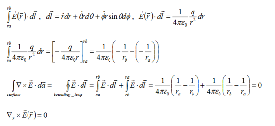
CURL OF ELECTROSTATIC FIELD For a point charge q placing at the origin, the electric field is: E = The curl calculation by integration:
By superposition rule:
The curl calculation by differentiation:
|
Physical Interpretation of the Curl
Consider a vector field F that represents a fluid velocity:
The curl of F at a point in a fluid is a measure of the rotation of the fluid.
If there is no rotation of fluid anywhere then ∇x F= 0. Such a vector field is said to be irrotational or conservative.
An electrostatic field (denoted by E) has the property ∇xE= 0, an irrotational (conservative) field.
LAPLACE’S AND POISSON’S EQUATIONS FOR ELECTROSTATIC POTENTIAL
A useful approach to the calculation of electric potentials is to relate that potential to the charge density which gives rise to it. The electric field is related to the charge density by the divergence relationship
 =
= 
E = Electric field
 = Charge density
 = Permittivity
and the electric field is related to the electric potential by a gradient relationship
E = 
Therefore the potential is related to the charge density by Poisson's equation
 =
=  2V =
2V = 
In a charge-free region of space, this becomes Laplace's equation
 2V = 0
This mathematical operation, the divergence of the gradient of a function, is called the Laplacian. Expressing the Laplacian in different coordinate systems to take advantage of the symmetry of a charge distribution helps in the solution for the electric potential V.
For example, if the charge distribution has spherical symmetry, you use the Laplacian in spherical polar coordinates.
Since the potential is a scalar function, this approach has advantages over trying to calculate the electric field directly. Once the potential has been calculated, the electric field can be computed by taking the gradient of the potential.
UNIQUENESS THEOREMS
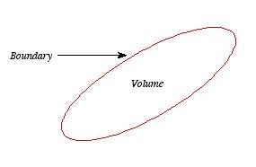
Consider a volume (see Figure 3.2) within which the charge density is equal to zero. Suppose that the value of the electrostatic potential is specified at every point on the surface of this volume. The first uniqueness theorem states that in this case the solution of Laplace's equation is uniquely defined.
4 Figure First Uniqueness Theorem |
To proof the first uniqueness theorem we will consider what happens when there are two solutions V1 and V2 of Laplace's equation in the volume shown in Figure. Since V1 and V2 are solutions of Laplace's equation we know that
 =0
=0
 =0
=0
Since both V1 and V2 are solutions, they must have the same value on the boundary. Thus V1 = V2 on the boundary of the volume. Now consider a third function V3, which is the difference between V1 and V2
 =
= -
-
The function V3 is also a solution of Laplace's equation. This can be demonstrated easily:
 =
= -
-  =0
=0
The value of the function V3 is equal to zero on the boundary of the volume since V1 = V2 there. However, property 2 of any solution of Laplace's equation states that it can have no local maxima or minima and that the extreme values of the solution must occur at the boundaries. Since V3 is a solution of Laplace's equation and its value is zero everywhere on the boundary of the volume, the maximum and minimum value of V3 must be equal to zero. Therefore, V3 must be equal to zero everywhere. This immediately implies that
V1 = V2
This proves that there can be no two different functions V1 and V2 that are solutions of Laplace's equation and satisfy the same boundary conditions. Therefore, the solution of Laplace's equation is uniquely determined if its value is a specified function on all boundaries of the region. This also indicates that it does not matter how you come by your solution: if (a) it is a solution of Laplace's equation, and (b) it has the correct value on the boundaries, then it is the right and only solution.
5 Figure |
The first uniqueness theorem can only be applied in those regions that are free of charge and surrounded by a boundary with a known potential (not necessarily constant). In the laboratory the boundaries are usually conductors connected to batteries to keep them at a fixed potential.
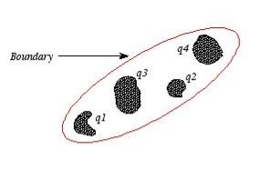
In many other electrostatic problems we do not know the potential at the boundaries of the system. Instead we might know the total charge on the various conductors that make up the system (note: knowing the total charge on a conductor does not imply a knowledge of the charge distribution ρ since it is influenced by the presence of the other conductors).
In addition to the conductors that make up the system, there might be a charge distribution ρ filling the regions between the conductors. For this type of system the first uniqueness theorem does not apply.
The second uniqueness theorem states that the electric field is uniquely determined if the total charge on each conductor is given and the charge distribution in the regions between the conductors is known.
The proof of the second uniqueness theorem is similar to the proof of the first uniqueness theorem. Suppose that there are two fields
where ρ is the charge density at the point where the electric field is evaluated. The surface integrals of
The difference between
satisfies the following equations:
Consider the surface integral of Therefore, The surface integral of
Since the surface integral of the surface integral of
The surface integral
0 = = -
where the volume integration is over all space between the conductors and the outer surface. Since |
The Biot Savart Law is an equation describing the magnetic field generated by a constant electric current. It relates the magnetic field to the magnitude, direction, length, and proximity of the electric current. Biot–Savart law is consistent with both Ampere’s circuital law and Gauss’s theorem. The Biot-Savart law is fundamental to magnetostatics, playing a role similar to that of Coulomb’s law in electrostatics.
The Biot-Savart law can be stated as:
Where, k is a constant, depending upon the magnetic properties of the medium and system of the units employed. In the SI system of unit,
Therefore, the final Biot-Savart law derivation is,
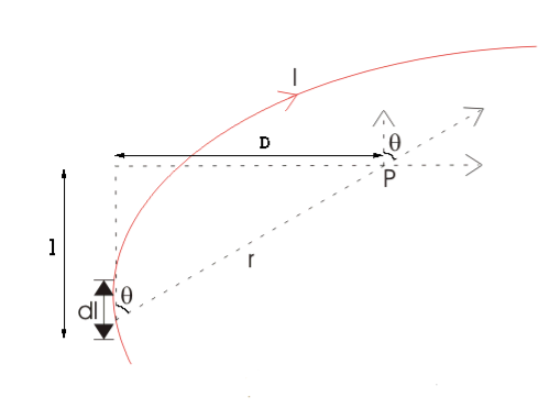
DERIVATION Let us consider a long wire carrying a current I and also consider a point p in the space. The wire is presented in the picture below, by red colour. Let us also consider an infinitely small length of the wire dl at a distance r from the point P as shown. Here, r is a distance-vector which makes an angle θ with the direction of current in the infinitesimal portion of the wire. If you try to visualize the condition, you can easily understand the magnetic field density at point P due to that infinitesimal length dl of the wire is directly proportional to current carried by this portion of the wire. As the current through that infinitesimal length of wire is the same as the current carried by the whole wire itself, we can write,
The magnetic field density at that point P due to that infinitesimal length dl of wire is inversely proportional to the square of the straight distance from point P to the center of dl. Mathematically we can write this as,
6 Figure
As θ be the angle between distance vector r and direction of current through this infinitesimal portion of the wire, the component of dl directly facing perpendicular to the point P is dlsinθ,
Now, combining these three statements, we can write,
This is the basic form of Biot Savart’ s Law Now, putting the value of constant k (which we have already introduced at the beginning of this article) in the above expression, we get
Here, μ0 used in the expression of constant k is absolute permeability of air or vacuum and its value is 4π
Now, flux density(B) at the point P due to the total length of the current-carrying conductor or wire can be represented as,
If D is the perpendicular distance of the point P from the wire, then
Now, the expression of flux density B at point P can be rewritten as,
As per the figure above,
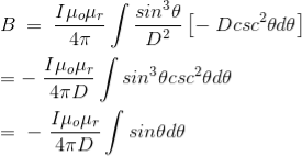
Finally, the expression of B comes as,
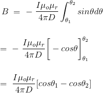
This angle θ depends upon the length of the wire and the position of the point P. Say for a certain limited length of the wire, angle θ as indicated in the figure above varies from θ1 to θ2. Hence, magnetic flux density at point P due to the total length of the conductor is,
Let’s imagine the wire is infinitely long, then θ will vary from 0 to π that is θ1 = 0 to θ2 = π. Putting these two values in the above final expression of Biot Savart law, we get,
This is nothing but the expression of Ampere’s Law. |
The static electric field E(x; y; z) such as the field of static charges obeys equations ∇. E =
The static magnetic field B(x; y; z) such as the field of steady currents obeys different equations
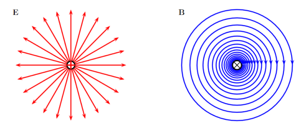
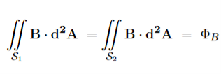
7 Figure Due to this difference, the magnetic field of long straight wire looks quite different from the electric field of a point charge or a linear charge. Later in these notes we will derive equations (3.2c) and (3.2d) from the Biot Savart Law. Let us explore some of their consequences. The zero-divergence equation (3.2c) is valid for any magnetic field, even if it is time-dependent rather than static. Physically, it means that there are no magnetic charges, otherwise we would have ∇.B Consequently, the magnetic field lines never begin or end anywhere in space; instead they form closed loops or run from in infinity to in infinity. The integral form of eq. (3.2c) follows by the Gauss theorem: the magnetic flux through any closed surface is zero
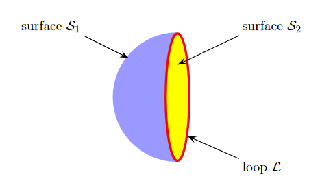
Consequently, any open surfaces S1,S2,……..spanning the same loop L have the same magnetic flux through them, for example
8 Figure
We shall this identity very useful for stating the Faraday's Law of magnetic induction. Now consider the curl equation
which is the differential form of the Ampere's Law. The integral form of the Ampere's Law obtains by the Stokes' theorem: For any closed loop L and any surface S spanning that loop,
………..(3.2e)
Where Inet [through L] is the net electric current flowing through the loop L. The integral form (3.2e) of the Ampere's Law is particularly convenient when the current flows through a wire or several wires; in this case all we need is to check which wire goes through the loop L and which does not, then add up the currents in the wires that do go through L and mind their directions. But it is also convenient for the volume currents flowing through thick conductors or for current sheets flowing on surfaces. As we know that the Ampere's Law applies only to the magnetic fields of steady currents. Otherwise, we need to use the more general Maxwell {Ampere Law, with an extra term for the time-dependent electric field. For simplicity we say that the original Ampere's Law is simply mathematically inconsistent unless the electric current has zero divergence, ∇J= 0.Indeed, the left hand side of the curl equation ∇. ( So we cannot have ( ∇.J= 0. As to the integral form (3.2e) of the Ampere's Law, we need a divergence-less current density J to make sure that the net current through the loop L is the same for any surface S spanning the loop; otherwise we simply cannot de ne the net current through L DERIVATION OF DIVERGENCE AND CURL OF MAGNETIC FIELD In general, when dealing with a current density J(x’) instead of a current I so (equation 1 of article 3.1) for the magnetic induction B(x) takes the form
Equation (1) can be expressed differently, since
but since
We get
If we set
Equation (5) is a mathematical statement on the inexistence of magnetic monopoles. Taking the curl of the B field, Using this identity
……….(5)
Solving this we get
This equation can be further simplified by using the divergence theorem
Since
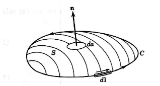
If we evaluate the integral on both sides of equation (7) over an open surface S of contour C (see Figure 2), we find
Figure 9: A magnetic induction is induced around a circuit C by a current density J through the open surface S bounded by C. and using Stokes’ theorem
c where I is the current passing through the surface. Equations (8) and (9) are mathematical representations of Ampère’s Law. |
Magnetization, Bound Currents, and the H Field. In magnetic materials, atoms and molecules may have non-zero average magnetic moments ⟨m⟩. Such magnetic moments are usually induced by external magnetic fields, but in permanent magnets they can remain long after the external field is switched off. One way or the other, the atomic/molecular magnetic moments lead to macroscopic magnetization. M= Here we shall explore the macroscopic magnetic field B(x; y; z) due to such magnetization. Let's start with the vector potential A(x; y; z) due to a single magnetic dipole m,
By the superposition principle, the vector potential of a bunch of magnetic dipoles is a sum of potentials like (2)
Likewise, for a continuous distribution of dipoles with macroscopic magnetization M(x; y; z),we have
To simplify this expression, we note that
and then integrate by parts:
Applying these formulae to the integrand of eq. (4), we arrive at
…………(7)
Moreover, the second term on the RHS can be rewritten as a surface integral, for any vector field T(r) and any volume V with surface S,
…………(8) Where n(r) is a unit vector normal to the surface S at point r. In the present context, M(r′)/
…………(9) which has the form of a vector potential created by the volume current Jb(r′) =∇ and the surface current Kb(r′) =M(r′) indeed, in terms of these current, the potential (9) becomes
The currents (10) and (11) are called the bound currents, by analogy with the bound charges in a dielectric.
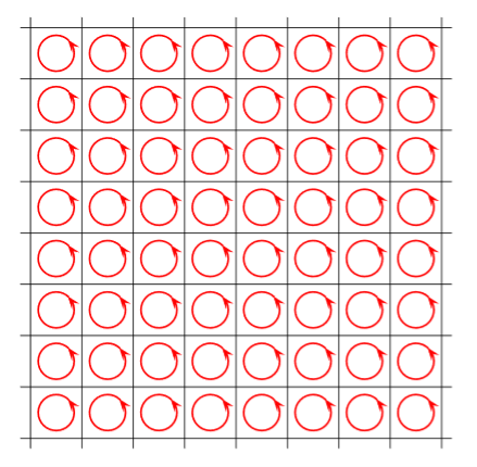
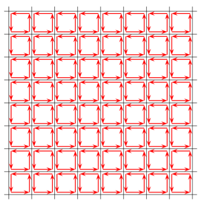
ORIGIN OF THE BOUND CURRENTS Physically, the bound currents on the surface of a magnetized material (and also in its volume for a non-uniform M) originate from the mis-cancellation of the microscopic currents inside the atoms which give rise to their magnetic moments. As a model of how this works, consider a large L m=a3M …………(1) The picture below shows a single slice of this cubic lattice along the (x; y) plane, or rather a small part of that slice:
Figure 10 The red loops here stand for the current loops creating the atomic magnetic moments m. We do not know the radii or even the shapes of these loops or the currents which flow through them; we do not even know if the currents are line currents or volume currents. But for our purposes all such details do not matter, all we care is the net magnetic moment m of each atom. As far as the macroscopic magnetic field B(r) is concerned, we may replace each atom with an a I = flowing around the 4 vertical sides of the cube. Here is the picture of such a cubic model, or rather, of a small part of a single slice of the cubic lattice:
Figure 11
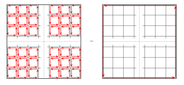
Inside each atom, the current flows counter clockwise. But when we look at the boundary between two neighbouring atoms, we immediately see that over that boundary, the currents of the two atoms flow in opposite directions. And since they have the same magnitude I=m/a2, they cancel each other. Thus, in the middle of the crystal all the atomic currents cancel each other and there is no net current. However, at the outer boundary of the crystal there is no cancellation.
Figure 12 Instead, there is un-cancelled current I=m/a2 flowing counter clockwise around the entire outer boundary of the crystal, or rather of single atomic layer of the crystal. The next layer on top of the layer shown on the above picture has a similar current, and so is every other layer, which makes for a surface current density. K = Over the 4 vertical sides of the whole magnetized cube. In vector notations, the surface current on each side of the cube is K = M where n is the unit vector normal to the side in question. The above toy model explains the physical origin of the surface bound current. It does not have a volume bound current since we assumed a uniform magnetization inside the magnetic material. To model a non-uniform magnetization we should give different atoms different magnetic moments m and hence different atomic currents. Consequently, at the boundary of two neighbouring atoms we would no longer have exact cancellation of their currents, and that would give rise to bound volume currents inside the bulk of the magnetized material. Assuming for simplicity that all atomic magnetic moments point in z directions but their magnitudes slowly depend on x and y coordinated of the atom, the net current on the boundary between two atoms neighbouring in x direction is
while on the boundary between two atoms neighbouring in y direction
Averaging these currents over the volume of the magnetized crystal, we get the volume bound current
…………(7) |
The magnetic effects in magnetic materials are due to atomic magnetic dipoles in the materials. These dipoles result from effective current loops of electrons in atomic orbits, from effects of electron spin & from the magnetic moments of atomic nuclei.
The electric currents in an atom are caused by orbital and spin motions of electrons and those of its nucleus. Since all these motions of charged particles form closed electric currents, they are equivalent to “magnetic dipoles”. When such dipoles are subjected to an external electric field, they experience a torque which tends to align their magnetic moments in the direction of the externally applied field.
SOME IMPORTANT DEFINITIONS
Magnetic dipole
Each tiny dimension of a magnetic material (or) atoms in magnetic materials is called magnetic dipole. This magnetic dipole produces magnetic moment depending on the alignment with respect to the applied magnetic field.
Magnetic flux (Ф)
It is defined as the amount of magnetic lines of forces passing perpendicularly through unit area of a given material. It is denoted by ‘Ф’
Ф=AB
Where A= Area of cross section of the material in m2
B = magnetic Induction in Wb/ m2
Units: Weber (Wb)
Intensity of Magnetization (M)
When a material is magnetized, it develops a net magnetic moment. The magnetic moment per unit volume is called Intensity of magnetization.
Magnetization (M) = 
Units: Amp/m
Magnetic Induction (B)
Magnetic induction at a point is defined as the force experienced by a unit North Pole Placed at that point. It is denoted by ‘B’i.e.
B =
Unit is weber / m2
Magnetizing field strength (H)
When a medium is exposed to a magnetic field of intensity ‘H’, it causes an induction ‘B’ in the medium .i.e. B H
B = μH
Where μ = absolute permeability of the medium. If the medium is air or vacuum B=μ0H
μ0=permeability of free space i.e. air or vacuum
μ0=4𝜋×10-7 H/m
Units for H: Amp /m
Permeability (μ)
It indicates with which the material allows magnetic lines of force to pass through it.
Or
It is the ability of the medium to pass magnetic lines of forces through it.
There are three Permeabilities i.e. μ1,μ0, μr
μ = μ0μr
Where μ = Absolute permeability of the medium
μ0 = Permeability of free space i.e. air or vacuum
μr = Relative permeability of the medium
Magnetic moment
Magnetic moment μm = (current) × (area of circulating orbit)
μm = (I) × (𝜋r2)
Units: Amp-m2
When the magnetic dipoles (atoms consisting of charged particles like protons & neutrons) undergo orbital motion (or) spin motion produces a magnetic moment. Since motion of charged particles is considered as closed electric current loops which in turn produces a magnetic moment.
Magnetic susceptibility (χ)
If H is the applied magnetizing field intensity and M is the amount of magnetization of the material,
Then χ = 
χ = 0 in vacuum
χ = +ve for paramagnetic and Ferro magnetic materials
χ = -ve for diamagnetic materials
Units: It has no units.
CLASSIFICATION OF MAGNETIC MATERIALS
Magnetic materials are classified as follows:
- Diamagnetic
- Paramagnetic
- Ferro magnetic
- Anti-Ferro magnetic
- Ferric magnetic or ferrites
DIAMAGNETIC
The orbital motion of electrons around the nucleus produces a magnetic field perpendicular to the plane of the orbit. Thus each electron orbit has finite orbital magnetic dipole moment. Since the orbital planes are oriented in random manner, the vector sum of magnetic moments is zero and there is no resultant magnetic moment for each atom.
In the presence of an external magnetic field, some electrons are speeded up and some are slowed down. The electrons whose moments were anti-parallel are speeded up according to Lenz’s law and this produces an induced magnetic moment in a direction opposite to the field. The induced moment disappears as soon as the external field is removed.
When placed in a non-uniform magnetic field, the interaction between induced magnetic moment and the external field creates a force which tends to move the material from stronger part to weaker part of the external field. It means that diamagnetic material is repelled by the field.
This action is called diamagnetic action and such materials are known as diamagnetic materials. Examples: Bismuth, Copper and Water etc.
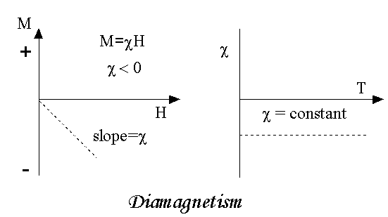
Diamagnetism is a fundamental property of all matter, although it is usually very weak. It is due to the non-cooperative behaviour of orbiting electrons when exposed to an applied magnetic field. Diamagnetic substances are composed of atoms which have no net magnetic moments (ie., all the orbital shells are filled and there are no unpaired electrons). However, when exposed to a field, a negative magnetization is produced and thus the susceptibility is negative. If we plot M vs H, we see
Figure 13 |
Note that when the field is zero the magnetization is zero. The other characteristic behaviour of diamagnetic materials is that the susceptibility is temperature independent. Some well-known diamagnetic substances, in units of 10-8 m3/kg, include:
Quartz (SiO2) -0.62
Calcite (CaCO3) -0.48
Water -0.90
The properties of diamagnetic materials are
- Magnetic susceptibility is negative.
- Relative permeability is slightly less than unity.
- The magnetic field lines are repelled or expelled by diamagnetic materials when placed in a magnetic field.
- Susceptibility is nearly temperature independent.
- Examples: Cu, Au, Zn, H20, Bi etc. organic materials
PARAMAGNETIC MATERIALS
In some magnetic materials, each atom or molecule has net magnetic dipole moment which is the vector sum of orbital and spin magnetic moments of electrons. Due to the random orientation of these magnetic moments, the net magnetic moment of the materials is zero.
In the presence of an external magnetic field, the torque acting on the atomic dipoles will align them in the field direction. As a result, there is net magnetic dipole moment induced in the direction of the applied field. The induced dipole moment is present as long as the external field exists.
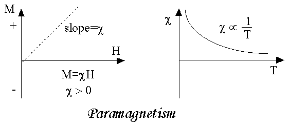
As we come to know this class of materials, some of the atoms or ions in the material have a net magnetic moment due to unpaired electrons in partially filled orbitals. One of the most important atoms with unpaired electrons is iron. However, the individual magnetic moments do not interact magnetically, and like diamagnetism, the magnetization is zero when the field is removed. In the presence of a field, there is now a partial alignment of the atomic magnetic moments in the direction of the field, resulting in a net positive magnetization and positive susceptibility.
Figure 14 |
In addition, the efficiency of the field in aligning the moments is opposed by the randomizing effects of temperature. This results in a temperature dependent susceptibility, known as the Curie Law.
At normal temperatures and in moderate fields, the paramagnetic susceptibility is small (but larger than the diamagnetic contribution). Unless the temperature is very low (<<100 K) or the field is very high paramagnetic susceptibility is independent of the applied field. Under these conditions, paramagnetic susceptibility is proportional to the total iron content. Many iron bearing minerals are paramagnetic at room temperature. Some examples, in units of 10-8 m3/kg, include:
Montmorillonite (clay) 13
Nontronite (Fe-rich clay) 65
Biotite (silicate) 79
Siderite (carbonate) 100
Pyrite (sulphide) 30
The paramagnetism of the matrix minerals in natural samples can be significant if the concentration of magnetite is very small. In this case, a paramagnetic correction may be needed.
The properties of paramagnetic materials are:
- Magnetic susceptibility is positive and small.
- Relative permeability is greater than unity.
- The magnetic field lines are attracted into the paramagnetic materials when placed in a magnetic field.
- Susceptibility is inversely proportional to temperature.
FERROMAGNETIC MATERIALS
An atom or a molecule in a ferromagnetic material possesses net magnetic dipole moment as in a paramagnetic material. A ferromagnetic material is made up of smaller regions, called ferromagnetic domain (Figure 3.27). Within each domain, the magnetic moments are spontaneously aligned in a direction. This alignment is caused by strong interaction arising from electron spin which depends on the inter-atomic distance. Each domain has net magnetisation in a direction. However the direction of magnetisation varies from domain to domain and thus net magnetisation of the specimen is zero.
In the presence of external magnetic field, two processes take place
1. the domains having magnetic moments parallel to the field grow in size
2. the other domains (not parallel to field) are rotated so that they are aligned with the field.
As a result of these mechanisms, there is a strong net magnetisation of the material in the direction of the applied field
When placed in a non-uniform magnetic field, the ferromagnetic materials will have a strong tendency to move from weaker to stronger part of the field. Materials which exhibit strong magnetism in the direction of applied field are called ferromagnetic materials.
When you think of magnetic materials, you probably think of iron, nickel or magnetite. Unlike paramagnetic materials, the atomic moments in these materials exhibit very strong interactions. These interactions are produced by electronic exchange forces and result in a parallel or antiparallel alignment of atomic moments. Exchange forces are very large, equivalent to a field on the order of 1000 Tesla, or approximately a 100 million times the strength of the earth's field.
The exchange force is a quantum mechanical phenomenon due to the relative orientation of the spins of two electrons.
Ferromagnetic materials exhibit parallel alignment of moments resulting in large net magnetization even in the absence of a magnetic field.
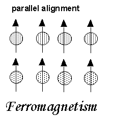 The elements Fe, Ni, and Co and many of their alloys are typical ferromagnetic materials.
Two distinct characteristics of ferromagnetic materials are their
(1) Spontaneous magnetization and
(2) Magnetic ordering temperature
Figure 15
Spontaneous Magnetization
The spontaneous magnetization is the net magnetization that exists inside a uniformly magnetized microscopic volume in the absence of a field. The 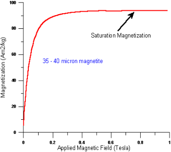 magnitude of this magnetization, at 0 K, is dependent on the spin magnetic moments of electrons.
A related term is the saturation magnetization which we can measure in the laboratory. The saturation magnetization is the maximum induced magnetic moment that can be obtained in a magnetic field (Hsat); beyond this field no further increase in magnetization occurs.
The difference between spontaneous
Figure 16
magnetization and the saturation magnetization has to do with magnetic
domains (more about domains later). Saturation magnetization is an intrinsic property, independent of particle size but dependent on temperature.
There is a big difference between paramagnetic and ferromagnetic susceptibility. As compared to paramagnetic materials, the magnetization in ferromagnetic materials is saturated in moderate magnetic fields and at high (room-temperature) temperatures:
| Hsat Tesla | T range (K) | χ 10-8m3/kg |
paramagnets | >10 | <<100 | ~50 |
ferromagnets | ~1 | ~300 | 1000-10000 |
The properties of ferromagnetic materials are:
- Magnetic susceptibility is positive and large.
- Relative permeability is large.
- The magnetic field lines are strongly attracted into the ferromagnetic materials when placed in a magnetic field.
- Susceptibility is inversely proportional to temperature.
ANTIFERROMAGNETISM
In the periodic table the only element exhibiting antiferromagnetism at room temperature is chromium. Antiferromagnetic materials are very similar to ferromagnetic materials but the exchange interaction between neighbouring atoms leads to the anti-parallel alignment of the atomic magnetic moments. Therefore, the magnetic field cancels out and the material appears to behave in the same way as a paramagnetic material. Like ferromagnetic materials these materials become paramagnetic above a transition temperature, known as the Neel temperature, TN. (Cr: TN=37ºC).
The properties of antiferromagnetic materials are:
- They have permanent magnetic dipoles
- They do not possess permanent magnetic dipole moment. Since in the absence of field they have no spontaneous magnetization due to anti parallel spin
- The relative permeability μr>1
- Susceptibility χ is small but negative
- 𝜒depends on temperature
FERRIMAGNETISM
Ferrimagnetism is only observed in compounds, which have more complex crystal structures than pure elements. Within these materials the exchange interactions lead to parallel alignment of atoms in some of the crystal sites and anti-parallel alignment of others. The material breaks down into magnetic domains, just like a ferromagnetic material and the magnetic behaviour is also very similar, although ferrimagnetic materials usually have lower saturation magnetisations. For example in Barium ferrite (BaO.6Fe2O3) the unit cell contains 64 ions of which the barium and oxygen ions have no magnetic moment, 16 Fe3+ ions have moments aligned parallel and 8 Fe3+ aligned anti-parallel giving a net magnetisation parallel to the applied field, but with a relatively low magnitude as only ⅛ of the ions contribute to the magnetisation of the material.
The properties of ferrimagnetic materials are:
- They have permanent magnetic dipoles.
- They possess permanent magnetic diploe moment. Also in the absence of field they have spontaneous magnetization. Since spin is anti-parallel but of different magnitudes
- The relative permeability μr>>1
- Susceptibility is large and positive
- 𝜒 depend on temperature
Faraday’s law of electromagnetic induction (referred to as Faraday’s law) is a basic law of electromagnetism predicting how a magnetic field will interact with an electric circuit to produce an electromotive force (EMF). This phenomenon is known as electromagnetic induction.
Faraday’s law states that a current will be induced in a conductor which is exposed to a changing magnetic field. Lenz’s law of electromagnetic induction states that the direction of this induced current will be such that the magnetic field created by the induced current opposes the initial changing magnetic field which produced it. The direction of this current flow can be determined using Fleming’s right-hand rule.
Let us understand Faraday’s law by faraday‘s experiment.
FARADAY’S EXPERIMENT
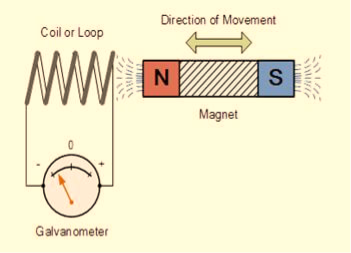
In this experiment, Faraday takes a magnet and a coil and connects a galvanometer across the coil. At starting, the magnet is at rest, so there is no deflection in the galvanometer i.e. the needle of the galvanometer is at the center or zero position. When the magnet is moved towards the coil, the needle of the galvanometer deflects in one direction.
Figure 16
|
When the magnet is held stationary at that position, the needle of galvanometer returns to zero position. Now when the magnet moves away from the coil, there is some deflection in the needle but opposite direction, and again when the magnet becomes stationary, at that point respect to the coil, the needle of the galvanometer returns to the zero position.
Similarly, if the magnet is held stationary and the coil moves away, and towards the magnet, the galvanometer similarly shows deflection. It is also seen that the faster the change in the magnetic field, the greater will be the induced EMF or voltage in the coil.
Let us take a look at the following table. This table is showing the observation of faraday’s experiment.
Position of magnet | Deflection in galvanometer |
Magnet at rest | No deflection in the galvanometer |
Magnet moves towards the coil | Deflection in galvanometer in one direction |
Magnet is held stationary at same position (near the coil) | No deflection in the galvanometer |
Magnet moves away from the coil | Deflection in galvanometer but in the opposite direction |
Magnet is held stationary at the same position (away from the coil) | No deflection in the galvanometer |
CONCLUSION
From this experiment, Faraday concluded that whenever there is relative motion between a conductor and a magnetic field, the flux linkage with a coil changes and this change in flux induces a voltage across a coil.
Michael Faraday formulated two laws on the basis of the above experiments. These laws are called Faraday’s laws of electromagnetic induction.
FARADAY’S FIRST LAW
Any change in the magnetic field of a coil of wire will cause an emf to be induced in the coil. This emf induced is called induced emf and if the conductor circuit is closed, the current will also circulate through the circuit and this current is called induced current.
Method to change the magnetic field:
- By moving a magnet towards or away from the coil
- By moving the coil into or out of the magnetic field
- By changing the area of a coil placed in the magnetic field
- By rotating the coil relative to the magnet
FARADAY’S SECOND LAW
It states that the magnitude of emf induced in the coil is equal to the rate of change of flux that linkages with the coil. The flux linkage of the coil is the product of the number of turns in the coil and flux associated with the coil.
FARADAY LAW FORMULA Consider, a magnet is approaching towards a coil. Here we consider two instants at time T1 and time T2. Coil has N number of turns. Flux linkage with the coil at time,
Flux linkage with the coil at time,
Change in flux linkage,
Let this change in flux linkage be,
So, the Change in flux linkage
Now the rate of change of flux linkage
Take derivative on right-hand side we will get as N is number of turns of coils which is constant so taken out of derivative, we get
The rate of change of flux linkage
Where E is induced emf. But according to Faraday’s law of electromagnetic induction, the rate of change of flux linkage is equal to induced emf.
Considering Lenz’s Law Where:
|
FACTORS ON WHICH INDUCED EMF DEPEND
- By increasing the number of turns in the coil i.e. N, from the formulae derived above it is easily seen that if the number of turns in a coil is increased, the induced emf also gets increased.
- By increasing magnetic field strength i.e. B surrounding the coil- Mathematically, if magnetic field increases, flux increases and if flux increases emf induced will also get increased. Theoretically, if the coil is passed through a stronger magnetic field, there will be more lines of force for the coil to cut and hence there will be more emf induced.
- By increasing the speed of the relative motion between the coil and the magnet – If the relative speed between the coil and magnet is increased from its previous value, the coil will cut the lines of flux at a faster rate, so more induced emf would be produced.
APPLICATIONS OF FARADAY’S LAW
Faraday law is one of the most basic and important laws of electromagnetism. This law finds its application in most of the electrical machines, industries, and the medical field, etc.
- Power transformers function based on Faraday’s law
- The basic working principle of the electrical generator is Faraday’s law of mutual induction.
- The Induction cooker is the fastest way of cooking. It also works on the principle of mutual induction. When current flows through the coil of copper wire placed below a cooking container, it produces a changing magnetic field. This alternating or changing magnetic field induces an emf and hence the current in the conductive container, and we know that the flow of current always produces heat in it.
- Electromagnetic Flow Meter is used to measure the velocity of certain fluids. When a magnetic field is applied to an electrically insulated pipe in which conducting fluids are flowing, then according to Faraday’s law, an electromotive force is induced in it. This induced emf is proportional to the velocity of fluid flowing.
- From bases of Electromagnetic theory, Faraday’s idea lines of force is used in well-known Maxwell’s equations. According to Faraday’s law, change in magnetic field gives rise to change in electric field and the converse of this is used in Maxwell’s equations.
- It is also used in musical instruments like an electric guitar, electric violin, etc.
Lenz’s law states that the direction of the current induced in a conductor by a changing magnetic field is such that the magnetic field created by the induced current opposes the initial changing magnetic field which produced it.
Lenz’s Law is named after the German scientist H. F. E. Lenz in 1834.
To better understand Lenz’s law, let us consider two cases:
Case 1: When a magnet is moving towards the coil.
Figure 17 |
When the north pole of the magnet is approaching towards the coil, the magnetic flux linking to the coil increases. According to Faraday’s law of electromagnetic induction, when there is a change in flux, an EMF, and hence current is induced in the coil and this current will create its own magnetic field.
Now according to Lenz’s law, this magnetic field created will oppose its own or we can say opposes the increase in flux through the coil and this is possible only if approaching coil side attains north polarity, as we know similar poles repel each other. Once we know the magnetic polarity of the coil side, we can easily determine the direction of the induced current by applying right hand rule. In this case, the current flows in the anticlockwise direction.
Case 2: When a magnet is moving away from the coil
Figure 18
|
When the north pole of the magnet is moving away from the coil, the magnetic flux linking to the coil decreases. According to Faraday’s law of electromagnetic induction, an EMF and hence current is induced in the coil and this current will create its own magnetic field.
Now according to Lenz’s law, this magnetic field created will oppose its own or we can say opposes the decrease in flux through the coil and this is possible only if approaching coil side attains south polarity, as we know dissimilar poles attract each other. Once we know the magnetic polarity of the coil side, we can easily determine the direction of the induced current by applying right hand rule. In this case, the current flows in a clockwise direction.
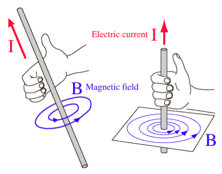
Note that for finding the directions of magnetic field or current, use the right-hand thumb rule i.e. if the fingers of the right hand are placed around the wire so that the thumb points in the direction of current flow, then the curling of fingers will show the direction of the magnetic field produced by the wire.
Figure 19
|
Lenz’s law can be stated as follows:
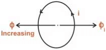
- If the magnetic flux Ф linking a coil increases, the direction of current in the coil will be such that it will oppose the increase in flux and hence the induced current will produce its flux in a direction as shown below (using Fleming’s right-hand thumb rule)
Figure 20
|
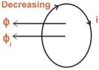
- If magnetic flux Ф linking a coil is decreasing, the flux produced by the current in the coil is such, that it will aid the main flux and hence the direction of current is as shown below.
Figure 21
|
LENZ’S LAW FORMULA
Lenz’s law states that when an EMF is generated by a change in magnetic flux according to Faraday’s Law, the polarity of the induced EMF is such, that it produces an induced current whose magnetic field opposes the initial changing magnetic field which produced it
The negative sign used in Faraday’s law of electromagnetic induction, indicates that the induced EMF (ε) and the change in magnetic flux (δΦB) have opposite signs. The formula for Lenz’s law is shown below

Where:
- ε = Induced emf
- δΦB = change in magnetic flux
- N = Number of turns in coil
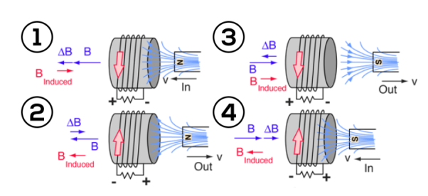
Lenz’s law can also be understood as follow. We already know that when a current is induced by a magnetic field, the magnetic field that this induced current produces will create its own magnetic field. This magnetic field will always be such that it opposes the magnetic field that originally created it. In the example below, if the magnetic field “B” is increasing – as shown in (1) – the induced magnetic field will act in opposition to it.
When the magnetic field “B” is decreasing – as shown in (2) – the induced magnetic field will again act in opposition to it. But this time ‘in opposition’ means that it is acting to increase the field – since it is opposing the decreasing rate of change.
Lenz’s law is based on Faraday’s law of induction. Faraday’s law tells us that a changing magnetic field will induce a current in a conductor. Lenz’s law tells us the direction of this induced current, which opposes the initial changing magnetic field which produced it. This is signified in the formula for Faraday’s law by the negative sign (‘–’).

Figure 22 |
This change in the magnetic field may be caused by changing the magnetic field strength by moving a magnet towards or away from the coil, or moving the coil into or out of the magnetic field. In other words, we can say that the magnitude of the EMF induced in the circuit is proportional to the rate of change of flux.


LENZ’S LAW AND CONSERVATION OF ENERGY
Lenz’s law obeys Newton’s third law of motion (i.e. to every action there is always an equal and opposite reaction) and the conservation of energy (i.e. energy may neither be created nor destroyed and therefore the sum of all the energies in the system is a constant).
To obey the conservation of energy, the direction of the current induced via Lenz’s law must create a magnetic field that opposes the magnetic field that created it. In fact, Lenz’s law is a consequence of the law of conservation of energy.
If the magnetic field created by the induced current is the same direction as the field that produced it, then these two magnetic fields would combine and create a larger magnetic field. This combined larger magnetic field would, in turn, induce another current within the conductor twice the magnitude of the original induced current.
And this would, in turn, create another magnetic field that would induce yet another current. And so on. So we can see that if Lenz’s law did not dictate that the induced current must create a magnetic field that opposes the field that created it – then we would end up with an endless positive feedback loop, breaking the conservation of energy (since we are effectively creating an endless energy source).
Lenz’s law also obeys Newton’s third law of motion (i.e to every action there is always an equal and opposite reaction). If the induced current creates a magnetic field that is equal and opposite to the direction of the magnetic field that creates it, then only it can resist the change in the magnetic field in the area. This is in accordance with Newton’s third law of motion.
MAXWELL EQUATIONS Maxwell equations are of fundamental importance since they describe the whole of classical electromagnetic phenomena. From a classical perspective, light can be described as waves of electromagnetic radiation. As such, Maxwell equations are very useful to illustrate a number of the characteristics of light including polarization. We are just to stating these equations without derivation. Since our goal is simply to apply them, the usual approach will be followed. Maxwell’s four equations are given by ∇·E = ρ/ε0 (1) ∇×E = −∂B/∂t (2) ∇×H = J + ∂D/∂t (3) ∇·B = 0 (4) These equations illustrate the unique coexistence in nature of the electric field and the magnetic field. The first two equations give the value of the given flux through a closed surface, and the second two equations give the value of a line integral around a loop. In this notation, ∇=(∂/∂x, ∂/∂y, ∂/∂z) E is the electric vector B is the magnetic induction ρ is the electric charge density j is the electric current density ε0 is the permittivity of free space c is the speed of light.
In addition to Maxwell equations, the following identities are useful:
J = σE (5) D = εE (6) B = μH (7)
Here, D is the electric displacement H is the magnetic vector σ is the specific conductivity ε is the dielectric constant (or permittivity) μ is the magnetic permeability In the Gaussian systems of units, Maxwell equations are given in the form of ∇·B=0 (8) ∇·E=4πρ (9) ∇×H=(1/c)(∂D/∂t+4πj) (10) ∇×E=−(1/c)(∂B/∂t) (11)
Free space or non-conducting medium. We know that non conducting medium means no current so conductivity is zero i.e. σ=0 So current density J=σE will also become zero as σ=0 Also free space means no charges which leads to ρ=0. These points mentioned below. (a) No condition current i.e σ=0, thus J=0 ( J=σE) (b) No charges (i.e ρ=0) For the case of no charges or currents, that is, j = 0 and ρ = 0, and a homogeneous medium. Using these the Maxwell equation can rewritten as ∇.D=0 or ∇.E=0 as ρ=0 (12) ∇ x E= -dB/dt or ∇ x E= -μ dH/dt because B = μH (13) ∇ x H=d D/dt or ∇ x H = ε dE/dt (J=0) and D = εE (14) ∇.B=0 (15) Now taking curl of second Maxwell’s equation (13) ,we get ∇ x(∇ x E)=- μ d/dt (∇ x H) Applying standard vector identity, that is [∇ *(∇*E)=∇(∇.E)-∇2E] on left hand side of above equation, we get ∇ (∇ .E)-∇2E= -μ d/dt (∇ x H) (16) Substituting equations (13) and (14) in equations (16) ,we get -∇2E= – με d/dt (dE/dt) Or ∇2E=με d 2 E/dT2 (17) Equation (17) is the required wave equation in terms of electric field intensity, E for free space . This is the law that E must obey. WAVE EQUATION IN TERMS OF MAGNETIC FIELD INTENSITY, H Take curl of fourth Maxwell’s equation(14) ,we get ∇x(∇xH)=ε d/dt(∇xE) Applying standard vector identity that is [∇*(∇*H)=∇ (∇.H)-∇2H] On left side of above equation , we get ∇(∇.H)-∇2H= ε d/dt(∇xE) (18) Substituting equations (14) and (13) in equation(18) ,we get -∇2H= – μεd/dt(dH/dt) Or ∇2H=με d2H/dt2 (19) Equations (19) is the required wave equation in terms of magnetic field intensity, H and this is the law that H must obey For vacuum μ=μ0 and ε=ε0, equations (17) and (19) will become ∇2 E=μ0ε0 d2E/dt2 (20) And ∇2H= μ0ε0 d2H/dt2 (21)
This leads to an expression for the velocity of propagation From equation both equations (20) and (21) have the form of the general wave equation for a wave
(x,t) traveling in the x direction with speed v. Equating the speed with the coefficients, we derive the speed of electric and magnetic waves, which is a constant that we symbolize with “c” It is useful to note that in vacuum c2=1/ε0μ0 Where μ0 is the permeability of free space
|
Motion of a charged particle in the simultaneous presence of both electric and magnetic fields has variety of manifestations ranging from straight line motion to the cycloid and other complex motion. Both electric and magnetic fields impart acceleration to the charged particle. But, there is a qualification for magnetic field as acceleration due to magnetic field relates only to the change of direction of motion.
Magnetic force being always normal to the velocity of the particle tends to move the particle about a circular trajectory. On the other hand, electric force is along electric field and is capable to bring about change in both direction and magnitude depending upon the initial direction of velocity of the charged particle with respect to electric field. If velocity and electric vectors are at an angle then the particle follows a parabolic path.
One of the important orientations of electric and magnetic fields is referred as “crossed fields”. We use the term “crossed fields” to mean simultaneous presence of electric and magnetic fields at right angle. The behaviour of charged particles such as electrons under crossed fields has important significance in the study of electromagnetic measurement and application (determination of specific charge of electron, cyclotron etc.).
Before we proceed, we should understand that elementary charged particles have mass of the order of 10−28 kg or less. Therefore, even small electric or magnetic force is capable to generate very high acceleration of the order of 1012 m/s2 or more.
Charged particle is moving along parallel electric and magnetic field
The velocity, electric and magnetic vectors are in in the same direction. Let they are aligned along x-axis. Since magnetic field and velocity vectors are parallel, there is no magnetic force.
FM=v0qBsin0°=0
Where v0 is initial speed of the particle. The charged particle is, however, acted upon by electric field. It is accelerated or decelerated depending on the polarity of charge and direction of electric field.
Considering positive charge, the electric force on the charge is given as
FE=qE
The acceleration of particle carrying charge in x-direction is :
⇒ay= 
The displacement along x-axis after time “t” is given by :
x=v0t+ ayt2
ayt2
x=v0t+ t2
t2
Charge is moving perpendicular to parallel electric and magnetic fields
Let electric and magnetic fields align along y-direction and velocity vector is aligned along positive x-direction. Let the charge be positive and initial velocity be v0.
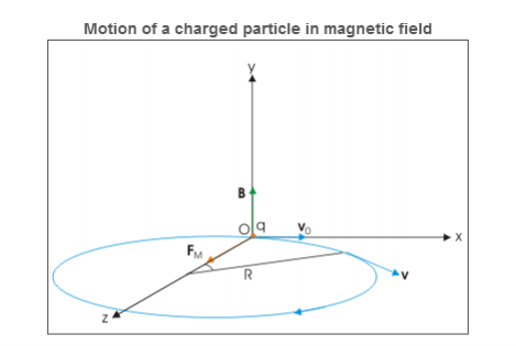
In this case, velocity and magnetic field vectors are perpendicular to each other. Applying Right hand vector cross product rule, we determine that magnetic force is acting in positive z-direction. If electric field is not present, then the particle revolves along a circle in xz plane as shown in the figure below.
Figure 23
|
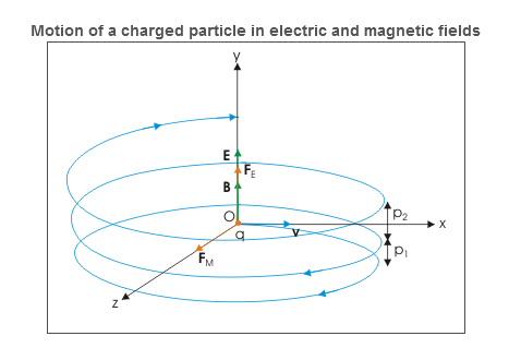
However, electric field in y-direction imparts acceleration in that direction. The particle, therefore, acquires velocity in y-direction and resulting motion is a helical motion. But since particle is accelerated in y –direction, the linear distance between consecutive circular elements of helix increases. In other words, the resulting motion is a helical motion with increasing pitch.
Figure 24
|
The radius of each of the circular element and other periodic attributes like time period, frequency and angular frequency are same as for the case of circular motion of charged particle in perpendicular to magnetic field.
R = 
T = 
ν= 
ω=αB
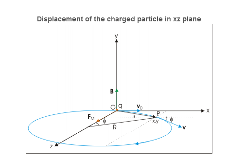
Velocity of the charged particle The velocity of the particle in xz is: v=vxi + vzj=v0cosωt i+ vosinωt k ⇒v= v0cosωt i+ vosinωt k = v0cos(αBt)i+v0sin(αBt)k where α is specific charge. We know that magnetic force does not change the magnitude of velocity. It follows then that magnitude of velocity is xy plane is a constant given as: v2x+v2z=vxy2 But, there is electric field in y-direction. This imparts linear acceleration to the charged particle. As such, the particle which was initially having no component in y direction gains velocity with time as electric field imparts acceleration to the particle in y direction. The velocity components in xz plane, however, remain same. The acceleration in y-direction due to electric field is: ⇒ay= Since initial velocity in y-direction is zero, the velocity after time t is: ⇒vy=ayt=αEt The velocity of the particle at a time t, therefore, is given in terms of component velocities as : v=vxi+ vyj+ vjk ⇒v=v0cos(αBt) i+αEt j+v0sin(αBt) k Displacement of the charged particle Component of displacement of the charged particle in xz plane is given as
Figure 25
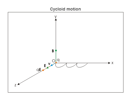
x=R sin(αBt)= z=R[1−cos(αBt)]= The motion in y-direction is due to electric force. Let the displacement in this direction be y after time t. Then: y= The position vector of the particle after time t is : r=xi+yj+zk ⇒r= Charge is placed at rest in crossed electric and magnetic fields Let electric and magnetic fields are aligned along z and x directions and charge is placed at the origin of coordinate system. Initially, there is no magnetic force as charge is at rest. However, there is electric force, which accelerates the charge in z-direction. As the particle acquires velocity in z-direction, the magnetic force comes into play and tries to rotate the particle in xz plane about a center on x-axis.
Figure 25 However, z-component of velocity keeps increasing with time due to electric force in that direction. The magnetic force though draws the charged particle away from z-axis along a curved path. This action of magnetic force is countered by electric force in z-direction. The velocity of charged particle ultimately reduces to zero at x-axis. This cycle repeats itself forming cycloid motion. The cycloid path is generated by a point on the circumference of a rolling wheel. |
INTERFERENCE
Interference in light waves occurs whenever two or more waves overlap at a given point.
TYPES OF INTERFERENCE
Interference of light waves can be either constructive interference or destructive interference.
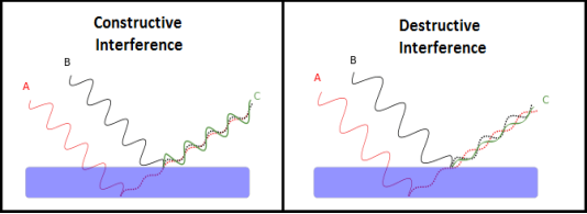
- Constructive Interference: Constructive interference takes place when the crest of one wave falls on the crest of another wave such that the amplitude is maximum. These waves will have the same displacement and are in the same phase.
- Destructive Interference: In destructive interference the crest of one wave falls on the trough of another wave such that the amplitude is minimum. The displacement and phase of these waves are not the same.
Figure 26
|
We know that the superposition of two mechanical waves can be constructive or destructive. In constructive interference, the amplitude of the resultant wave at a given position or time is greater than that of either individual wave, whereas in destructive interference, the resultant amplitude is less than that of either individual wave.
Light waves also interfere with each other. Fundamentally, all interference associated with light waves arises when the electromagnetic fields that constitute the individual waves combine.
If two light bulbs are placed side by side, no interference effects are observed because the light waves from one bulb are emitted independently of those from the other bulb. The emissions from the two light bulbs do not maintain a constant phase relationship with each other over time. Light waves from an ordinary source such as a light bulb undergo random phase changes in time intervals less than a nanosecond.
Therefore, the conditions for constructive interference, destructive interference, or some intermediate state are maintained only for such short time intervals. Because the eye cannot follow such rapid changes, no interference effects are observed. Such light sources are said to be incoherent.
CONDITIONS FOR SUSTAINED INTERFERENCE OF LIGHT
In a sustained interference pattern, the position of maximum and minimum intensity regions remains constant with time. To obtain the sustained interference, the following conditions are required:
- The sources must be coherent, that is, they must maintain a constant phase with respect to each other.
- The two light sources must emit continuous waves of the same wavelength and having the same time period.
- The distance between the two sources of light must be small. This gives large fringe width so that the fringes are separately visible.
- The sources should be monochromatic, that is, of a single wavelength.
- The two light sources must emit waves in nearly the same direction.
- Light source must be a point source.
- The distance between the two sources and screen must be large. This gives again large fringe width so that the fringes are separately visible.
THIN FILM INTERFERENCE
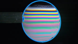
A film of thickness from 0.5 to 10 μm is a transparent medium of glass, mica, air enclosed between glass, soap film, etc. When the light is made incident on this thin film partial reflection and partial refraction occur from the top surface of the film. The refracted beam travels in the medium and again suffers partial reflection and partial refraction at the bottom surface of the film. In this way several reflected and refracted rays are produces by a single incident ray. As they moves are superimposed on each other and produces interference pattern.
Figure 27
|
DIFFRACTION
Diffraction
When the light falls on the obstacle whose size is comparable with the wavelength of light then the light bends around the obstacle and enters in the geometrical shadow. This bending of light is called diffraction.
Diffraction is the slight bending of light as it passes around the edge of an object. The amount of bending depends on the relative size of the wavelength of light to the size of the opening. If the opening is much larger than the light's wavelength, the bending will be almost unnoticeable. However, if the two are closer in size or equal, the amount of bending is considerable, and easily seen with the naked eye.
Figure 28
|
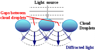
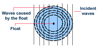
In the atmosphere, diffracted light is actually bent around atmospheric particles -- most commonly, the atmospheric particles are tiny water droplets found in clouds. Diffracted light can produce fringes of light, dark or colored bands. An optical effect that results from the diffraction of light is the silver lining sometimes found around the edges of clouds or coronas surrounding the sun or moon. The illustration above shows how light (from either the sun or the moon) is bent around small droplets in the cloud.
Optical effects resulting from diffraction are produced through the interference of light waves. To visualize this, imagine light waves as water waves. If water waves were incident upon a float residing on the water surface, the float would bounce up and down in response to the incident waves, producing waves of its own. As these waves spread outward in all directions from the float, they interact with other water waves. If the crests of two waves combine, an amplified wave is produced (constructive interference). However, if a crest of one wave and a trough of another wave combine, they cancel each other out to produce no vertical displacement (destructive interference).
Figure 29 |
This concept also applies to light waves. When sunlight (or moonlight) encounters a cloud droplet, light waves are altered and interact with one another in a similar manner as the water waves described above. If there is constructive interference, (the crests of two light waves combining), the light will appear brighter. If there is destructive interference, (the trough of one light wave meeting the crest of another), the light will either appear darker or disappear entirely.
Types of Diffraction
There are two types of diffractions
- Fresnel Diffraction: Fresnel diffraction is produced when light from a point source meets an obstacle, the waves are spherical and the pattern observed is a fringed image of the object.
- Fraunhofer Diffraction: Fraunhofer diffraction occurs with plane wave-fronts with the object effectively at infinity. The pattern is in a particular direction and is a fringed image of the source.
Figure 30 |
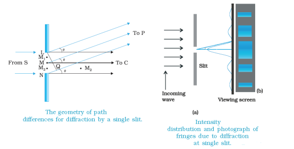
From the above figure, we observe that the source is located at a finite distance from the slit, and the screen is also at a finite distance from the slit. The source and the screen are not very far from each other. So this is a Fresnel diffraction. Here, if suppose the ray of light comes exactly at the edge of the obstacles, the path of the light is changed. So the light bends a little and meets the screen.
A beam of width α travels a distance of α2/λ , called the Fresnel distance before it starts to spread out due to diffraction. But when the source and the screen are far away from each other, and when the source is located at the infinite position, then the ray of light coming from that infinite source are parallel rays of light. So this is Fraunhofer diffraction.
Here we have to make use of the lens. But why do we use the lens? Because in Fraunhofer diffraction, the source is at infinity so the rays of light which pass through the slit are parallel rays of light.
So in order to make these rays parallel to focus on the screen, we, make use of the converging lens. The zone which we get in front of the slit is the central maxima. On either side of central maxima, there is bright zone i.e. 1st maxima.
POLARIZATION
Polarization Of Light
The phenomena of interference and diffraction confirm the wave nature of light hence neither of these phenomena is able to identify the nature of waves that light is. These phenomena do not tell whether the oscillation of light waves are longitudinal or transverse in nature. This is accomplished by the study of polarization.
A light wave that is vibrating in more than one plane is referred to as unpolarized light.
Example: Light emitted by the sun, by a lamp in the classroom, or by a candle flame is unpolarized light.
These unpolarized light is created by electric charges that vibrate in a variety of directions, this concept of unpolarized light is difficult to visualize. For simplicity it is helpful to visualize unpolarized light as a wave that has an average of half its vibrations in a horizontal plane and half of its vibrations in a vertical plane. It is possible to transform unpolarized light into polarized light.
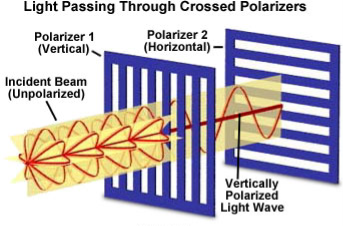
Polarized light waves are light waves in which the vibrations occur in a single plane. The process of transforming unpolarized light into polarized light is known as polarization.
Figure 31 |
Classification of light
We know that Light is a transverse electromagnetic wave, but natural light is generally unpolarized, all planes of propagation being equally probable.
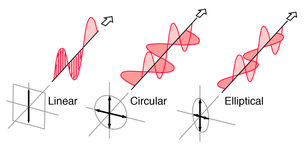
Linearly Polarized: Light in the form of a plane wave in space is said to be linearly polarized. The electric field of light is limited to a single plane along the direction of propagation.
Circularly Polarized If light is composed of two plane waves of equal amplitude by differing in phase by 90°, then the light is said to be circularly polarized. if the thumb of your right hand were pointing in the direction of propagation of the light, the electric vector would be rotating in the direction of your fingers.
Elliptically Polarized If two plane waves of differing amplitude are related in phase by 90°, or if the relative phase is other than 90° then the light is said to be elliptically polarized. If the thumb of your right hand were pointing in the direction of propagation of the light, the electric vector would be rotating in the direction of your fingers.
Figure 32: Showing Linear, Circular and Elliptical Polarization |
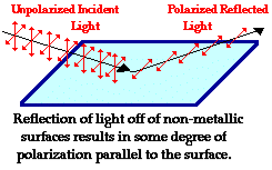
Production of Polarized Light by Reflection
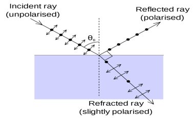
The Brewster’s law can be used to polarise the light by reflection. When unpolarised light is incident on the boundary between two transparent media, the reflected light is polarised with its electric vector perpendicular to the plane of incidence when the refracted and reflected rays make a right angle with each other.
Figure 33 |
Thus we have seen that when reflected wave is perpendicular to the refracted wave, the reflected wave is a totally polarised wave. The electric field vectors of all unpolarized light may be resolved into two components as follows;
- Tangential component- in the plane of incidence.
- Normal components – in the plane perpendicular to plane of incidence.
The angle of incidence in this case is called Brewster’s angle
Figure 34 |
If the angle of incidence θi is varied, the reflected coefficient ‘r’ for the em waves corresponding to the tangential component will vary as shown in figure. As θi increases r will decrease.
At θi = Brewster angle (about 57° for glass) r will be zero and no reflection of the tangential component will take place.
The reflected beam will contain light waves having only the normal component for the electric field as shown in figure that is the reflected light will be plane polorized with the oscillations of electric field vector normal to the plane of incidence.
Cause of Polrizaton by Reflection
The em waves are generated because of the oscillation of electric charge. The electric field vectors of the transmitted ray act on the electrons in the dielectric.
Since the intensity of em wave emitted by the oscillating charge is maximum in a direction normal to the plane of oscillation, and zero along the line of oscillations for the plane polarized light having electric field vector in the plane of incidence, there will be no emition of em waves in a direction normal to the reflected ray. In figure the direction along which no emission should occur is called as zero intensity line. Let the angle between the reflected ray and the zero intensity line be 𝛿 the angle between the reflected and tranmitted ray is π/2 + 𝛿 suppose we arrange the angle of incidence such that
n=sinθi / sinθr
n=sinθi / sin(π/2 – θi)
n=sinθi / cosθi
n=tan θi
that is possible when
θi + θr = π/2 according to Brewster’s law
from figure
θi + θr+ π/2 + = π
As θi + θr = π/2
So π/2+ π/2 + = π
= 0
The line of zero intensity and the refected ray will coincide. Thus there will be no reflection of light when the angle of incidence is equal to Brewster’s angle.
Thus the unpolarized light can be polarized by reflection as the reflected beam will contain light waves having electric field vector oscillating along normal to the plane of the incidence only.
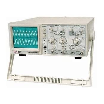
The cathode ray oscilloscope is an electronic test instrument; it is used to obtain waveforms when the different input signals are given. In the early days, it is called as an Oscillograph. The oscilloscope observes the changes in the electrical signals over time, thus the voltage and time describe a shape and it is continuously graphed beside a scale. By seeing the waveform, we can analyse some properties like amplitude, frequency, rise time, distortion, time interval and etc.
Figure 35 |
The main applications of CRO are to observe the properties of electrical and electronic signals, oscillation distortion testing, the frequency response of signals, etc. The important uses of CRO are the measurement of voltage, current, frequency, etc.
APPLICATION OF CRO
1. There are huge applications of CRO in Radio stations. It is true that our conventional CRO is not used in those radio station but they almost the same to our conventional CRO. The CROs are used in the radio station to observe the sending and receiving signal properties.
2. CRO helps to view the characteristics and property of a signal that is why it also helps to control the analog signals.
3. The shape of voltage and current waveform can be observed by CRO which helps to take the necessary decision in a radio station or communication station.
4. CRO is used for research purposes. When scientists are designed a new circuit, they check voltage, current waveforms of each part of the circuit using the Cathode Ray Oscilloscope.
5. CRO is used with the resonance circuit to observe the bandwidth, wave shape, etc.
6. CRO also used to observe the characteristics of Amplitude Modulation Circuits, Frequency Modulation Circuits, etc.
USE OF CRO (CATHODE RAY OSCILLOSCOPE)
Current Measurement: We can measure the value of current or magnitude and direction of current using CRO. By calculating the amplitude variation, horizontal and vertical cells in the CRO screen we can measure the current. We can measure both AC and DC in CRO.
Voltage Measurement: We can measure AC voltage as well as DC voltage in CRO. Here also the same procedure should be followed to measure the voltage that is calculating horizontal and vertical cells in the CRO screen.
Frequency Measurement: We not only measure voltage and current using CRO, but we can also measure the frequency of a signal by calculating the time period. Once we measure the time period of a signal then we can easily measure the frequency. The measurement of the time period using CRO also very easy.
Phase Difference Measurement: Most of the CROs have two channels. We can apply two different signals at a time on the CRO. And we can measure easily the phase difference between the two different signals. Lissajous figures in the CRO screen help us to measure the phase difference between two signals. Using this method we can also measure the frequency of two signals at a time.
