Unit 1
DC Circuit
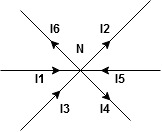
The algebraic sum of currents meeting at a junction or node in an electric circuit is zero ② or the summation of all incoming currents is always equal to the summation of all outgoing current in an electrical network. Explanation
Assuming the incoming current to be positive and outgoing current negative we have
ie
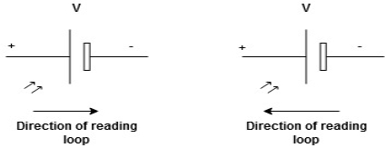
Kirchhoff’s Voltage Law (KVL) statement: the algebraic summation of all Voltage in any closed circuit or mesh of loop zero. i.e. ∑ Voltage in closed-loop = 0 the summation of the Voltage rise (voltage sources) is equal to the summation of the voltage drops around a closed loop in 0 circuits for an explanation from here determination of sigh and direction of currents (Don’t write in exams just for understanding)
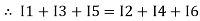
current entering a resistor is +ve and leaving should be –ve now
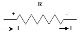
Potential Rise Potential Drop
We are reading from +V to –V we are reading from –V to +V
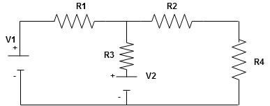
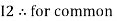
Given Circuit
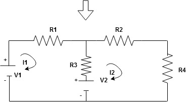
First, identify no of loops and assign the direction of current flowing in the loop Note: no of loops in-circuit = No, of unknown currents = no, of equations in the circuit
Note: keep loop direction and current direction same ie either clockwise or anticlockwise for all loops I1 I2 Now according to the direction of direction assign signs (+ve to –ve) to the resistors
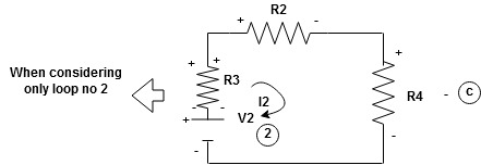
Note: voltage sources (V) polarities do not change is constant. Note: for common resistor between 2 loops appearing in the circuit like R3 give signs according to separate loops as shown
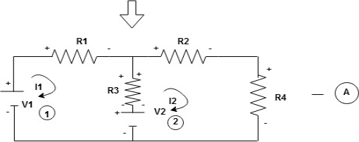
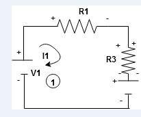
When considering only loop no 1 (+ R3 - )
- B
Now consider diagram A and write equations Two loops
Apply KVL for loop ① [B. Diagram ] (+ to drop -) = - sign and (- to rise +) = + sign
- -(
Similarly for loop no. 2 currents flowing is
Consider loop no. 1 apply KVL - - Consider loop no. 2 apply KVL - - After solving equation ① and ② we will get branch current |


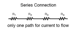
Series and parallel circuit The basic idea of a “series” connection is that components are connected end-to-end in a line to form a single path through which current can flow:
Series connection
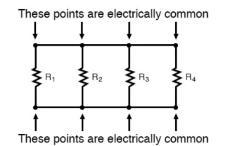
Parallel connection:
The basic idea of a “parallel” connection, on the other hand, is that all components are connected across each other’s leads. In a purely parallel circuit, there are never more than two sets of electrically common points, no matter how many components are connected. There are many paths for current flow, but only one voltage across all components:
Current and voltage division rule
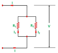
A parallel circuit acts as a current divider as the current divides in all the branches in a parallel circuit, and the voltage remains the same across them. The current division rule determines the current across the circuit impedance. The current division is explained with the help of the circuit shown below: The current I has been divided into I1 and I2 into two parallel branches with the resistance R1 and R2 and V is the voltage drop across the resistance R1 and R2.
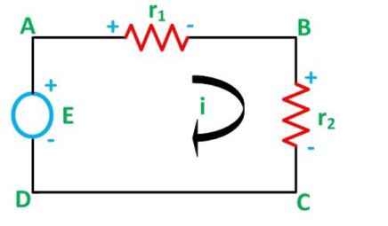
As we know, V = IR ……..(1) Then the equation of the current is written as: I1 = V/R1 and I2 = V /R2 Let the total resistance of the circuit be R and is given by the equation shown below: R = R1R2/ R1 + R2 Equation (1) can also be written as: I = V/R ……….(3) Now, putting the value of R from the equation (2) in the equation (3) we will get I = V(R1+R2)/ R1R2 ---------------------------(4) But V = I1 R1 = I2 R2 ------------------------------(5) I = I1R1(R1+R2)/ R1R2 = I1(R1+R2)/ R2---------------------(6) And now considering V = I2R2 the equation will be: I = I2R2(R1+R2)/ R1R2 = I1/R1 (R1+R2) ------------------------------(7) Thus, from the equation (6) and (7) the value of the current I1 and I2 respectively is given by the equation below: I1 + I . R2/ R1 + R2 and I2 = I . R1 / R1 + R2 Thus, in the current division rule, it is said that the current in any of the parallel branches is equal to the ratio of opposite branch resistance to the total resistance, multiplied by the total current. Voltage Division Rule The voltage division rule can be understood by considering a series circuit shown below. In a series circuit, voltage is divided, whereas the current remains the same.
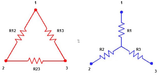
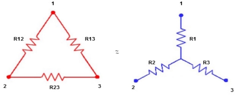
Let us consider a voltage source E with the resistance r1 and r2 connected in series across it. As we know, I = V/R or we can say I = E/R Therefore, the current (i) in the loop ABCD will be: i = E / r1 + r2 -------------------------(8) and r1 = ir1 By putting the value of I from equation (8) in equation (9) the voltage across the resistance r1 and r2 respectively are given by the equation shown below as: E1 = Er1/r1 + r2 and E2 = E r2/ r1 + r2 Thus, the voltage across a resistor in a series circuit is equal to the value of that resistor times the total impressed voltage across the series elements divided by the total resistance of the series elements. Star to delta conversion to the final equivalent resistance
We know that (from delta to star conversion) R1 =
R2 =
R1 =
Multiply ① X ② L.H.S and R.H.S
R1 R2 =
Similarly, multiply ② X ③
R2 R3 =
And ③ X①
R1 R3 =
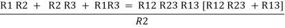
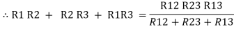
Now add equation ④, ⑤, and ⑥ L.H.S and R.H.S
(Delta) Similarly, R23 = R2+R3 +
R23 = R1+R2 +
Delta to Star Conversion to Find (Req.)
Delta = R12// (R23 + R13) =R1 + R2
=
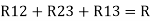
= Here let R = R12 + R23 + R13
=
Now the 3 equations after equating L.H.S. and R.H.S R1 + R2 =
R2 + R3 =
R1 + R3 =
Now subtract ② and ① on L.H.S. and R.H.S
R2+ R3 – R1 – R2 =
Now add equation ④ and ③
R3 – R1 + R1 + R3 =
2R3 =
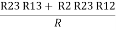
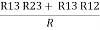
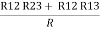
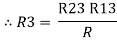
Similarly, R1 =
And R2 = R23 R12/R where R = R12 + R23 + R13 i.e. star equivalent from delta network is the ratio of the product of adjacent branches in the delta to the addition of all branches in the delta. |


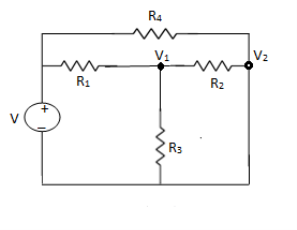
NODE ANALYSIS For these we assume every node as a voltage point and write the current equation for every element. For current source, current entering is negative.
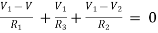
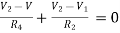
For node V1 For node V2 For V
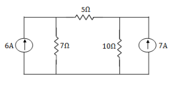
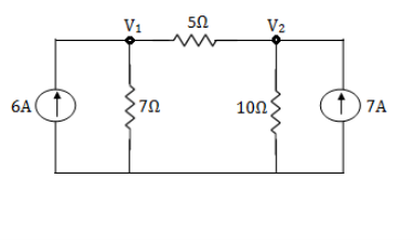
Example: Using nodal analysis find voltage across 5resistor.
Solution:
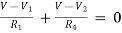
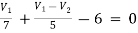
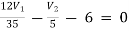
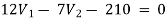
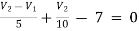
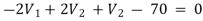
For V1 For V2
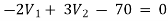
Solving 1 and 2:
For 5 voltage = = -50.9 + 57.27 = 6.37V
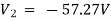
Mesh current
Mesh Current Analysis An easier method of solving the above circuit is by using Mesh Current Analysis or Loop Analysis which is also sometimes called Maxwell´s Circulating Currents method. Instead of labelling the branch currents we need to label each “closed loop” with a circulating current. Any required branch current may be found from the appropriate loop or mesh currents as before using Kirchhoff´s method. For example: : i1 = I1 , i2 = -I2 and I3 = I1 – I2 Therefore,
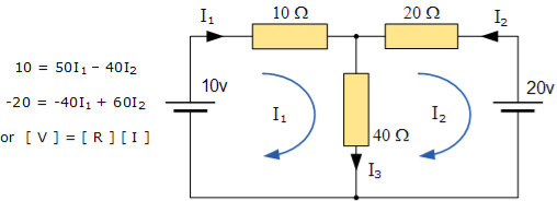
These equations can be solved quite quickly by using a single mesh impedance matrix Z. Each element ON the principal diagonal will be “positive” and is the total impedance of each mesh. Where as, each element OFF the principal diagonal will either be “zero” or “negative” and represents the circuit element connecting all the appropriate meshes. [ V] = [I] x [R] or [R] x [I] = [V]
I = V/R = R-1 x V Inverse of R = [ 60 40 40 50 ] |R| = (60 x 50 ) – (40 x 40 ) = 1400 R – 1 = 1/1400 [ 60 40 40 50] having found the inverse of R, as V/R is the same as V x R-1, we can now use it to find the two circulating currents. [I] = [ R -1] x [V] [ I1]= 1/1400 [ 60 40 [10] [I2 ] = 40 50 ] x [ -20]
I1 = (60 x 10 ) + (40 x -20 ) /1400 = -200/1400 = -0.143 A I2 = (40 x 10 ) + (50 x -20) /1400 = -600/1400 = -0.429A
Where:
and this gives I1 as -0.143 Amps and I2 as -0.429 Amps As : I3 = I1 – I2 The combined current of I3 is therefore given as : -0.143 – (-0.429) = 0.286 Amps |


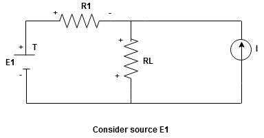
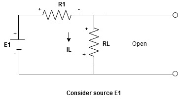
Statement: The response in any element of the linear bilateral network containing more than one source is the sum of the responses produced by the individual source acting alone. The responses mean the voltage across the element or the current in the element The voltage sources should be replaced by a short circuit and the current source must be replaced by an open circuit. Steps to apply superposition theorem : 1.
Current sources should be open
Find the current (IL1)(+) through or the voltage across the required element due to the source under consideration using a suitable n/w technique.
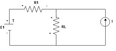
Find the current (ILII)(+) by a suitable network simplification technique
2. Add the individual current IL and ILII by the individual sources acting alone to find the total current flowing in load resistance (RL) ie |


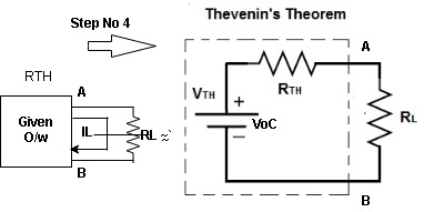
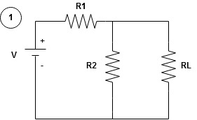
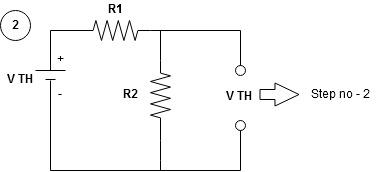
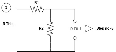
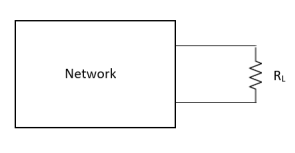
Any network containing active or passive element and or more dependent or independent voltage or current sources can be replaced by an equivalent network containing a voltage source (Thevenin's equivalent voltage VTH or VOC) and a series resistance called Thevenin's equivalent resistance
Step to apply Thevenin's theorem
|


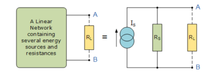
Nortons Theorem states that “Any linear circuit containing several energy sources and resistances can be replaced by a single Constant Current generator in parallel with a Single Resistor“.
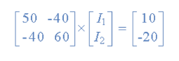
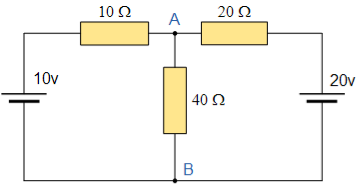
The value of this “constant current” is one which would flow if the two output terminals where shorted together while the source resistance would be measured looking back into the terminals, (the same as Thevenin). For example,.
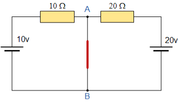
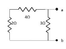
To find the Nortons equivalent of the above circuit we firstly have to remove the centre 40Ω load resistor and short out the terminals A and B to give us the following circuit.
When the terminals A and B are shorted together the two resistors are connected in parallel across their two respective voltage sources and the currents flowing through each resistor as well as the total short circuit current can now be calculated as: with A-B Shorted Out I1 = 10V/ 10 Ω = 1 amp I2 = 20V/ 20 Ω = 2 amp
Therefore I short-circuit = I1 + I2 = 2 amps.
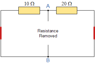
If we short-out the two voltage sources and open circuit terminals A and B, the two resistors are now effectively connected together in parallel. The value of the internal resistor Rs is found by calculating the total resistance at the terminals A and B giving us the following circuit.
Find the Equivalent Resistance (Rs)
10 Ω resistor in parallel with 20 Ω resistor RT = R1 x R2 / R1 + R2 = 20 x 10 /30 = 6.67 Ω
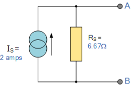
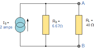
Having found both the short circuit current, Is and equivalent internal resistance, Rs this then gives us the following Nortons equivalent circuit. Nortons equivalent circuit
To solve with the original 40Ω load resistor connected across terminals A and B as shown below.
Again, the two resistors are connected in parallel across the terminals A and B which gives us a total resistance of:
RT = R1 x R2 / R1 + R2 = 6.67 x 40/ 6.67 + 40 = 5.72 Ω
The voltage across the terminals A and B with the load resistor connected is given as: Va-b = I x R = 2 x 5.72 = 11.44 V
Then the current flowing in the 40Ω load resistor can be found as:
I = V/R = 11.44/40 = 0.286 amps |
Maximum Power Transfer Theorem
where Rth is Thevenin’s equivalent resistance across a and b.
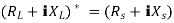
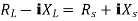
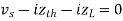
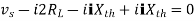
Maximum power is absorbed by ZL when Condition: Comparing real and imaginary parts OR Maximum power absorbed by ZL is
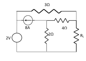
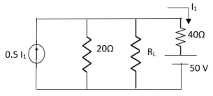
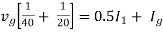
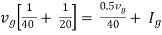
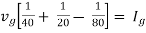
Question: Find out the value of load resistance if power absorbed is maximum.
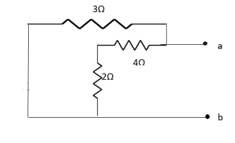
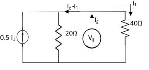
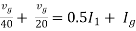
Solution: find Thevenin’s equation
Question: Find maximum power delivered is RLif its value is
Solution
Therefore, |


Reference Books:
1. V. N. Mittal, Arvind Mittal, ‘Basic Electrical Engineering’, Tata McGraw Hill publishing co. ltd, New Delhi.
2. D. P. Kothari, I.J Nagrath, ‘Basic Electrical Engineering’, Tata McGraw Hill
3. M. S. Naidu, S. Kamakshaiah, ‘Introduction to Electrical Engineering’, Tata McGraw Hill.
4. P. Tiwari, ‘Basic Electrical Engineering’, New Age Publication.
5. Vincent Del Toro, ‘Electrical Engineering Fundamentals’, Pearson
6. R. P. Jain, ‘Modern Digital Electronics’ McGraw Hill Education (India) Private Limited, Fourth Edition, 2017.
7. B. L. Theraja, ‘Applied Electronics’ S. Chand Publication
8. A.P. Malvino, ‘Electronics Principles’ TMH Publications.


