Unit 2
AC Circuit
In the field of electrical, single phase supply is the delivery of AC power by a system in which all the supply voltages change in simultaneously. This type of power supply sharing is used when the loads (home appliances) ate generally heat and lighting with some huge electric motors. When a single phase supply is connected to an AC motor doesn’t generate a rotating magnetic field, single phase motors require extra circuits for working, but such electric motors are rare over in rating of 10 kW. In every cycle, a single phase system voltage achieves a peak-value two times; the direct power is not stable.
|
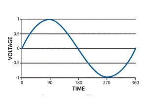
Single Phase Waveform
A load with single-phase can be power-driven from a three-phase sharing transformer in two techniques. One is with the connection between two phases or with connection among one phase and neutral. These two will give dissimilar voltages from a given power supply. This type of phase supply provides up to 230V. The applications of this supply mainly use for running the small home appliances like air conditioners, fans, heater, etc.
Single Phase Supply Benefits
The benefits of choosing a single phase supply include the following.
- The design is less complex
- Design cost is less
- Most efficient AC power supply for up to 1000 watts
- Single Phase AC Power Supply is most competent for up to 1000 watts.
- Wide-range of application uses
Single Phase Supply Applications
The applications of single-phase supply include the following.
- This power supply is applicable for homes as well as businesses.
- Used to supply plenty of power for homes, as well as nonindustrial businesses.
- This power supply is sufficient to run the motors up to about 5 horsepower (hp).
3 Basic element of AC circuit. 1] Resistance 2] Inductance 3] Capacitance Each element produces opposition to the flow of AC supply in a forward manner.
Reactance
It is opposition to the flow of an AC current offered by the inductor. XL = ω L But ω = 2 ᴫ F
It is measured in ohm
2. Capacitive Reactance (Xc) It is opposition to the flow of ac current offered by the capacitor Xc = Measured in ohm
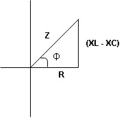
Impedance (Z) The ac circuit is to always pure R pure L and pure C it well attains the combination of these elements. “The combination of R1 XL and XC is defined and called as impedance represented as Z = R +i X Ø = 0
R = Resistance, i = denoted complex variable, X =Reactance XL or Xc
Polar Form Z = Where
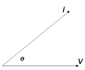
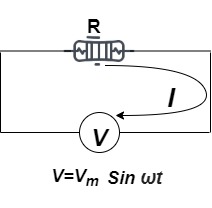
Power factor (P.F.)
It is the cosine of the angle between voltage and current
If Ɵis –ve or lagging (I lags V) then lagging P.F. If Ɵ is +ve or leading (I leads V) then leading P.F. If Ɵ is 0 or in-phase (I and V in phase) then unity P.F.
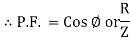
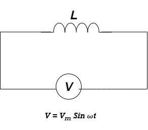
Ac circuit containing pure resisting
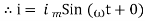
Consider Circuit Consisting pure resistance connected across the ac voltage source V = Vm Sin ωt ① According to ohm’s law i = But Im =
Phases diagram From ① and ②
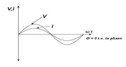
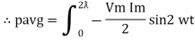
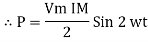
Power P = V. i Equation P = Vm sin ω t Im sin ω t P = Vm Im Sin2 ω t P =
Constant fluctuating power if we integrate it becomes zero
Average power Pavg = Pavg = Pavg = Vrms Irms
Power ware form [Resultant]
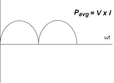
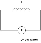
Ac circuit containing pure Inductors
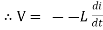
Consider pure Inductor (L) is connected across alternating voltage. Source V = Vm Sin ωt When an alternating current flow through inductance it setups alternating magnetic flux around the inductor. This changing the flux links the coil and self-induced emf is produced According to faradays Law of E M I e = at all instant applied voltage V is equal and opposite to self-induced emf [ Lenz's law] V = -e
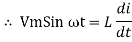
But V = Vm Sin ωt
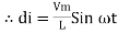
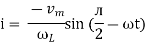
Taking integrating on both sides
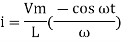
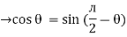
but sin (–
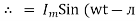
And Im=
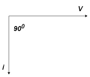
= -ve = lagging = I lag v by 900
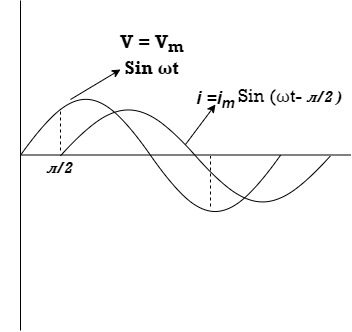
Waveform:
Phasor:
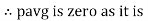
Power P = Ѵ. I = Vm sin wt Im sin (wt = Vm Im Sin wt Sin (wt –
And Sin (wt - Sin (wt –
The average value of sin curve over a complete cycle is always zero
Ac circuit containing pure capacitors:
Consider pure capacitor C is connected across an alternating voltage source Ѵ = Ѵm Sin wt Current is passing through capacitor the instantaneous charge ɡ produced on the plate of the capacitor ɡ = C Ѵ ɡ = c Vm sin wt the current is the rate of flow of charge
i = c Vm w cos wt then rearranging the above eqth. i =
i = but
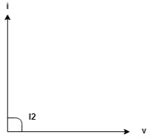
= leading = I leads V by 900
Waveform :
Phase
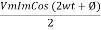
Power P= Ѵ. i = [Vm sinwt] [ Im sin (wt + X/2)] = Vm Im Sin wt Sin (wt + X/2)]
|


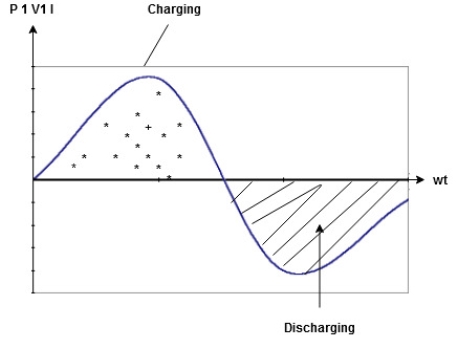
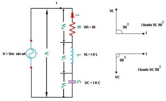
Series R-L Circuit
Consider a series R-L circuit connected across voltage source V= Vm sin wt Like some, I is the current flowing through the resistor and inductor due do this current-voltage drops across R and L R
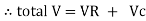
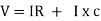
V = IR + I X L
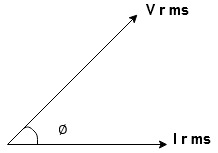
Take current as the reference phasor: 1) for resistor current is in phase with voltage 2) for Inductor voltage leads current or current lags voltage by 90 0.
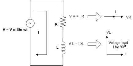
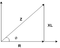
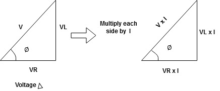
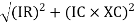
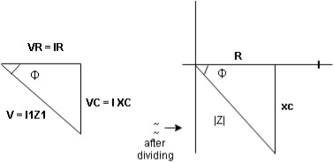
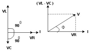
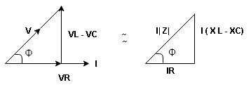
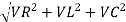
For voltage triangle Ø is the power factor angle between current and resultant voltage V and V =
V =
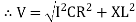
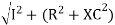
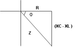
where Z = Impedance of circuit and its value is
Impedance Triangle Divide voltage triangle by I
Rectangular form of Z = R+ixL and polar from of Z = (+ j X L + Where
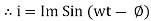
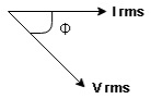
Current Equation : From the voltage triangle, we can sec. that voltage is leading current by Or i =
Resultant Phasor Diagram form Voltage and current eqth. Waveform
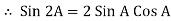
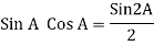
Power equation P = V .I. P = Vm Sin wt Im Sin wt – Ø P = Vm Im (Sin wt) Sin (wt – Ø) P = Since 2 sin A Sin B = Cos (A-B) – Cos (A+B) P =
①② Average Power pang = Since ② term becomes zero because Integration of cosine come from 0 to 2ƛ
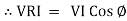
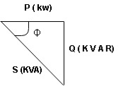
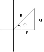
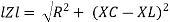
Power Triangle :
From VI = VRI + VLI B Now cos Ø in
Similarly Sin
Apparent Power Average or true Reactive or useless power Or real or active -Unit (VI) Unit (Watts) C/W (VAR) denoted by (Ø) Denoted by [S] denoted by [P]
Power
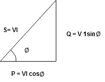
Series R-C circuit
V = Vm sin wt VR
R and C R and C And C
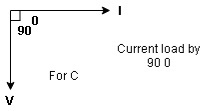
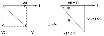
Voltage triangle: take current as the reference phasor 1) for resistor current is in phase with voltage 2) for capacitor current leads voltage or voltage lags behind current by 900
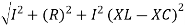
Where Ø is the power factor angle between current and voltage (resultant) V And from voltage V = V = V = V = Where Z = impedance of the circuit and its value is lZl =
Impendence triangle : Divide voltage
The rectangular form of Z = R - jXc The polar form of Z = lZl L - Ø ( - Ø and –jXc because it is in the fourth quadrant ) where lZl = and Ø = tan -1 Current equation : from voltage triangle we can see that voltage is lagging current by Ø or current is leading voltage by Ø
Or i =
Resultant phasor diagram from voltage and current equation
Resultant waveform :
Power Equation : P = V. I P = Vm sin wt. Im Sin (wt + Ø) = Vm Im sin wt sin (wt + Ø) 2 Sin A Sin B = Cos (A-B) – Cos (A+B)
Average power
pang = since 2 terms integration of cosine wave from 0 to 2ƛ become zero
Power triangle RC Circuit:
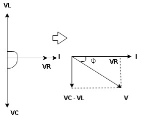
R-L-C series circuit
Consider ac voltage source V = Vm sin wt connected across the combination of R L and C. when I flowing in the circuit voltage drops across each component as shown below. VR = IR, VL = I
① XL> XC, ② XC> XL, ③ XL = XC ① XL > XC: Since we have assumed XL> XC
VL and VC are 180 0 out of phase. Therefore cancel out each other
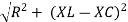
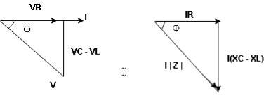
Now V = VR + VL + VC From voltage triangle V =
Impendence
Rectangular form Z = R + j (XL – XC) Polor form Z = Where And Ø = tan-1
i = i = as VL
Now V = VR + VL + VC From voltage V = V =
Polar form : Z = Where And Ø = tan-1 –
as VC since i =
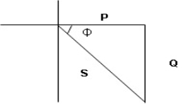
ɡȴ XL= XC then VL= VC and they are 1800 out of phase with each other Hence resultant V = VR and it will be in phase with I as shown in the below phasor diagram.
From the above resultant phasor diagram V =VR + IR Or V = I Because lZl + R Thus Impedance Z is purely resistive for XL = XC and circuit current will be in phase with source voltage.
ie pang = Vrms I rms cos Ø = 1 cos o = 1 maximum power will be transferred by the condition. XL = XC
|


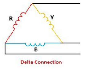
The delta connection consists three phase wires and no neutral.
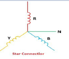
Line and Phase Values: The delta connection consists three phase wires and no neutral. Line and Phase Values: • The three components comprising a three-phase source or load are called phases. • Line voltage is the voltage measured between any two lines in a three-phase circuit. • Phase voltage is the voltage measured across a single component in a three-phase source or load. • Line current is the current through any one line between a three-phase source and load. • Phase current is the current through any one component comprising a three-phase source or load. • In balanced “Y” circuits, the line voltage is equal to phase voltage times the square root of 3, while the line current is equal to phase current. For Y circuits E line = I line = I phase • In balanced Δ circuits, the line voltage is equal to phase voltage, while the line current is equal to phase current times the square root of 3. For Δ circuits Eline = Ephase I line = • Δ-connected three-phase voltage sources give greater reliability in the event of winding failure than Y-connected sources. However, Y-connected sources can deliver the same amount of power with less line current than Δ-connected sources. Solution of balanced three phase circuits : The following steps are given below to solve the balanced three-phase circuits. Step 1 – First of all draw the circuit diagram. Step 2 – Determine XLP = XL/phase = 2πfL. Step 3 – Determine XCP = XC/phase = 1/2πfC. Step 4 – Determine XP = X/ phase = XL – XC Step 5 – Determine ZP = Z/phase = √R2P + X2P Step 6 – Determine cosϕ = RP/ZP; the power factor is lagging when XLP > XCP and it is leading when XCP > XLP. Step 7 – Determine the V phase. For star connection VP = VL/√3 and for delta connection VP = VL Step 8 – Determine IP = VP/ZP. Step 9 – Now, determine the line current IL. For star connection IL = IP and for delta connection IL = √3 IP Step 10 – Determine the Active, Reactive and Apparent power.
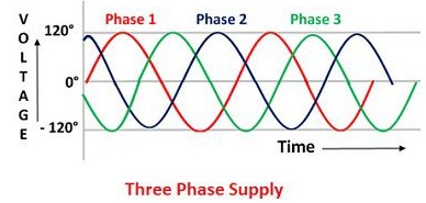
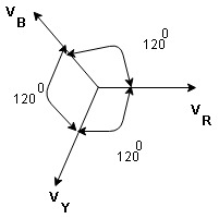
Equation VR = Vm Sin wt VY = Vm Sin (wt-1200) VB = sin (wt – 2400) Or VB = Vm sin (wt + 1200)
ɡȴ same amount of power is to transmitted than the cross-sectional area of conductor used for 3 Ø system is small as compared to that for single Ø system.
3Ø system in which 3 voltages are of identical magnitude and frequency and are displaced by 1200 from each other called as Symmetrical system. |


1. V. N. Mittal, Arvind Mittal, ‘Basic Electrical Engineering’, Tata McGraw Hill publishing co. ltd, New Delhi.
2. D. P. Kothari, I.J Nagrath, ‘Basic Electrical Engineering’, Tata McGraw Hill
3. M. S. Naidu, S. Kamakshaiah, ‘Introduction to Electrical Engineering’, Tata McGraw Hill.
4. P. Tiwari, ‘Basic Electrical Engineering’, New Age Publication.
5. Vincent Del Toro, ‘Electrical Engineering Fundamentals’, Pearson
6. R. P. Jain, ‘Modern Digital Electronics’ McGraw Hill Education (India) Private Limited, Fourth Edition, 2017.
7. B. L. Theraja, ‘Applied Electronics’ S. Chand Publication
8. A.P. Malvino, ‘Electronics Principles’ TMH Publications.


