UNIT 2
ACOUSTICS AND INTRODUCTION TO MECHANICS
ARCHITECTURAL ACOUSTICS
Acoustics, the science concerned with the production, control, transmission, reception, and effects of sound. The term is derived from the Greek akoustos, meaning heard.
Acoustics in architecture means improving sound in environments. Although it is a complex science, understanding the basics - and making efficient and effective decisions - is much easier than you might think. The first step is to understand that there are two technical categories used in acoustics: soundproofing and acoustical treatment. Soundproofing means "less noise" and acoustical treatment, "better sound”.
According to classic acoustics theory there are five requirements which, when met, result in good acoustics:
- An appropriate reverberation time
- Uniform sound distribution
- An appropriate sound level
- An appropriately low background noise
- No echo or flutter echo
Acoustic requirement for good auditorium is as follows-
- The initial sound should be of adequate intensity.
- The sound should be evenly distributed throughout the hall.
- The successive nodes should be clear & distinct.
- Noise has to be taken care of.
- The size & the shape of the ball have also to be taken care.
These requirements can be achieved by following ways-
Site/location:-Before construction the first important factor to be considered is the location. For best acoustical quality of the hall, it should be far from railway tracks, industrial areas, airports, & highways, etc.
Size: - The size of the hall should be optimum, neither big nor small. It is small uneven distribution of sound will take place due to the formations of stationary waves. If size is too big reverberation time will be more that results in confusion & unpleasant sound.
Shape: - Instead of parallel walls spade walls are preferred, curved surfaces should be built with proper care.
Reverberation: - Reverberation time (T) should be neither too small nor too large. If it is small intensity will be weak. If large sound will be unpleasant. Thick carpets curtains, upholstered chairs, audience take care of reverberation. For lecture halls the reverberation time is approximately 0.5sec, for music concerts hall-1.5sec, for cinema theatres-2sec
Absorption: - Use of proper absorbent material enhances the quality of sound.
Echelon effect: - The regular intervals/space between staircase or railings give repeated echo, this makes the sound unpleasant, so thick carpets take care of this & wide gaps between staircases are generally preferred. No echo or flutter echoes must occur for the acoustics to be good. It is easy to prevent echo by installing a little sound-absorbing material on the wall.
ABSORPTION COEFFICIENT
The coefficient of absorption of material is defined as the ratio of the sound energy absorbed by the surface to that of the total incident sound energy on the surface.
Absorption Coefficient = |
As all sound waves falling on an open window pass through, it can be assumed that an open window behaves as perfect absorber of sound and hence the standard of absorption is taken as the unit area of an open window as a standard unit of absorption.
Thus, the absorption coefficient of a material is defined as the rate of the sound energy absorbed by a certain area of the surface to that of open window of same area.
The absorption coefficient of a surface is defined as the reciprocal of its area which absorbs the same sound energy absorbed at a unit area of an open window.
REVERBERATION
Reverberation and Time of Reverberation
When a sound is produced in a building, it lasts too long after its production. It reaches to the listener a number of times. Once it reaches directly from the source and subsequently after reflection from the walls, windows, ceiling and flour of hall. The listener therefore receives series of sounds of diminishing intensity. By reverberation is meant the prolonged reflection of sound from the walls, floor and ceiling of a room.
The reverberation is defined as the persistence of audible sound after the source has stopped to emit sound. The duration for which the sound is stopped is called reverberation time. This time is measured from the instant the source stops emitting sound.
The time of reverberation is defined as the time taken by the sound to fall below the minimum audibility measured from the instant when the source stopped emitting sound.
According to Prof. W. C. Sabine, the standard reverberation time is defined as the time taken by sound to fall to one millionth of its intensity just before the sound is cut off.
SABINE's FORMULA FOR REVERBERATION TIME
According to W. C. Sabine, the time of reverberation depends up on
1. Size of hall,
2. Loudness of the sound,
3. Kind of music or sound for which hall is to be used.
Acoustics and Ultrasonic Reverberation Time
T = 0.165 V/
T = 0.165 V/ A
Where V-Volume of hall in m3
a - Absorption coefficient
S - Area of reflecting surface in a square meter
 Absorption of hall.
FACTORS AFFECTING ACOUSTICS OF BUILDINGS AND THEIR REMEDIES
Acoustically good hall we mean that in which every syllable or musical note reaches an audible level of loudness at every point of the hall and then quickly dies away to make room ready for the next syllable or group of notes. Following are the factors affecting architectural acoustics.
- REVERBERATION
In a hall, if the reverberation is large there is of successive sounds which result in loss of clarity in hearing. However if the reverberation is very small, the loudness is inadequate Thus the time of reverberation for a hall should neither too large nor too small. The preferred value of the time of reverberation is called optimum the reverberation time. According to W. C. Sabine standard reverberation time is given by:
T = 0.165 V/
T = 0.165 V/ A
Where V-Volume of hall in m3
a - Absorption coefficient
S - Area of reflecting surface in a square meter
 Absorption of hall
The reverberation can be controlled by the following factors:
- By providing windows and ventilators which can be opened and closed to make the optimum time of reverberation
- Decorating the walls by pictures and maps
- Using heavy curtains with folds
- The walls are lined with absorbent material such as felt, fibreboard, glass wool etc.
- Having full capacity of audience
- By covering floor with carpet
- By providing acoustics tiles
2. ADEQUATE LOUDNESS
With large absorption the time of reverberation will be smaller which will minimize the chances of confusion and may go below the level of intelligibility of hearing. Hence sufficient loudness in every portion of the hall is an important factor for satisfactory hearing.
The loudness can he maintained at desired level by:
Using large sounding boards behind the speaker and facing the audience.
Large polished wooden reflecting surfaces immediately above the speakers.
Low ceiling are also useful in reflecting the sound energy towards the audience.
By providing additional sound energy using more number of speakers
3. FOCUSING DUE TO WALLS AND CEILINGS
If there are focusing surfaces like concave, spherical, cylindrical or parabolic etc. on the walls or ceiling or the floor of the hall, they produce concentration of the sound in to particular region, while in some other parts no sound reaches at all. Thus there will be non- uniformity in the distribution of sound energy in the hall.
For uniform distribution of sound in the hall:
- There should be no curved surfaces. If such surfaces are present, they should be covered with absorbent material.
- Ceiling should be low.
- Arrange speaker at the focus of parabolic reflecting surface. This will helpful to reflect beam of sound in the hall.
4. ECHOES
An echo is heard, when direct and reflected sound waves coming from the same source reach the listener with time interval of about  th second. It should be avoided as far as possible by absorption.
Echoes can he avoided by:
- Covering long distant walls with curtain or absorbent material
- Covering high ceiling with absorbent material
5. ECHELON EFFECT
A set of railings, pillars or any regular spacing of reflected surfaces may produce a musical note due to regular succession of the echoes of the original sound to the listener. This makes the original sound confused.
This can be avoided by:
- Covering steps with carpet
- Covering flour with carpet
- Avoid pillars in the hall
6. BALCONIES
There are chances of reflection of sound from the railing of balcony. This may lead to the problem like echelon effect or echoes.
This can be eliminated by:
- Adjust height to depth ratio as 2: 1
- Use grills and bars for railings instead of bricks
7. SEATING ARRANGEMENT
This is one of the factors to be taken care at the time of arranging the seats.
It preferred to arrange:
- Seats perpendicular to the direction of sound for better audibility
- Seats must be gradually elevated to take care of absorption of sound energy by human body.
8. EXTRANEOUS NOISE AND SOUND INSULATION
In a good hall no noise should reach from outside. Noise may be defined as unwanted sound such as:
Outside Noise: street traffic, hammering, drilling, operating machinery, moving of furniture, electrical generator etc.
Inside Noise: machinery, typewriters, telephone, mobiles, projector etc.
This extraneous noise can be avoided by:
- Avoiding openings for pipes and ventilators
- Allotting suitable locations for doors and windows
- Using heavy glasses to doors and windows
- By providing double wall construction with air space between them
- By interposing layers of some acoustical insulators
- Use of soft floor finish e.g. carpet, rubber etc.
- Insulating machines like refrigerators, lifts, typewriters, projector etc.
- Constructing small sound proof cabin for machine and office staff
- Making hall sound proof
9. FREEDOM FROM RESONANCE
If the frequency of the created sound is equal to original sound, then the original music will be reinforced. Due to the interference between original sounds is distorted. Enclosed air in the hall also causes resonance.
This can be avoided by:
- Using absorbing material on reflecting surfaces
- Providing decoration which include holes in the design on interior wall
- Using ventilators whenever necessary
ULTRASONIC
Ultra (meaning beyond) + sonic (meaning sound) = beyond the audible sound range i.e. 20kHZ
As we know Sound wave is a vibration that can be transmitted through a medium like air, water, and metals. Whereas Ultrasonic wave is defined as inaudible sound with high frequency of range more than 20 kHz which is actually higher than the upper audible limit of human hearing.A healthy body can hear soundwave of frequency approximately 20 kilohertz. Also this range can vary from human to human.
In other words Sound wave which is not intended to be heard by human is also called ultrasonic wave.
Generally these waves are called as high frequency waves
PROPERTIES
- The ultrasonic waves cannot travel through vacuum.
- These waves travel with speed same as sound wave travel in any given medium.
- In homogeneous medium the velocity of ultrasonic wave is constant.
- These waves can also weld some material like plastics and metals.
- They have high energy content.
- Ultrasonic waves get reflected, refracted and absorbed just like sound waves.
- They can be transmitted over large distances without any appreciable loss of energy.
- They produce intense heating effect when passed through a substance.
- The ultrasonic waves have high frequency.
- Because of their smaller wavelength Ultrasonic waves produce negligible diffraction effects.
- Ultrasonic waves can produce vibrations in low viscosity liquids.
- When the ultrasonic wave is absorbed by a medium, it produces heat because of high frequency and high energy and that energy is used to drill and cut thin metals.
Potential energy is energy which results from position or configuration. The SI unit for energy is the joule = newton x meter in accordance with the basic definition of energy as the capacity for doing work.
An object may have the capacity for doing work as a result of its position in a gravitational field (gravitational potential energy), an electric field (electric potential energy), or a magnetic field (magnetic potential energy). It may have elastic potential energy as a result of a stretched spring or other elastic deformation.
If force acting on an object is a function of position only, it is said to be a conservative force, and it can be represented by a potential energy function which for a one-dimensional case satisfies the derivative condition
 = F(x) ………….(1)
The integral form of this relationship is
V(x) =  ………….(2)
which can be taken as a definition of potential energy
Note that there is an arbitrary constant of integration in that definition, showing that any constant can be added to the potential energy. Practically, this means that you can set the zero of potential energy at any point which is convenient.
The potential energy V is equal to the work you must do to move an object from the V=0 reference point to the position r. The reference point at which you assign the value V=0 is arbitrary, so may be chosen for convenience, like choosing the origin of a coordinate system.
The force on an object is the negative of the derivative of the potential function V. This means it is the negative of the slope of the potential energy curve. Plots of potential functions are valuable aids to visualizing the change of the force in a given region of space.
If the potential energy function V is known, the force at any point can be obtained by taking the derivative of the potential.
F in the definition of potential energy is the force exerted by the force field, e.g., gravity, spring force, etc. The potential energy V is equal to the work you must do against that force to move an object from the V=0 reference point to the position r. The force you must exert to move it must be equal but oppositely directed, and that is the source of the negative sign. The force exerted by the force field always tends toward lower energy and will act to reduce the potential energy.
The negative sign on the derivative shows that if the potential V increases with increasing r, the force will tend to move it toward smaller r to decrease the potential energy.
For Example
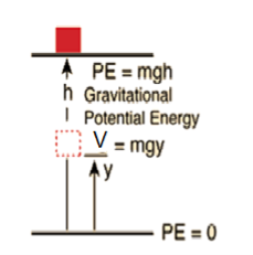
(i) Gravitational Potential energy V at a height h is given as mgh.
Fy = 
Fy = 
Fy = 
1 Figure
|
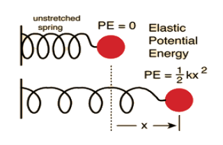
(ii) Spring-Mass System
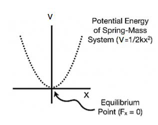
We know that Elastic potential energy of unstreched spring V is zero and Elastic potential energy of streched spring V is given by  Here, the potential energy is quadratic (bowl-shaped) function. The force is zero at x=0. At that point, the slope of the potential energy graph is also zero. This point is stable because it is at the bottom of the “bowl-shaped” potential energy. Also, the force to the right side of the equilibrium point is pointing to the left (F=−kx<0 because x>0) and the force to the left side of the equilibrium point is pointing to the right (F=−kx>0 because x<0).
Fx = 
Fx = 
Fx =  kx
kx
2 Figure
|
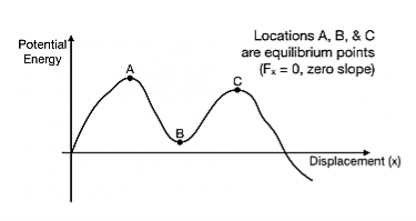
In a more general potential energy diagram (to the right), you can determine the equilibrium points by finding where the slope is zero (Fx=0). The stability of those points can be classified as stable or unstable.
3 Figure
|
A way to think about stability is to think of a bead sitting at the equilibrium location. Is it stable against small pushes? For example, at location B, a small push on the bead would cause the bead to move up a bit, but it would come back – location B is stable. At location A and C, a bead given a small push would run away from those locations – both are unstable.
4 Figure
|
Similarly we can obtain potential energy if the value of force is known, by integrating force as given in equation (2).
To find the force in three-dimensions, this derivative of the potential becomes the gradient of the potential,
 =−
=− V=⟨
V=⟨

 ⟩
⟩
 = =
= =


The triangle vector is called the gradient operator, or "del," and can be written like this:


is called a vector operator, because it has components like a vector and its partial derivatives operate on a quantity placed to its right. When operating on a scalar function such as potential energy, it is also called the gradient operator. To simplify the notation, we write
 ≡
≡ 


Note that  → is not itself a vector – it has to "act upon" a function to create a vector. When it performs this function, the derivatives define vector components which are conveniently multiplied by the unit vectors.
Where ∇ is called “del” or sometimes “nabla” (after an ancient Hebrewharp of similar shape).With this notation, the relation between force and potential energy can be written
F=−∇V
When ∇ operates on a scalar to give a vector, the combination ∇U is called the gradient of U, sometimes written grad U.
On spherical coordinates, the gradient of a general function V is:
 V =
V =  er +
er + 
 eθ +
eθ + eϕ
eϕ
If V(r,θ,ϕ) only depends on r, that is V=V(r), which is exactly the case of the gravitational potential, then the partial derivatives with respect to θ and ϕ are zero, and therefore the ∇ resumes to:
 V =
V =  er
er
EQUIPOTENTIAL SURFACE
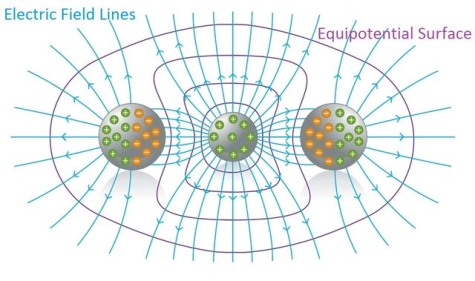
We already studied about Electric field lines help us to understand electric fields, because they give us a "visual" representation of an Electric field. Each of those lines represents the "direction" of the electric field, because the electric field (vector) is tangent to each point of those lines.
In a similar way, the potential at points inside of an electric field can be represented "graphically" using equipotential surfaces.
An Equipotential surface is a surface where the potential is the same (equal) for any point on top of that surface.
In an area where an electric field exists we can construct an equipotential surface that passes through any point. In the diagrams we only show some equipotential lines, mostly with the same potential difference between neighbouring surfaces. And lasty, no point can have two or more different potentials and so equipotential lines can never be tangent and can never intersect.
5 Figure
|
NEED OF EQUIPOTENTIAL SURFACES
When moving "along" an equipotential surface the potential is the same for any point where a test charge passes by. Which means that the electric field E doesn't produce Work to the test charge on top of an equipotential surface. More specifically the electric field E can't have a vector component tangent to that surface, so that this component can produce Work to the motion of the moving charge on top of the surface.
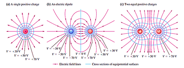
So, the electric field is vertically across to any point of the equipotential surface and to the equipotential surface as a whole. Something which gets us to the conclusion that Electric field lines and Equipotential surfaces are always vertically across to each other.
Generally, electric field lines are curved lines and equipotential surfaces are curved surfaces. In the special case of a uniform field where the electric field lines are parallel to each other, the equipotential surfaces are parallel surfaces vertically across to the electric field's lines.
|
6 Figure: Cross Sections of equipotential surfaces (blue lines) and electric field lines (red lines) for assemblies of point charges. There are equal potentials differences between adjacent surfaces.
When the charges inside of a conductor are not moving (are at "rest") then the electric field directly outside of the conductor must be vertically across to every point on top of it's surface.
Of course the electric field E = 0 in every point inside of the conductor (electrostatics), cause else the charges would be moving. This means that the component of E that is tangent to the surface, inside of the conductor, is zero at every point. Therefore the tangent component of E directly outside of the conductor is also zero. If that was not true then we would violate the laws of electrostatics. And so, the electric field is vertically across to every point of the conductor's surface. As a result, a conductive surface is always an equipotential surface.
When the charges inside of a conductor are not moving (are at "rest") then the electric field directly outside of the conductor must be vertically across to every point on top of it's surface.
Of course the electric field E = 0 in every point inside of the conductor (electrostatics), cause else the charges would be moving. This means that the component of E that is tangent to the surface, inside of the conductor, is zero at every point. Therefore the tangent component of E directly outside of the conductor is also zero. If that was not true then we would violate the laws of electrostatics. And so, the electric field is vertically across to every point of the conductor's surface. As a result an conductive surface is always an equipotential surface.
So we concluded that any surface over which the potential is constant is called an equipotential surface. In other words, the potential difference between any two points on an equipotential surface is zero. No work is required to move a charge from one point to another on the equipotential surface. In other words, any surface with the same electric potential at every point is termed as an equipotential surface.
Equipotential Points: If the points in an electric field are all at the same electric potential, then they are known as the equipotential points. If these points are connected by a line or a curve, it is known as an equipotential line. If such points lie on a surface, it is called an equipotential surface. Further, if these points are distributed throughout a space or a volume, it is known as an equipotential volume.
WORK DONE IN EQUIPOTENTIAL SURFACE
The work done in moving a charge between two points in an equipotential surface is zero. If a point charge is moved from point VA to VB, in an equipotential surface, then the work done in moving the charge is given by
W = q0(VA –VB)
As VA – VB is equal to zero, the total work done is W = 0.
Some important properties of equipotential surfaces:
- Work done in moving a charge over an equipotential surface is zero.
- The electric field is always perpendicular to an equipotential surface.
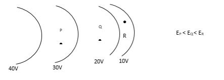
- The spacing between equipotential surfaces enables us to identify regions of strong and weak fields.
- Two equipotential surfaces can never intersect. If two equipotential surfaces could intersect, then at the point of intersection there would be two values of electric potential which is not possible.
- For a point charge, the equipotential surfaces are concentric spherical shells.
- For a uniform electric field, the equipotential surfaces are planes normal to the x-axis
- The direction of the equipotential surface is from high potential to low potential.
- Inside a hollow charged spherical conductor the potential is constant. This can be treated as equipotential volume. No work is required to move a charge from the centre to the surface.
- For an isolated point charge, the equipotential surface is a sphere. i.e. concentric spheres around the point charge are different equipotential surfaces.
- In a uniform electric field, any plane normal to the field direction is an equipotential surface.
- The spacing between equipotential surfaces enables us to identify regions of a strong and weak field i.e. E= −dV/dr ⇒ E ∝ 1/dr
12. 7 Figure
|
GRADIENT
The gradient is a fancy word for derivative, or the rate of change of a function. It’s a vector (a direction to move) that
- Points in the direction of greatest increase of a function
- Is zero at a local maximum or local minimum (because there is no single direction of increase)
The term "gradient" is typically used for functions with several inputs and a single output (a scalar field). Yes, you can say a line has a gradient (its slope), but using "gradient" for single-variable functions is unnecessarily confusing. Keep it simple.
“Gradient” can refer to gradual changes of colour, but we’ll stick to the math definition. You’ll see the meanings are related.
PROPERTIES OF THE GRADIENT
Now that we know the gradient is the derivative of a multi-variable function, let’s derive some properties.
The regular, plain-old derivative gives us the rate of change of a single variable, usually x. For example, dF/dx tells us how much the function F changes for a change in x. But if a function takes multiple variables, such as x and y, it will have multiple derivatives: the value of the function will change when we “wiggle” x (dF/dx) and when we wiggle y (dF/dy).
We can represent these multiple rates of change in a vector, with one component for each derivative. Thus, a function that takes 3 variables will have a gradient with 3 components:
- F(x) has one variable and a single derivative: dF/dx
- F(x,y,z) has three variables and three derivatives: (dF/dx, dF/dy, dF/dz)
The gradient of a multi-variable function has a component for each direction.
And just like the regular derivative, the gradient points in the direction of greatest increase.
However, now that we have multiple directions to consider (x, y and z), the direction of greatest increase is no longer simply “forward” or “backward” along the x-axis, like it is with functions of a single variable.
If we have two variables, then our 2-component gradient can specify any direction on a plane. Likewise, with 3 variables, the gradient can specify and direction in 3D space to move to increase our function.
Gradient tells you how much something changes as you move from one point to another (such as the pressure in a stream). The gradient is the multidimensional rate of change of a particular function. The gradient vector is a representative of such vectors which present the value of differentiation in all the 360° direction for the given point on the curve”
The gradient is a vector function which operates on a scalar function to produce a vector whose scale is the maximum rate of change of the function at the point of the gradient and which is pointed in the direction of that utmost rate of change. The symbol for the gradient is ∇.
8 Figure
|
(i) A gradient of a scalar quantity is a Vector quantity.
(ii) The magnitude of that vector quantity is equal to the Maximum rate of change of that scalar quantity.
(iii) Change of scalar quantity does not depend only on the coordinate of the point, but also on the direction along which the change is shown.
For the gradient of a vector field, you can think of it as the gradient of each component of that vector field individually, each of which is a scalar. The gradient always points in the direction of the maximum rate of change in a field.
PHYSICAL SIGNIFICANCE OF GRADIENT
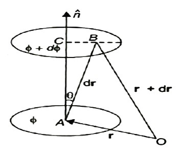
A scalar field may be represented by a series of level surfaces each having a stable value of scalar point function θ. The θ changes by a stable value as we move from one surface to another. These surfaces are known as Gaussian surfaces. Now let the two such surfaces are very close together, be represented by two scalar point functions and (θ + d θ). Let ‘r’ and (r + d θ) be the position vectors of points A and B, on the surfaces θ and (θ + d θ) correspondingly with respect to an origin 0 as shown in Figure. Clearly, the vector AB will be dr. Let the least detachment between the two surfaces ‘dn’ be in the direction of unit usual vector n at A.
9 Figure dn = dr cos θ = | n | dr | cos θ =n .dr Dϕ = ∂ϕ/ dn =∂ϕ/dn n .dr…… (1) Since the continuous scalar function defining the level surfaces (Gaussian surfaces) has a value θ at point A (x, y, z) and (θ + dθ) at point (x + dx, y + dy, z + dz), we have dϕ = ∂ ϕ/dx dx +dϕ/∂y + ∂ϕ/∂x dz = (I ∂ϕ/∂x +j ∂ϕ/vy +k ∂ϕ/∂z) .(idx +jdy +kdz) = ∆ ϕ. dr … … (2) From equations (1) and (2), equating the values of d θ, We obtain ∆θ .dr =∆ ϕ= ∂ϕ/ ∂n n .dr As dr is an arbitrary vector, we have ∆ϕ =∂ϕ/∂ n Grad ϕ = ∂ ϕ/∂n n
|
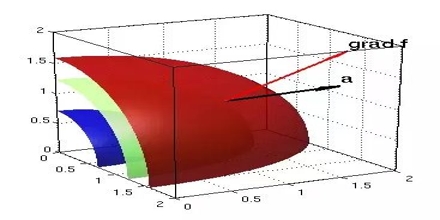
Therefore, the gradient an of a scalar field at any point is a vector field, the scale of which is equal to the highest rate of increase of θ at that point and the direction of it is similar as that of usual to the level surface at that point.
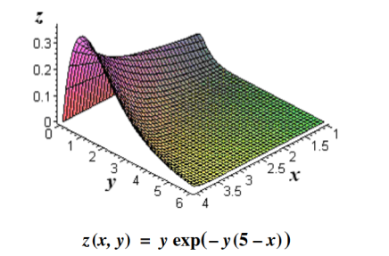
Its physical significance of grad can be understand in terms of the graph of some function z = f(x, y), where f is a reasonable function – say with continuous first partial derivatives. In this case we can think of the graph as a surface whose points have variable heights over the xy – plane. An illustration is given below.
10 Figure
|
If, say, we place a marble at some point (x, y) on this graph with zero initial force, its motion will trace out a path on the surface, and in fact it will choose the direction of steepest descent. This direction of steepest descent is given by the negative of the gradient of f. One takes the negative direction because the height is decreasing rather than increasing.
Using the language of vector fields, we may restate this as follows: For the given function f(x, y), gravitational force defines a vector field F over the corresponding surface z = f(x, y), and the initial velocity of an object at a point (x, y) is given mathematically by –∇f(x, y). The gradient also describes directions of maximum change in other contexts. For example, if we think off as describing the temperature at a point(x, y), then the gradient gives the direction in which the temperature is increasing most rapidly.
A conservative force may be defined as one for which the work done in moving between two points A and B is independent of the path taken between the two points. The implication of "conservative" in this context is that you could move it from A to B by one path and return to A by another path with no net loss of energy - any closed return path to A takes net zero work.
A further implication is that the energy of an object which is subject only to that conservative force is dependent upon its position and not upon the path by which it reached that position. This makes it possible to define a potential energy function which depends upon position only.
A conservative force is a force that does zero work done in a closed path. If only these forces act then the mechanical energy of the system remains conserved. Examples of conservative force: Gravitational force, spring force etc.
On the other hand, non-conservative forces are those forces which cause loss of mechanical energy from the system. In the above case friction is the non-conservative force. But as we know energy can neither be created nor destroyed hence these forces convert mechanical energy into heat, sound, light etc.
Now, Conservative force has one more property that works done by it is independent of the path taken.
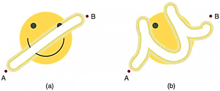
Forces are either conservative or non-conservative. Conservative forces we already discussed. A non-conservative force is one for which work depends on the path taken. Friction is a good example of a non-conservative force. As illustrated in Figure 11,
11 Figure
|
Work done against friction depends on the length of the path between the starting and ending points. Because of this dependence on path, there is no potential energy associated with non-conservative forces. An important characteristic is that the work done by a non-conservative force adds or removes mechanical energy from a system. Friction, for example, creates thermal energy that dissipates, removing energy from the system. Furthermore, even if the thermal energy is retained or captured, it cannot be fully converted back to work, so it is lost or not recoverable in that sense as well.
In Figure 11. The amount of the happy face erased depends on the path taken by the eraser between points A and B, as does the work done against friction. Less work is done and less of the face is erased for the path in (a) than for the path in (b). The force here is friction, and most of the work goes into thermal energy that subsequently leaves the system (the happy face plus the eraser). The energy expended cannot be fully recovered.
How Non-conservative Forces Affect Mechanical Energy
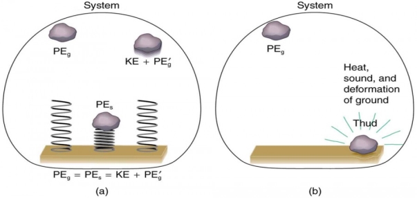
Mechanical energy may not be conserved when non-conservative forces act. For example, when a car is brought to a stop by friction on level ground, it loses kinetic energy, which is dissipated as thermal energy, reducing its mechanical energy. Figure 12 compares the effects of conservative and non-conservative forces. We often choose to understand simpler systems such as that described in Figure 2a first before studying more complicated systems as in Figure 2b.
12 Figure
|
12 Figure: Comparison of the effects of conservative and non-conservative forces on the mechanical energy of a system.
In the above figure (a), A system with only conservative forces. When a rock is dropped onto a spring, its mechanical energy remains constant (neglecting air resistance) because the force in the spring is conservative. The spring can propel the rock back to its original height, where it once again has only potential energy due to gravity.
Whereas (b) A system with non-conservative forces. When the same rock is dropped onto the ground, it is stopped by non-conservative forces that dissipate its mechanical energy as thermal energy, sound, and surface distortion. The rock has lost mechanical energy.
Applying Energy Conservation with Non-conservative Forces
When no change in potential energy occurs, applying KEi + PEi + Wnc = KEf + PEf amounts to applying the work-energy theorem by setting the change in kinetic energy to be equal to the net work done on the system, which in the most general case includes both conservative and non-conservative forces. But when seeking instead to find a change in total mechanical energy in situations that involve changes in both potential and kinetic energy, the previous equation KE i + PEi + Wnc = KEf + PEf says that you can start by finding the change in mechanical energy that would have resulted from just the conservative forces, including the potential energy changes, and add to it the work done, with the proper sign, by any non-conservative forces involved.
Let us understand the concept of forces by some examples
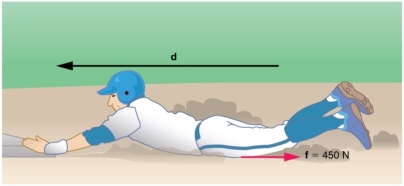
Example1 Calculating Distance Travelled: How Far a Baseball Player Slides
Consider the situation shown in Figure 13, where a baseball player slides to a stop on level ground. Using energy considerations, calculate the distance the 65.0-kg baseball player slides, given that his initial speed is 6.00 m/s and the force of friction against him is a constant 450 N.
|
Figure 13: The baseball player slides to a stop in a distance d. In the process, friction removes the player’s kinetic energy by doing an amount of work equal to the initial kinetic energy.
Solution:
Friction stops the player by converting his kinetic energy into other forms, including thermal energy. the work done by friction, which is negative, is added to the initial kinetic energy to reduce it to zero. The work done by friction is negative, because f is in the opposite direction of the motion (that is, θ = 180º, and so cos θ = −1). Thus Wnc = −fd. The equation simplifies to
 mvi2−fd=0
or
fd=  mvi2
mvi2
Solving the previous equation for d and substituting known values yields
d=  ==
== 
d = =2.60 m
The most important point of this example is that the amount of non-conservative work equals the change in mechanical energy. For example, you must work harder to stop a truck, with its large mechanical energy, than to stop a mosquito.
Example 2: Calculating Distance Travelled: Sliding Up an Incline
Suppose that the player from Example 1 is running up a hill having a 5.00º incline upward with a surface similar to that in the baseball stadium. The player slides with the same initial speed. Determine how far he slides.
|
Figure 14: The same baseball player slides to a stop on a 5.00º slope.
Solution
In this case, the work done by the non-conservative friction force on the player reduces the mechanical energy he has from his kinetic energy at zero height, to the final mechanical energy he has by moving through distance d to reach height h along the hill, with h = d sin 5.00º.
This is expressed by the equation KE + PEi + Wnc = KE f + PEf.
The work done by friction is again Wnc = −fd;
Initially the potential energy is PEi = mg · 0 = 0
and the kinetic energy is KEi= mvi2
mvi2
; the final energy contributions are KEf = 0 for the kinetic energy
and PEf = mgh = mgd sin θ for the potential energy.
Substituting these values gives
 mvi2 +0+(−fd)=0+mgdsinθ
Solve this for d to obtain
d = 
d = =2.31 m
As might have been expected, the player slides a shorter distance by sliding uphill. Note that the problem could also have been solved in terms of the forces directly and the work energy theorem, instead of using the potential energy. This method would have required combining the normal force and force of gravity vectors, which no longer cancel each other because they point in different directions, and friction, to find the net force. You could then use the net force and the network to find the distance d that reduces the kinetic energy to zero. By applying conservation of energy and using the potential energy instead, we need only consider the gravitational potential energy mgh, without combining and resolving force vectors. This simplifies the solution considerably.
Circulation is the amount of force that pushes along a closed boundary or path. It's the total "push" you get when going along a path, such as a circle.
A vector field is usually the source of the circulation. If you had a paper boat in a whirlpool, the circulation would be the amount of force that pushed it along as it went in a circle. The more circulation, the more pushing force you have.
Curl is simply the circulation per unit area, circulation density, or rate of rotation (amount of twisting at a single point). Imagine shrinking your whirlpool down smaller and smaller while keeping the force the same: you'll have a lot of power in a small area, so will have a large curl. If you widen the whirlpool while keeping the force the same as before, then you'll have a smaller curl. And of course, zero circulation means zero curl.
Circulation is the amount of "pushing" force along a path. Curl is the amount of pushing, twisting, or turning force when you shrink the path down to a single point.
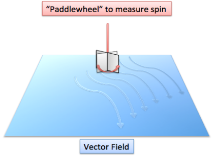
Let's use water as an example. Suppose we have a flow of water and we want to determine if it has curl or not: is there any twisting or pushing force? To test this, we put a paddle wheel into the water and notice if it turns (the paddle is vertical, sticking out of the water like a revolving door -- not like a paddlewheel boat):
If the paddle does turn, it means this field has curl at that point. If it doesn't turn, then there's no curl.
What does it really mean if the paddle turns? Well, it means the water is pushing harder on one side than the other, making it twist. The larger the difference, the more forceful the twist and the bigger the curl.
Also, a turning paddle wheel indicates that the field is "uneven" and not symmetric; if the field were even, then it would push on all sides equally and the paddle wouldn't turn at all.
Figure 15:
|
The fact that there is a "twist" means the field is not conservative.
A conservative field is "fair" in the sense that work needed to move from point A to point B, along any path, is the same. For example, consider a river: its field is conservative. Sure, you can get a free ride downstream, but then you have to do work to get back to your starting point. Or, you can do work to move upstream, and get a free ride back. Either way, the amount of work you "put in" is the same as what you get back.
However, in a field with curl (like a whirlpool), you can get a free ride by moving in the direction of the twist. In a whirlpool, you can get a free trip by moving with the current in a circle. If you fight the current and go the wrong way, you have to use energy with no free ride at all.
Conservative fields have zero curl: there are no free twists to push you along. Alternatively, if a field has curl, it is not conservative.
Gravity is another example of a conservative field. Technically, if you lift a rock and then let it fall, the energy you get from falling is the same as what you put in to lift the rock. Theoretically speaking, no energy was gained or lost in this transaction.
Mathematically
Curl is a vector, which means it has a both a magnitude and a direction. The magnitude is simply the amount of twisting force at a point.
By convention alone, if the paddle wheel is rotating counter clockwise, its curl vector points out of the page. This is a type of right-hand rule: make a fist with your right hand and stick out your thumb. If the circulation/pushing force follows the twisting of your fingers (counter clockwise), then the curl vector will be in the direction of your thumb.
The force vector is defined by the field we are in. No derivatives or other changes are necessary -- every point in the field has some force acting on it.
t's important to understand why we aren't using the position vector itself -- it tells us where we are, but not where we're going. We need to know our direction to see how much "push" we are getting: Knowing your position in a river isn't important -- are you going upstream or downstream, and at what angle?
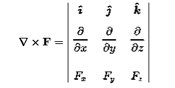
Curl of a field (F) written like this:
Curl (F) = 
Which is a cross-product of the gradient and the field (F)
|
For the conservative force the curl of that force must be equal to zero
 =0
=0
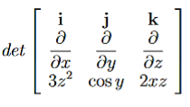
Example: Determine whether or not the following Forces are conservative? (a) F= 3z2i+ cosyj+ 2xzk (b)F=ycosxyi+xcosxyj−sinzk Solution: (a) F= 3z2i+ cosyj+ 2xzk For the conservative force the curl of that force must be equal to zero
Let us check
= 0i+ 4zj+ 0k (b)F=ycosxyi+xcosxyj−sinzk
Therefore F is conservative.
|
Central Forces
The Definition
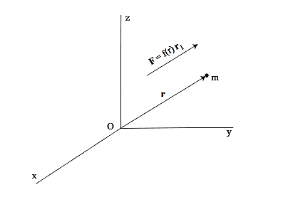
Suppose that force acting on a particle of mass m has the properties that:
•the force is always directed from m toward, or away, from a fixed point O,
•the magnitude of the force only depends on the distance r from O
Forces having these properties are called central forces. The particle is said to move in a central force field.
Figure 16:
|
Mathematically, F is a central force if and only if:
F=f(r)r1= f(r)  ………..(1)
Where r1=  is a unit vector in the direction of r.
If f(r) <0 the force is said to be attractive towards O. If f(r)>0 the force is said to be repulsive from O.
For example, the gravitational force of attraction between two point masses is a central force. The Coulomb force of attraction and repulsion between charged particles is a central force.
Properties of a Particle Moving under the Influence of a Central Force
If a particle moves in a central force field then the following properties hold:
1. The path of the particle must be a plane curve, i.e., it must lie in a plane.
2. The angular momentum of the particle is conserved, i.e., it is constant in time.
3. The particle moves in such a way that the position vector (from the point O) sweeps out equal areas in equal times. In other words, the time rate of change in area is constant. This is referred to as the Law of Areas.
Equations of Motion for a Particle in a Central Force Field
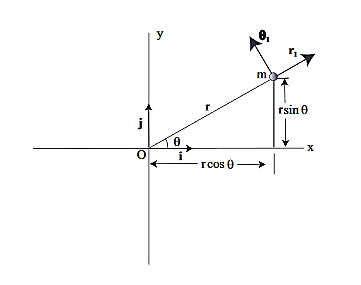
Now we will derive the basic equations of motion for a particle moving in a central force field. From Property 1 above, the motion of the particle must occur in a plane, which we take as the xy plane and the center of force is taken as the origin. In Fig. 2 we show the xy plane, as well as the polar coordinate system in the plane.
Figure 17: Polar coordinate system associated with a particle moving in the xy plane.
Since the vectorial nature of the central force is expressed in terms of a radial vector from the origin it is most natural (though not required!) to write the equations of motion in polar coordinates. In earlier lectures we derived the expression for the acceleration of a particle in polar coordinates:
Then, using Newton’s second law, and the mathematical form for the central force given in (1), we have:
These are the basic equations of motion for a particle in a central force field. They will be the starting point for many of our investigations. From these equations we can derive a useful constant of the motion. This is done as follows. From (5) we have:
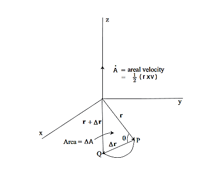
This is an interesting relation that, we will see, is related to properties 2 and 3 above. However, one use for it should be apparent. If you know the r component of the motion it allows you to compute the θ component by integration. This is another example of how constants of the motion allow us to “integrate” the equations of motion. It also explains why constants of the motion are often referred to as integrals of the motion. Now, let us return to property 3 above and derive the Law of Areas Suppose that in time ∆t the position vector moves from r to r+∆r. Then the area swept out by the position vector in this time is approximately half the area of a parallelogram with sides r and ∆r. We give a proof of this: Area of parallelogram = height×|r|,=|∆r|sinθ|r|, =|r×∆r|,
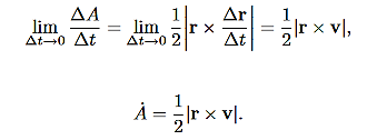
Figure 18: Hence, ∆A= Dividing this expression by ∆t, and letting ∆t→0, gives: lim∆t→0
Now we need to evaluate r×v. Using
is called the areal velocity. Alternative Forms to the Basic Equations of Motion for a Particle in a Central Force Field Recall the basic equations of motion as they will be our starting point:
We derived the following constant of the motion:
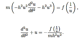
This constant of the motion will allow you to determine the θ component of motion, provided you know the r component of motion. However, (8) and (9) are coupled (nonlinear) equations for the r and θ components of the motion. How could you solve them without solving for both the r and θ components? This is where alternative forms of the equations of motion are useful. Let us rewrite (8) in the following form (by dividing through by the mass m):
Now, using (10), (11) can be written entirely in terms of r:
We can use (12) to solve for r(t), and the use (10) to solve for θ(t).Equation (12) is a non-linear differential equation. There is a useful change of variables, which for certain important central forces, turns the equation into a linear differential equation with constant coefficients and these can always be solved analytically. Here we describe this coordinate transformation. Let r = This is part of the coordinate transformation. We will also use θ as a new “time” variable. Coordinate transformation are effected by the chain rule, since this allows us to express derivatives of “old” coordinates in terms of the “new” coordinates. We have:
and
Where, in both expressions, we have used the relation r2
Substituting this relation, along with (14) into (8), gives:
Now if f(r) =
Central Force Fields are Conservative Now we will show that central forces are conservative forces. We already know that there are many important implications that will follow from this fact, such as conservation of total energy. If a central force is conservative then the work done by the force in moving a particle between two points is independent of the path taken between the two points, i.e., it only depends on the endpoints of the path. In this case we must have F.dr =-dV Where V is a scalar valued function (the potential), Evaluating the left-hand-side of this expression gives: F·dr = f(r) Also V(r) = Hence, if we know the central force field, (17) tells us how to compute the potential.
Conservation of Energy for a Particle in a Central Force Field Since central forces are conservative forces, we know that total energy must be conserved. Now we derive expressions for the total energy of a particle of mass m in a central force field. We will do this in two ways. First Method First we compute the kinetic energy. The velocity is given by:
And therefore
The kinetic energy is given by:
Therefore we have:
|
In the early 1600s, Johannes Kepler proposed three laws of planetary motion. Kepler successfully gave the three statements that described the motion of planets in a sun-centered solar system. Kepler's efforts to explain the underlying reasons for such motions are no longer accepted; nonetheless, the actual laws themselves are still considered an accurate description of the motion of any planet and any satellite.
Kepler's three laws of planetary motion can be described as follows:
- The path of the planets about the sun is elliptical in shape, with the center of the sun being located at one focus. (The Law of Ellipses)
- An imaginary line drawn from the center of the sun to the center of the planet will sweep out equal areas in equal intervals of time. (The Law of Equal Areas).
 = constant
- The ratio of the squares of the periods of any two planets is equal to the ratio of the cubes of their average distances from the sun. (The Law of Harmonies)
T2 a3
a3
Motion is always relative. Based on the energy of the particle under motion, the motions are classified into two types:
- Bounded Motion
- Unbounded Motion
In bounded motion, the particle has negative total energy (E<0) and has two or more extreme points where the total energy is always equal to the potential energy of the particle i.e the kinetic energy of the particle becomes zero.
For eccentricity 0≤ e <1, E<0 implies the body has bounded motion. A circular orbit has eccentricity e = 0 and elliptical orbit has eccentricity e < 1.
In unbounded motion, the particle has positive total energy (E>0) and has a single extreme point where the total energy is always equal to the potential energy of the particle i.e the kinetic energy of the particle becomes zero.
For eccentricity e ≥ 1, E > 0 implies the body has unbounded motion. Parabolic orbit has eccentricity e = 1 and Hyperbolic path has eccentricity e>1.
Kepler's First Law
We know that the orbit of a particle moving under attractive inverse square central force is an ellipse if its energy is negative. It is well known fact that the gravitational force between the sun and the planet is central, attractive and varies as inverse square distance. Beside the motion of the planet around the sun is bounded, so its energy is negative. Thus the orbit of the planet around the Sun must be an ellipse which is first law.
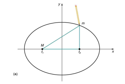
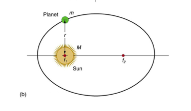
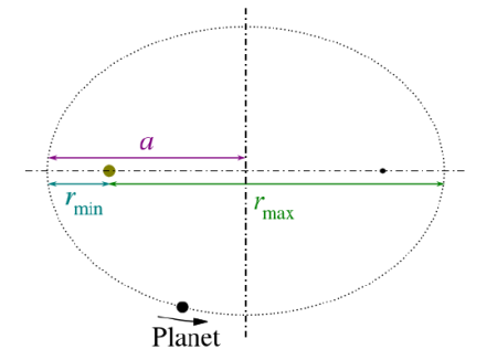
An ellipse is a closed plane curve that resembles a stretched out circle. Note that the Sun is not at the center of the ellipse, but at one of its foci. The other focal point, f2, has no physical significance for the orbit. The center of an ellipse is the midpoint of the line segment joining its focal points. A circle is a special case of an ellipse where both focal points coincide.
Figure 19(a)
|
Figure (a) An ellipse is a closed curve such that the sum of the distances from a point on the curve to the two foci (f1 and f2) is a constant. You can draw an ellipse as shown by putting a pin at each focus, and then placing a string around a pencil and the pins and tracing a line on paper. A circle is a special case of an ellipse in which the two foci coincide (thus any point on the circle is the same distance from the center).
Figure 19(b)
|
Figure 19 (b) For any closed gravitational orbit, m follows an elliptical path with M at one focus. Kepler’s first law states this fact for planets orbiting the Sun.
Kepler's Second Law
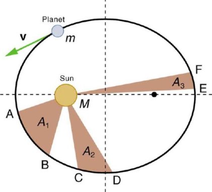
The imaginary line joining a planet and the sons sweeps equal areas of space during equal time intervals as the planet orbits. Basically, those planets do not move with constant speed along their orbits. Rather, their speed varies so that the line joining the centres of the Sun and the planet sweeps out equal parts of an area in equal times. The point of nearest approach of the planet to the Sun is termed perihelion. The point of greatest separation is aphelion, hence by Kepler's Second Law, a planet is moving fastest when it is at perihelion and slowest at aphelion.
Consider a small wedge of the orbit traced out in time dt:
Figure 20 So the area of the wedge is
And the rate at which area is swept out on the orbit is
Now, remember the definition of Angular Momentum:
Inserting this previous equation, we get
"Equal areas in equal times" means the rate at which area is swept out on the orbit (dA/dt) is constant. |
So Kepler's Second Law Revised:
The rate at which a planet sweeps out area on its orbit is equal to one-half its angular momentum divided by its mass (the specific angular momentum). Angular momentum is conserved.
See below for an illustration of this effect. The planet traverses the distance between A and B, C and D, and E and F in equal times. When the planet is close to the Sun it has a larger velocity, making the base of the triangle larger, but the height of the triangle smaller, than when the planet is far from the Sun. One can see that the planet will travel fastest at perihelion and slowest at aphelion.
Figure 21
|
Kepler’s Second Law: The shaded regions have equal areas. It takes equal times for m to go from A to B, from C to D, and from E to F. The mass m moves fastest when it is closest to M. Kepler’s second law was originally devised for planets orbiting the Sun, but it has broader validity.
Kepler's Third Law
The squares of the orbital periods of the planets are directly proportional to the cubes of the semi major axes of their orbits. Kepler's Third Law implies that the period for a planet to orbit the Sun increases rapidly with the radius of its orbit. Thus we find that Mercury, the innermost planet, takes only 88 days to orbit the Sun. The earth takes 365 days, while Saturn requires 10,759 days to do the same. Though Kepler hadn't known about gravitation when he came up with his three laws, they were instrumental in Isaac Newton deriving his theory of universal gravitation, which explains the unknown force behind Kepler's Third Law. Kepler and his theories were crucial in the better understanding of our solar system dynamics and as a springboard to newer theories that more accurately approximate our planetary orbits.
We can derive Kepler’s third law by starting with Newton’s laws of motion and the universal law of gravitation. We can therefore demonstrate that the force of gravity is the cause of Kepler’s laws.
Figure 22
|
Consider a circular orbit of a small mass m around a large mass M. Gravity supplies the centripetal force to mass m. Starting with Newton’s second law applied to circular motion,
Fnet=mac=m
The net external force on mass m is gravity, and so we substitute the force of gravity for Fnet:
G = m
= m
The mass m cancels, as well as an r, yielding
G =v2
=v2
The fact that m cancels out is another aspect of the oft-noted fact that at a given location all masses fall with the same acceleration. Here we see that at a given orbital radius r, all masses orbit at the same speed. This was implied by the result of the preceding worked example. Now, to get at Kepler’s third law, we must get the period T into the equation. By definition, period T is the time for one complete orbit. Now the average speed v is the circumference divided by the period—that is,
v=
Substituting this into the previous equation gives
G =
=
Solving for T2 yields
T2 = 
Or
T2 = 
Hence T2 a3
a3
- INERTIAL FRAMES OF REFERENCE
The inertia of a body is the resistance of changing its state of motion.
Uniformly moving reference frames (e.g. those considered at 'rest' or moving with constant velocity in a straight line) are called inertial reference frames.
Or
An inertial frame is defined as one in which Newton’s law of inertia holds that is anybody which isn’t being acted on by an outside force stays at rest if it is initially at rest, or continues to move at a constant velocity if that’s what it was doing to begin with.
Special relativity deals only with physics viewed from inertial reference frames.
If we can neglect the effect of the earth’s rotations, a frame of reference fixed in the earth is an inertial reference frame.
An example of a non-inertial frame is a rotating frame such as a carousel.
Let us understand it by an example; suppose a body is kept on the surface of the earth, for a person on earth it is at rest while for a person on the moon it is in motion so what is my inertial frame here?
Actually, the term inertial frame is relative i.e. first we assume a reference frame to be the inertial frame of reference. So a more general definition of an inertial frame would be: Inertial frame is at rest or moves with constant velocity with respect to my assumed inertial reference frame.
- NON-INERTIAL FRAME OF REFERENCE
A frame that is accelerated with respect to the assumed inertial frame of reference. Newton’s law will not hold true in these frames.
So in the above example if I assume earth to be an inertial reference frame then moon becomes a non-inertial reference frame as it is in accelerated motion with respect to earth. But if we want to make Newton’s law hold here we need to take some mysterious forces also known as pseudo forces.
Even though a rigid body is composed of an infinite number of particles, the motion of these particles is constrained to be such that the body remains a rigid body during the motion. In particular, the only degrees of freedom of a 2D rigid body are translation and rotation.
- Translation, rectilinear and curvilinear: Motion in which every line in the body remains parallel to its original position. The motion of the body is completely specified by the motion of any point in the body. All points of the body have the same velocity and same acceleration.
- Rotation about a fixed axis: All particles move in circular paths about the axis of rotation. The motion of the body is completely determined by the angular velocity of the rotation.
- General plane motion: Any plane motion that is neither a pure rotation nor a translation falls into this class. However, as we will see below, a general plane motion can always be reduced to the sum of a translation and a rotation.
Motion Relative to Translating Axes
Particle motion has been described using position vectors that were referred to fixed reference frames. The positions, velocities and accelerations determined in this way are referred to as absolute. Often it isn’t possible or convenient to use a fixed set of axes for the observation of motion. Many problems are simplified considerably by the use of a moving reference frame.
In the following we will restrict our attention to moving reference frames that translate but do not rotate.
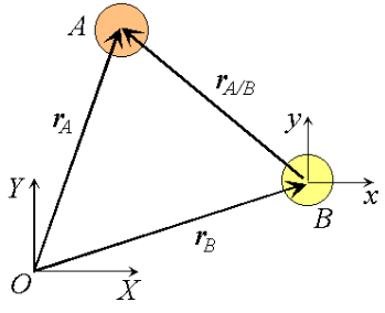
|
Figure 23 Observation of particle motion using a translating reference.
Consider two particles A and B moving along independent trajectories in the plane, and a fixed reference O. Let rA and rB be the positions of particles A and B in the fixed reference. Instead of observing the motion of particle A relative to the fixed reference as we have done in the past, we will attach a non-rotating reference to particle B and observe the motion of A relative to the moving reference at B. Let i and j be basis vectors of the moving reference, then the position vector of A relative to the reference at B, denoted rA/B is,
rA/B =xi +yj
where the subscript stands for "A with respect to B" or "A relative to B". Observe that, as the moving frame does not rotate, basis vectors i and j do not change in time. Therefore, taking time derivatives, we obtain simply,


which can be interpreted as the velocity of A relative to B. Now we can express the absolute position vector of A as,

Differentiating the equation in time to obtain expressions for the absolute velocity and acceleration of particle A:

or the absolute velocity of A equals the absolute velocity of B plus the velocity of A relative to B, vA/B , and similarly for the acceleration. The relative terms are the velocity or acceleration measured by an observer attached to the moving reference at particle B.
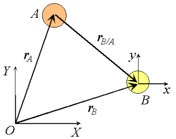
Figure 24 Relative velocities under change of translating reference.
|
What would happen if the moving reference were attached to A instead?

By comparison with expressions derived previously

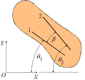
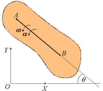
We proceed by demonstrating that every motion of a planar rigid body is associated with a single angular velocity ω and angular acceleration , describing the angular displacement of an arbitrary line inscribed in the body relative to a fixed direction.
Figure 25: Angular velocity and acceleration of a rigid body.
|
Consider a rigid body undergoing plane motion. The angular positions of two arbitrary lines 1 and 2 attached to the body are specified by  1and
1and  2 measured relative to any convenient fixed reference direction. These are related to the intermediate angle
  shown as,
 2 =
2 =  1
1
Observe that as the body is rigid, requiring that the distance between each pair of points on the two lines 1 and 2 is constant, angle  must be invariant. Differentiating the relation above with this in mind,

These hold for arbitrary lines attached to the body, implying in turn that the body can be associated with a unique angular velocity ω, defined as,

for an arbitrary line attached to the body. Arguing analogously, the body can be associated with a unique angular acceleration  defined as,

Figure 26: Angular velocity and angular acceleration of a rigid body.
|
Consequently, we have the property that all lines on a rigid body in its plane of motion have the same angular displacement, the same angular velocity ω and the same angular acceleration. 
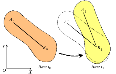
Figure 27: Decomposition of rigid body motion.
|
Next, consider the motion of a rigid body over the interval t0 - t1 as shown, with arbitrary point B0 taken as reference. Clearly, the motion can be consider to occur in two stages: a translation with reference B0 taking arbitrary line A0 B0 to an intermediate position A’B1; and a rotation about point B1 taking A’B1 to its final position A1B1. This corresponds to a decomposition of the motion into the sum of a translation and a rotation. While the translational motion is described by the velocity  and acceleration
  of the reference point, the rotational motion is characterized by the unique angular velocity ω and angular acceleration
  associated with the body. Thus, we have the property that the motion of a rigid body can be decomposed into a translation of an arbitrary point within the body, followed by a rigid rotation of the body about this point. Further, the motion of an arbitrary point within the body is determined completely once the translational quantities
  and
and  and rotational quantities ω and
  are known.
Characteristics of rigid body motion:
- All lines on a rigid body have the same angular velocity ω and the same angular acceleration
 .
. - Rigid motion can be decomposed into the translation of an arbitrary point, followed by a rotation about the point.
Now we will derive equations that describe the motion.
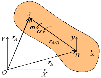
Figure 28: Definition of a translating reference attached to point B.
|
Consider a rigid body moving in the plane with angular velocity ω and angular acceleration  , and two arbitrary points A and B of the body. We will examine the motion of this body in both, the fixed reference O shown, as well as relative to a non-rotating reference attached to point B. Proceeding, we express the absolute position of point A in terms of the absolute position of point B as,

where rA/B is the position of A relative to B. An analogous expression for absolute velocities follows by taking time derivatives,

where vA/B is the velocity of point A relative to the reference at B,

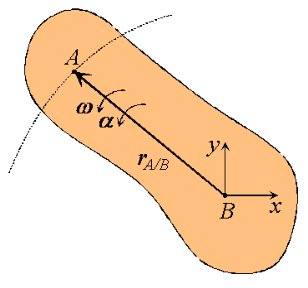
Figure 29: Motion of point A as seen by a translating observer at B. Now, as the body moves, point A traces a circular path of radius rA/B =
or,
Observe that the expression reflects the decomposition of rigid body motion referred to previously. With B chosen as reference, the velocity of A is the vector sum of a translational portion vB and a rotational portion ω Proceeding to derive expressions for the acceleration of an arbitrary point of a rigid body, we differentiate the equation for velocities to obtain,
Where
or,
Thus, like the absolute velocity, the absolute acceleration of point A is the vector sum of a translational portion |
Moment of inertia of rigid body
Rigid body is a continuous aggregation of particles. We, therefore, need to modify the summation in the expression of moment of inertia by integration as :
I = ∫r2đm
Evaluation of this integral for a given body is a separate task in itself. It is mathematically possible to evaluate this integral for bodies of regular shape. It would, however, be very difficult to evaluate the same for irregularly shaped rigid body. In such cases, it is pragmatic to resort to experimental methods to calculate moment of inertia. Mathematical evaluation of moment of inertia even for regularly shaped bodies would require specialized analysis and evaluation.
Two theorems, pertaining to moment of inertia, are of great help in the mathematical evaluation of moment of inertia of regularly shaped bodies. They are (i) parallel axes theorem and (ii) perpendicular axes theorem. These theorems extend the result of moment of inertia of basic geometric forms of rigid bodies to other axes.
Kinetic energy of rigid body in rotation
Kinetic energy of a particle or body represents the form of energy that arises from motion. We are aware that kinetic energy of a particle in translation is given by the expression:
K= mv2
mv2
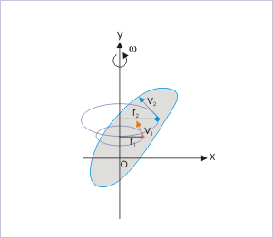
In pure rotation, however, the rigid body has no "over all" translation of the body. However, the body in rotation must have kinetic energy as it involves certain motion. A closer look on the rotation of rigid body reveals that though we may not be able to assign translation to the rigid body as a whole, but we can recognize translation of individual particles as each of them rotate about the axis in circular motion with different linear speeds. The speed of a particle is given by:
Figure 30
|
Pure rotational motion Each particle of the body follows a circular path about axis in pure rotational motion.
vi= ωri
Thus, kinetic energy of an individual particle is :
Ki= mivi2
mivi2
where " Ki" is the kinetic energy of "i" th particle having a speed " vi". In terms of angular speed, the kinetic energy of an individual particle is:
Ki= mi(ωri2
Ki= mi(ωri)2
Now, the kinetic energy of the rigid body is sum of the kinetic energies of the particles constituting the rigid body:
K=∑Ki=∑ mi(ωri)2
We note here that angular speeds of all particles constituting the body are same. Hence, the constant "1/2" and " ω2" can be taken out of the summation sign :
K = ω2∑mi(ri)2
However, we know that:
I=∑mi(ri)2
Combining two equations, we have:
K=  Iω2
Iω2
This is the desired expression of kinetic energy of a rigid body rotating about a fixed axis i.e. in pure rotational motion. The form of expression of the kinetic energy here emphasizes the correspondence between linear and angular quantities. Comparing with the expression of kinetic energy for translational motion, we find that "moment of inertia (I)" corresponds to "mass (m)" and "linear speed (v)" corresponds to "angular speed (ω)".
We can also interpret the result obtained above from a different perspective. We could have directly inferred that expression of kinetic energy in rotation should have an equivalent form as:
K (Kinetic energy)=  x(inertia)x(speed)2
In rotation, inertia to the rotation is "moment of inertia (I)" and speed of the rigid body is "angular speed (ω)". Substituting for the quantities, we have the expression for kinetic energy of rigid body in rotation as :
K=  Iω2
Iω2
Comparing this equation with the expression of the sum of kinetic energy of individual particles as derived earlier:
K = ω2∑mi(ri)2
Clearly,
I= ∑mi(ri)2
This conclusion, thus, clearly establishes that the expression as given by ∑mi(ri)2
indeed represents the inertia of the rigid body in rotation.

