Unit II
Measurement
Measurement the process of associating numbers with physical quantities and phenomena. Measurement is fundamental to the sciences; to engineering, construction, and other technical fields; and to almost all everyday activities. For that reason the elements, conditions, limitations, and theoretical foundations of measurement have been much studied. See also measurement system for a comparison of different systems and the history of their development.
Measurements may be made by unaided human senses, in which case they are often called estimates, or, more commonly, by the use of instruments, which may range in complexity from simple rules for measuring lengths to highly sophisticated systems designed to detect and measure quantities entirely beyond the capabilities of the senses, such as radio waves from a distant star or the magnetic moment of a subatomic particle. (See instrumentation.)
Measurement begins with a definition of the quantity that is to be measured, and it always involves a comparison with some known quantity of the same kind. If the object or quantity to be measured is not accessible for direct comparison, it is converted or “transduced” into an analogous measurement signal. Since measurement always involves some interaction between the object and the observer or observing instrument, there is always an exchange of energy, which, although in everyday applications is negligible, can become considerable in some types of measurement and thereby limit accuracy.
According to the National Council of Teachers of Mathematics (2000), "Measurement is the assignment of a numerical value to an attribute of an object, such as the length of a pencil. At more-sophisticated levels, measurement involves assigning a number to a characteristic of a situation, as is done by the consumer price index." An early understanding of measurement begins when children simply compare one object to another. Which object is longer? Which one is shorter? At the other extreme, researchers struggle to find ways to quantify their most elusive variables. The example of the consumer price index illustrates that abstract variables are, in fact, human constructions. A major part of scientific and social progress is the invention of new tools to measure newly constructed variables.
To be able to assign a numerical value to an attribute of an object, we must first be able to identify the attribute, and then we must have some kind of unit against which to compare that attribute. Most often we need a measurement tool that supplies us with our units. If our units are smaller than the attribute in question, then our measurement is in terms of numbers (quantities) of those units. On the other hand, if our units are larger than the attribute in question, then our measurement is in terms of parts (partitions) of the unit. Most often measurement includes a quantity of whole units along with a part of a unit. The fractional part of a unit determines the precision with which we measure. Greater precision results from smaller partitions.
The units that we use to measure are most often standard units, which means that they are universally available and are the same size for all who use them. Sometimes we measure using nonstandard units, which means that we are using units that we have invented and that are unknown outside our local context. Either standard or nonstandard units may be used in the classroom, depending on the teachers' immediate objectives.
Types of Measurement:
Generally, there are three types of measurement:
(i) Direct; (ii) Indirect; and Relative.
Direct; To find the length and breadth of a table involves direct measurement and this is always accurate if the tool is valid.
Indirect; To know the quantity of heat contained by a substance involves indirect measurement for we have to first find out the temperature of the substance with the help of a thermometer and then we can calculate the heat contained by the substance.
Relative: To measure the intelligence of a boy involves relative measurement, for the score obtained by the boy in an intelligence test is compared with norms. It is obvious that psychological and educational measurements are relative.
The measurement error is defined as the difference between the true or actual value and the measured value. The true value is the average of the infinite number of measurements, and the measured value is the precise value.
Types of Errors in Measurement
The error may arise from the different source and are usually classified into the following types. These types are
Gross Errors
Systematic Errors
Random Errors
1. Gross Errors
The gross error occurs because of the human mistakes. For examples consider the person using the instruments takes the wrong reading, or they can record the incorrect data. Such type of error comes under the gross error. The gross error can only be avoided by taking the reading carefully.
For example – The experimenter reads the 31.5ºC reading while the actual reading is 21.5Cº. This happens because of the oversights. The experimenter takes the wrong reading and because of which the error occurs in the measurement.
Such type of error is very common in the measurement. The complete elimination of such type of error is not possible. Some of the gross errors easily detected by the experimenter but some of them are difficult to find. Two methods can remove the gross error.
Two methods can remove the gross error. These methods are
- The reading should be taken very carefully.
- Two or more readings should be taken of the measurement quantity. The readings are taken by the different experimenter and at a different point for removing the error.
2. Systematic Errors
The systematic errors are mainly classified into three categories.
- Instrumental Errors
- Environmental Errors
- Observational Errors
(i) Instrumental Errors
These errors mainly arise due to the three main reasons.
(a) Inherent Shortcomings of Instruments – Such types of errors are inbuilt in instruments because of their mechanical structure. They may be due to manufacturing, calibration or operation of the device. These errors may cause the error to read too low or too high.
For example – If the instrument uses the weak spring then it gives the high value of measuring quantity. The error occurs in the instrument because of the friction or hysteresis loss.
(b) Misuse of Instrument – The error occurs in the instrument because of the fault of the operator. A good instrument used in an unintelligent way may give an enormous result.
For example – the misuse of the instrument may cause the failure to adjust the zero of instruments, poor initial adjustment, using lead to too high resistance. These improper practices may not cause permanent damage to the instrument, but all the same, they cause errors.
(c) Loading Effect – It is the most common type of error which is caused by the instrument in measurement work. For example, when the voltmeter is connected to the high resistance circuit it gives a misleading reading, and when it is connected to the low resistance circuit, it gives the dependable reading. This means the voltmeter has a loading effect on the circuit.
The error caused by the loading effect can be overcome by using the meters intelligently. For example, when measuring a low resistance by the ammeter-voltmeter method, a voltmeter having a very high value of resistance should be used.
(ii) Environmental Errors
These errors are due to the external condition of the measuring devices. Such types of errors mainly occur due to the effect of temperature, pressure, humidity, dust, vibration or because of the magnetic or electrostatic field. The corrective measures employed to eliminate or to reduce these undesirable effects are
- The arrangement should be made to keep the conditions as constant as possible.
- Using the equipment which is free from these effects.
- By using the techniques which eliminate the effect of these disturbances.
- By applying the computed corrections.
(iii) Observational Errors
Such types of errors are due to the wrong observation of the reading. There are many sources of observational error. For example, the pointer of a voltmeter resets slightly above the surface of the scale. Thus an error occurs (because of parallax) unless the line of vision of the observer is exactly above the pointer. To minimise the parallax error highly accurate meters are provided with mirrored scales.
3. Random Errors
The error which is caused by the sudden change in the atmospheric condition, such type of error is called random error. These types of error remain even after the removal of the systematic error. Hence such type of error is also called residual error.
Different Measures of Error
- Absolute Error: the amount of error in your measurement. For example, if you step on a scale and it says 150 pounds but you know your true weight is 145 pounds, then the scale has an absolute error of 150 lbs – 145 lbs = 5 lbs.
- Greatest Possible Error: defined as one half of the measuring unit. For example, if you use a ruler that measures in whole yards (i.e. without any fractions), then the greatest possible error is one half yard.
- Instrument Error: error caused by an inaccurate instrument (like a scale that is off or a poorly worded questionnaire).
- Margin of Error: an amount above and below your measurement. For example, you might say that the average baby weighs 8 pounds with a margin of error of 2 pounds (± 2 lbs).
- Measurement Location Error: caused by an instrument being placed somewhere it shouldn’t, like a thermometer left out in the full sun.
- Operator Error: human factors that cause error, like reading a scale incorrectly.
- Per cent Error: another way of expressing measurement error. Defined as:

- Relative Error: the ratio of the absolute error to the accepted measurement. As a formula, that’s:

TEMPERATURE MEASUREMENT:
Temperature is the measurement of heat (thermal energy) associated with the movement (kinetic energy) of the molecules of a substance. Thermal energy always flows from a warmer body to a cooler body. In this case, temperature is defined as an intrinsic property of matter that quantifies the ability of one body to transfer thermal energy to another body.
Temperature Scales
Several temperature scales have been developed to provide a standard for indicating the temperatures of substances. The most commonly used scales include the Fahrenheit, Celsius, Kelvin, and Rankine temperature scales. The Fahrenheit (·F) and Celsius (·C) scales are based on the freezing point and boiling point of water. The freezing point of a substance is the temperature at which it changes its physical state from a liquid to a solid. The boiling point is the temperature at which a substance changes from a liquid state to a gaseous state. To convert a Fahrenheit reading to its equivalent Celsius reading, the following equation is used.
·C = 5/9 (·F - 32)
In order to convert from Celsius to Fahrenheit, the following equation is used.
·F = 9/5 (·C) + 32
The Kelvin (K) and Rankine (·R) scales are typically used in engineering calculations and scientific research. They are based on a temperature called absolute zero. Absolute zero is a theoretical temperature where there is no thermal energy or molecular activity. Using absolute zero as a reference point, temperature values are assigned to the points at which various physical phenomena occur, such as the freezing and boiling points of water.
International Practical Temperature Scale
For ensuring an accurate and reproducible temperature measurement standard, the International Practical Temperature Scale (IPTS) was developed and adopted by the international standards community. The IPTS assigns the temperature numbers associated with certain reproducible conditions, or fixed points, for a variety of substances. These fixed points are used for calibrating temperature measuring instruments. They include the boiling point, freezing point, and triple point.
Temperature Measuring Devices
Temperature measuring devices are classified into two major groups, temperature sensors and absolute thermometers.
Sensors are classified according to their construction. Three of the most common types of temperature sensors are thermocouples, resistance temperature devices (RTDs), and filled systems. Typically, temperature indications are based on material properties such as the coefficient of expansion, temperature dependence of electrical resistance, thermoelectric power, and velocity of sound.
Calibrations for temperature sensors are specific to their material of construction. Temperature sensors that rely on material properties never have a linear relationship between the measurable property and temperature. The accuracy of absolute thermometers does not depend on the properties of the materials used in their construction.
The temperature of an object or substance can be calculated directly from measurements taken with an absolute thermometer. Types of absolute thermometers include the gas bulb thermometer, radiation pyrometer, noise thermometer, and acoustic interferometer. The gas bulb thermometer is the most commonly used. Temperature measuring devices can also be categorized according to the manner in which they respond to produce a temperature measurement. In general, the response will be either mechanical or electrical. Mechanical temperature devices respond to temperature by producing mechanical action or movement. Electrical temperature devices respond to temperature by producing or changing an electrical signal.
Temperature is defined as the energy level of matter which can be evidenced by some change in that matter. Temperature measuring sensors come in a wide variety and have one thing in common: they all measure temperature by sensing some change in a physical characteristic.
The seven basic types of temperature measurement sensors discussed here are thermocouples, resistive temperature devices (RTDs, thermistors), infrared radiators, bimetallic devices, liquid expansion devices, molecular change-of-state and silicon diodes.
1. Thermocouples
Thermocouples are voltage devices that indicate temperature measurement with a change in voltage. As temperature goes up, the output voltage of the thermocouple rises - not necessarily linearly.
Often the thermocouple is located inside a metal or ceramic shield that protects it from exposure to a variety of environments. Metal-sheathed thermocouples also are available with many types of outer coatings, such as Teflon, for trouble-free use in acids and strong caustic solutions.
2. Resistive Temperature Measuring Devices
Resistive temperature measuring devices also are electrical. Rather than using a voltage as the thermocouple does, they take advantage of another characteristic of matter which changes with temperature - its resistance. The two types of resistive devices we deal with at OMEGA Engineering, Inc., in Stamford, Conn., are metallic, resistive temperature devices (RTDs) and thermistors. In general, RTDs are more linear than are thermocouples. They increase in a positive direction, with resistance going up as temperature rises. On the other hand, the thermistor has an entirely different type of construction. It is an extremely nonlinear semi conductive device that will decrease in resistance as temperature rises.
3. Infrared Sensors
Infrared sensors are non-contacting sensors. As an example, if you hold up a typical infrared sensor to the front of your desk without contact, the sensor will tell you the temperature of the desk by virtue of its radiation–probably 68°F at normal room temperature.
In a non-contacting measurement of ice water, it will measure slightly under 0°C because of evaporation, which slightly lowers the expected temperature reading.
4. Bimetallic Devices
Bimetallic devices take advantage of the expansion of metals when they are heated. In these devices, two metals are bonded together and mechanically linked to a pointer. When heated, one side of the bimetallic strip will expand more than the other. And when geared properly to a pointer, the temperature measurement is indicated.
Advantages of bimetallic devices are portability and independence from a power supply. However, they are not usually quite as accurate as are electrical devices, and you cannot easily record the temperature value as with electrical devices like thermocouples or RTDs; but portability is a definite advantage for the right application.
5. Thermometers
Thermometers are well-known liquid expansion devices also used for temperature measurement. Generally speaking, they come in two main classifications: the mercury type and the organic, usually red, liquid type. The distinction between the two is notable, because mercury devices have certain limitations when it comes to how they can be safely transported or shipped.
For example, mercury is considered an environmental contaminant, so breakage can be hazardous. Be sure to check the current restrictions for air transportation of mercury products before shipping.
6. Change-of-state Sensors
Change-of-state temperature sensors measure just that– a change in the state of a material brought about by a change in temperature, as in a change from ice to water and then to steam. Commercially available devices of this type are in the form of labels, pellets, crayons, or lacquers.
For example, labels may be used on steam traps. When the trap needs adjustment, it becomes hot; then, the white dot on the label will indicate the temperature rise by turning black. The dot remains black, even if the temperature returns to normal.
7. Silicon Diode
The silicon diode sensor is a device that has been developed specifically for the cryogenic temperature range. Essentially, they are linear devices where the conductivity of the diode increases linearly in the low cryogenic regions.
Whatever sensor you select, it will not likely be operating by itself. Since most sensor choices overlap in temperature range and accuracy, selection of the sensor will depend on how it will be integrated into a system.
8. Radiation Pyrometers.
No contacting temperature measurement can be achieved through the use of radiation, or optical, pyrometers. The high temperature limits of radiation pyrometers exceed the limits of most other temperature sensors. Radiation pyrometers are capable of measuring temperatures to approximately 4000·C without touching the object being measured.
Factors Affecting Accuracy
There are several factors, of effects, that can cause steady state measurement errors. These effects include:
- Stem losses and thermal shunting
- Radiation
- Frictional heating
- Internal heating
- Heat transfer in surface mounted sensors
D) Pressure measurement:
Pressure is defined as force per unit area that a fluid exerts on its surroundings. Pressure, P, is a function of force, F, and area, A:
P = F/A
The SI unit for pressure is the Pascal (N/m2), but other common units of pressure include pounds per square inch (psi), atmospheres (atm), bars, and inches of mercury (in. Hg), millimeters of mercury (mm Hg), and torr.
A pressure measurement can be described as either static or dynamic. The pressure in cases with no motion is static pressure. Examples of static pressure include the pressure of the air inside a balloon or water inside a basin. Often, the motion of a fluid changes the force applied to its surroundings. For example, say the pressure of water in a hose with the nozzle closed is 40 pounds per square inch (force per unit area). If you open the nozzle, the pressure drops to a lower value as you pour out water. A thorough pressure measurement must note the circumstances under which it is made. Many factors including flow, compressibility of the fluid, and external forces can affect pressure.
Pressure measurement methods
A pressure measurement can further be described by the type of measurement being performed. The three methods for measuring pressure are absolute, gauge, and differential. Absolute pressure is referenced to the pressure in a vacuum, whereas gauge and differential pressures are referenced to another pressure such as the ambient atmospheric pressure or pressure in an adjacent vessel.
Absolute Pressure | Gauge Pressure | Differential Pressure |
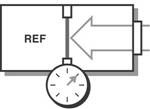 | 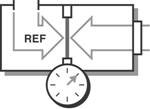 | 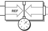 |
Figure. Pressure Sensor Diagrams for Different Measurement Methods
Absolute Pressure
The absolute measurement method is relative to 0 Pa, the static pressure in a vacuum. The pressure being measured is acted upon by atmospheric pressure in addition to the pressure of interest. Therefore, absolute pressure measurement includes the effects of atmospheric pressure. This type of measurement is well-suited for atmospheric pressures such as those used in altimeters or vacuum pressures. Often, the abbreviations Paa (Pascal’s absolute) or psia (pounds per square inch absolute) are used to describe absolute pressure.
Gauge Pressure
Gauge pressure is measured relative to ambient atmospheric pressure. This means that both the reference and the pressure of interest are acted upon by atmospheric pressures. Therefore, gauge pressure measurement excludes the effects of atmospheric pressure. These types of measurements include tire pressure and blood pressure measurements. Similar to absolute pressure, the abbreviations Pag (Pascal’s gauge) or psig (pounds per square inch gauge) are used to describe gauge pressure.
Differential Pressure
Differential pressure is similar to gauge pressure; however, the reference is another pressure point in the system rather than the ambient atmospheric pressure. You can use this method to maintain relative pressure between two vessels such as a compressor tank and an associated feed line. Also, the abbreviations Pad (Pascal’s differential) or PSID (pounds per square inch differential) are used to describe differential pressure.
How do pressure sensors work
Different measurement conditions, ranges, and materials used in the construction of a sensor lead to a variety of pressure sensor designs. Often you can convert pressure to some intermediate form, such as displacement, by detecting the amount of deflection on a diaphragm positioned in line with the fluid. The sensor then converts this displacement into an electrical output such as voltage or current. Given the known area of the diaphragm, you can then calculate pressure. Pressure sensors are packaged with a scale that provides a method to convert to engineering units. The three most universal types of pressure transducers are the bridge (strain gage based), variable capacitance, and piezoelectric.
1) Bridge-Based
All the pressure sensors, Wheatstone bridge (strain based) sensors are the most common because they offer solutions that meet varying accuracy, size, ruggedness, and cost constraints. Bridge-based sensors can measure absolute, gauge, or differential pressure in both high- and low-pressure applications. They use a strain gage to detect the deformity of a diaphragm subjected to the applied pressure.
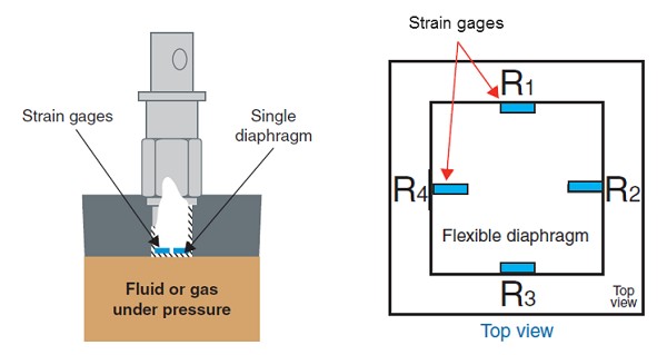
Figure Cross Section of a Typical Bridge-Based Pressure Sensor
When a change in pressure causes the diaphragm to deflect, a corresponding change in resistance is induced on the strain gage, which you can measure with a conditioned DAQ system. You can bond foil strain gages directly to a diaphragm or to an element that is connected mechanically to the diaphragm. Silicon strain gages are sometimes used as well. For this method, you etch resistors on a silicon-based substrate and use transmission fluid to transmit the pressure from the diaphragm to the substrate.
2) Capacitive Pressure Sensors
A variable capacitance pressure transducer measures the change in capacitance between a metal diaphragm and a fixed metal plate. The capacitance between two metal plates changes if the distance between these two plates changes due to applied pressure.
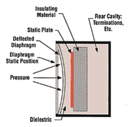
Figure Capacitance Pressure Transducer
3) Piezoelectric Pressure Sensors
Piezoelectric sensors rely on the electrical properties of quartz crystals rather than a resistive bridge transducer. These crystals generate an electrical charge when they are strained. Electrodes transfer the charge from the crystals to an amplifier built into the sensor. These sensors do not require an external excitation source, but they are susceptible to shock and vibration.
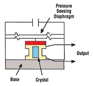
4) Conditioned Pressure Sensors
Sensors that include integrated circuitry, such as amplifiers, are referred to as amplified sensors. These types of sensors may be constructed using bridge-based, capacitive, or piezoelectric transducers. In the case of a bridge-based amplified sensor, the unit itself provides completion resistors and the amplification necessary to measure the pressure directly with a DAQ device. Though excitation must still be provided, the accuracy of the excitation is less important.
5) Optical Pressure Sensors
Pressure measurement using optical sensing has many benefits including noise immunity and isolation. Read Fundamentals of FBG Optical Sensing for more information about this method of measurement.
E) Velocity measurement:
The velocity of an object is the rate of change of its position with respect to a frame of reference, and is a function of time. Velocity is equivalent to a specification of an object's speed and direction of motion (e.g. 60 km/h to the north). Velocity is a fundamental concept in kinematics, the branch of classical mechanics that describes the motion of bodies.
The methods of measuring the velocity of liquids or gases can be classified into three main groups: kinematic, dynamic and physical.
In kinematic measurements, a specific volume, usually very small, is somehow marked in the fluid stream and the motion of this volume (mark) is registrated by appropriate instruments. Dynamic methods make use of the interaction between the flow and a measuring probe or between the flow and electric or magnetic fields. The interaction can be hydrodynamic, thermodynamic or magneto hydrodynamic.
For physical measurements, various natural or artificially organized physical processes in the flow area under study, whose characteristics depend on velocity, are monitored.
Kinematic Methods
The main advantage of kinematic methods of velocity measurements is their perfect character, and also their high space resolution. By these methods, we can find either the time the marked volume covers a given path, or the path length covered by it over a given time interval. The mark can differ from the surrounding fluid flow in temperature, density, charge, degree of ionization, luminous remittance, index of refraction, radioactivity, etc.
The marks can be created by impurities introduced into the fluid flow in small portions at regular intervals. The mark must follow the motion of the surrounding medium accurately. The motion of marks is distinguished by the method of their registration, into non-optical and optical kinematic methods. In the probe non-optical method which traces thermal no uniformities, a probe consisting of three filaments located in parallel plates used. The thermal trace is registered by two receiving wires located a distance 1 from the central wire. By registering the time Δt between the pulse heat emitted from the central wire and the thermal response of the receiving wire, we can determine the velocity u = l/Δt. Depending on which receiving wire receives a thermal pulse, we can define the direction of flow.
Marks consisting of regions of increased ion content are also widely used. To create ion marks, a spark or a corona discharge or an optical breakdown under the action of high-pulse laser radiation is used. In tracing by radioactive isotopes, the marks are created by injecting radioactive substances into the fluid flow; the times of passing selected locations by the marks are registered with the help of ionizing-radiation detectors.
Optical kinematic methods use cine and still photography to follow the motion of marks. Three main types of photography are used: cine photography, still photography with stroboscopic lighting and photo tracing. In cine photography, to determine the velocity, successive frames are aligned and the distance between the corresponding positions of the mark is measured. In the stroboscopic visualization method, several positions of the mark are registered on a single frame (a discontinuous track), which correspond to its motion between successive light pulses. Two components of the instantaneous velocity vector are determined by the distance between the particle positions. Typical of the marks used are 3-5 mm aluminum powder particles or small bubbles of gas generated electrolytic ally in the circuit of the experimental plant. Of vital importance in this method is the accuracy of measurement of the time intervals between the flashes.
In the photo tracing method, the motion of the mark is recorded by projecting the image of the mark through a diaphragm (in the form of a thin slit oriented along the fluid flow) onto a film located on a drum rotating at a certain speed. The mark image leaves a trace on the film whose trajectory is determined by adding the two vectors: the vector of mark motion and the vector of film motion. The slope angle of a tangent to this trajectory is proportional to the velocity of mark motion. Further information on the photographic technique is given in the article on Tracer Methods.
Laser Doppler anemometers can also be classified as kinematic techniques (see Anemometers, Laser Doppler).
Dynamic Methods
Among the dynamic methods the most generally employed are, because of the simplicity of the corresponding instruments, the methods based on hydrodynamic interaction between the primary converter and the fluid flow. The Pitot tube is used most often (see Pitot Tube) whose function is based on the velocity dependence of the stagnation pressure ahead of a blunt body placed in the flow.
The operating principle of fiber-optic velocity converters is based on the deflection of a sensing element, in the simplest case, made in the form of a cantilever beam of diameter D and length L and placed in the fluid flow between the receiving and sending light pipe, depends on the velocity of fluid flowing around it. The change in the amount of light supplied to a receiving light-pipe is measured by a photo detector.
The upper limit of the range of velocities measured umax is limited by the value of Re = umax D/ν  50 and the frequency response is limited by the natural frequency f0 which depends on the material, diameter and length of the sensing element. However, by varying L and D, we can change the velocities over a wide range. Depending on the fluid in which measurements of umax are made, the dimensions of the sensing elements vary within the limits of 5
  D
D  50 μm, 0.25
  L
L  2.5 mm.
The tachometric methods use the kinetic energy of flow. Typical anemometers using this principle consist of a hydrometric current meter with several semi-spherical cups or an impeller with blades situated at an angle of attack to the direction of flow (see Anemometer, Vane).
Physical Methods
The physical methods of velocity measurements are, as a rule, indirect. This category includes sputter-con methods, which use the dependence of the parameters of an electric discharge on velocity; ionization methods which depend on a field of concentrated ions, produced by a radioactive isotope in the moving medium on the fluid flow velocity; the electro diffusion method which uses the influence of flow on electrode-diffusion processes; the hot-wire or hot-film anemometer; magnet to acoustic methods.
The hot-wire method is derived from the dependence of convective heat transfer of the sensing element on the velocity of the incoming flow of medium under study (see Hot-wire and Hot-film Anemometer). Its main advantage is that the primary converter has a high frequency response, which allows us to use it for measuring turbulent characteristics of the flow.
The electro diffusion method of investigation of velocity fields is based on measuring the current of ions diffusing towards the cathode and discharging on it. The dissolved substances in the electrolyte must ensure the electrochemical reaction occurring on electrodes. Two types of electrolytes are most often used: ferrocyanidic, consisting of the solution of potassium ferri and ferrocyanide K3Fe(CN)6, K4Fe(CN)6, respectively, with concentration 10−3 − 5 × 10² mole/1) and of caustic sodium NaOH (with concentration 0.5-2 mole/1) in water; trio dine, consisting the iodide solution I2 (10−4 − 10−2 mole/1) and potassium iodide KI (0.1-0.5 mole/1) in water. Platinum is used as the cathode in such systems. In velocity measurement, a sensor which is made of a glass capillary tube 30-40 μm in diameter with a platinum wire (d = 15-20 μm) soldered into it is used. The sensing element (the cathode) is the wire end facing the flow, and the device casing is the anode. The dependence between the current in the circuit and the velocity is described by the relation I = A + B  , where A and B are transducer constants defined in calibration tests.
The magneto hydrodynamic methods are based on the effects of dynamic interaction between the moving ionized gas or electrolyte and the magnetic field. The conducting medium, moving in a transverse magnetic field, produces an electric force E between the two probes placed at a distance L in the fluid flow, proportional to the magnetic field intensity H and to the flow velocity u: E = μ  . The disadvantage of the method is that it can only be used to measure a velocity averaged over the flow section, nevertheless it has found use in investigating hot and rarefied plasma media.
Among direct methods the most abundant are the acoustic, radiolocation and optical methods. In using acoustic methods for determining the velocity of the medium, we can measure either the scattering of a cluster of ultrasound waves by the fluid flow perpendicular to the cluster axis, or the Doppler shift of the frequency of ultrasound scattered by the moving medium, or the time of travel of acoustic oscillations through a moving medium. These methods have found application in studying the flows in the atmosphere and in the ocean, where the requirements for the locality of measurement are less stringent than in laboratory model experiments. To carry out precision experiments with high space and time resolution, optical methods are used—the most refined method used is laser Doppler anemometry. (see Anemometers, Laser Doppler). Laser Doppler anemometry depends on scattering from small particles in the flow and can also be considered a kinematic method (see above).
Mass Measurement
For measuring the mean-mass velocity of flows, differential pressure flow meters, Rota meters, volumetric turbine, vortices, magnetic induction, thermal, optical and other flow meters are used in which we can define the mass velocity  = m = M/S as the flow rate M measured of the substance and by the known section of the flow S.
F) Flow strain:
The force exerted by the fluid flow on the sensors is measured using strain gauges. Multidirectional fluid flow measurement has been made possible by vectorial addition of the orthogonal flow components. The fluid speed and direction are generated irrespective of each other.
Electrical resistance strain gauges are used as the force measuring device for the first version of the flow meter. These strain gauges are bonded to the four longitudinal surfaces of a square-sectioned, elastic, rubber cantilever having a drag element attached to its free end. An attempt has been made to optimise the shape and dimensions of the elastic beam to obtain a constant drag co-efficient over a wide flow range. Calibration of the electrical strain gauge flow sensor has been performed in a wind tunnel to measure air flow. The sensor has a repeatability of 0.02%, linearity within 2% and a resolution of 0.43 m/s. The most noteworthy feature of the flow sensor is its quick response time of 50 milliseconds. The sensor is able to generate a measurement of flow direction in two dimensions with a resolution of 3.6". Preliminary measurements in a water tank enabled the speed of water to be measured with a resolution of 0.02 m/s over a range from 0 to 0.4 m/s.
An optical fibre strain sensor has been designed and developed by inserting grooves into a multimode plastic optical fibre. As the fibre bends, the variation in the angle of the grooves causes an intensity modulation of the light transmitted through the fibre. A mathematical model has been developed which has been experimentally verified in the laboratory.
The electrical strain gauge was replaced by the fibre optic strain gauge in the second version of the flow sensor. Two dimensional flow measurements were made possible by attaching two such optical fibre strain gauges on the adjacent sides of the square sectioned rubber beam. The optical fibre flow sensor was successfully calibrated in a wind tunnel to generate both the magnitude and direction of the velocity of air. The flow sensor had a repeatability of 0.3% and measured the wind velocity up to 30 M/s with a magnitude resolution of 1.3 m/s and a direction resolution of 5.9'.
The third version of the flow sensor has used the grooved optical fibre strain sensor by itself without the rubber beam to measure the fluid flow. Wind tunnel calibration has been performed to measure two dimensional wind flows up to 35 m/s with a resolution of 0.96 m/s.
A force is defined as the reaction between two bodies. This reaction may be in the form of a tensile force (pull) or it may be a compressive force (push). Force is represented mathematically as a vector and has a point of application. Therefore the measurement of force involves the determination of its magnitude as well as its direction. The measurement of force may be done by any of the two methods.
i) Direct method: This involves a direct comparison with a known gravitational force on a standard mass example by a physical balance.
Ii) ii) Indirect method: This involves the measurement of the effect of force on a body. For example.
a) Measurement of acceleration of a body of known mass which is subjected to force.
b) Measurement of resultant effect (deformation) when the force is applied to an elastic member.
A Force Gauge is measuring instrument used across all industries to measure the force during a push or pull test. Applications exist in research and development, laboratory, quality, production and field environment. There are two kinds of force gauges today: mechanical and digital force gauges.
A digital force gauge is basically a handheld instrument that contains a load cell, electronic part, software and a display. A load cell is an electronic device that is used to convert a force into an electrical signal. Through a mechanical arrangement, the force being sensed deforms a strain gauge. The strain gauge converts the deformation (strain) to electrical signals. The software and electronics of the force gauge converts the voltage of the load cell into a force value that is displayed on the instrument.
Test units of force measurements are most commonly newton’s or pounds. The peak force is the most common result in force testing applications. It is used to determine if a part is good or not. Some examples of force measurement: door latch, quality of spring, wire testing, strength but most complicated tests can be performed like peeling, friction, texture.
Digital force gauges use strain gauge technology to measure forces. The principle is as follows:
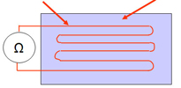
The strain gauge A strain gauge is composed of a resistive track and a deformable support. | |
Resistive track | Deformable body |
 | |
Body deformation | |
 | |
 If the body is deformed, as above in traction, the length of the resistive track increases. Consequently, its resistance increases. | |
| |
The Wheatstone Bridge
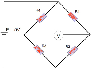
To measure the change in force, the change in resistance of the strain gauges is measured. To carry out this measurement, we use an electrical arrangement called a Wheatstone bridge as shown opposite. This circuit is in fact composed of 4 strain gauges placed in parallel in order to have a better linearity of the measurement.
Powered under constant voltage, the variation of the strain gauges varies the voltage measured by the Voltmeter on the diagram above. The value measured by V is proportional to the variation of the strain gauges according to the following formula:
V = (E x (R1 / (R1 + R4)) - E x (R2 / (R2 + R3))
Torque Measurement
Torque can be divided into two major categories, either static or dynamic. The methods used to measure torque can be further divided into two more categories, either reaction or in-line. Understanding the type of torque to be measured, as well as the different types of torque sensors that are available, will have a profound impact on the accuracy of the resulting data, as well as the cost of the measurement.
In a discussion of static vs. Dynamic torque, it is often easiest start with an understanding of the difference between a static and dynamic force. To put it simply, a dynamic force involves acceleration, were a static force does not.
The relationship between dynamic force and acceleration is described by Newton’s second law; F=ma (force equals mass times acceleration). The force required to stop your car with its substantial mass would a dynamic force, as the car must be decelerated. The force exerted by the brake caliper in order to stop that car would be a static force because there is no acceleration of the brake pads involved.
Torque is just a rotational force, or a force through a distance it is considered static if it has no angular acceleration. The torque exerted by a clock spring would be a static torque, since there is no rotation and hence no angular acceleration. The torque transmitted through a cars drive axle as it cruises down the highway (at a constant speed) would be an example of a rotating static torque, because even though there is rotation, at a constant speed there is no acceleration.
The torque produced by the car’s engine will be both static and dynamic, depending on where it is measured. If the torque is measured in the crankshaft, there will be large dynamic torque fluctuations as each cylinder fires and its piston rotates the crankshaft.
If the torque is measured in the drive shaft it will be nearly static because the rotational inertia of the flywheel and transmission will dampen the dynamic torque produced by the engine. The torque required to crank up the windows in a car would be an example of a static torque, even though there is a rotational acceleration involved, because both the acceleration and rotational inertia of the crank are very small and the resulting dynamic torque (Torque = rotational inertia x rotational acceleration) will be negligible when compared to the frictional forces involved in the window movement
Torque is measured by either sensing the actual shaft deflection caused by a twisting force, or by detecting the effects of this deflection. The surface of a shaft under torque will experience compression and tension. To measure torque, strain gage elements usually are mounted in pairs on the shaft, one gauge measuring the increase in length (in the direction in which the surface is under tension), the other measuring the decrease in length in the other direction.
Early torque sensors consisted of mechanical structures fitted with strain gages. Their high cost and low reliability kept them from gaining general industrial acceptance. Modern technology, however, has lowered the cost of making torque measurements, while quality controls on production have increased the need for accurate torque measurement.
Torque Applications
Applications for torque sensors include determining the amount of power an engine, motor, turbine, or other rotating device generates or consumes. In the industrial world, ISO 9000 and other quality control specifications are now requiring companies to measure torque during manufacturing, especially when fasteners are applied. Sensors make the required torque measurements automatically on screw and assembly machines, and can be added to hand tools. In both cases, the collected data can be accumulated on data loggers for quality control and reporting purposes.
Other industrial applications of torque sensors include measuring metal removal rates in machine tools; the calibration of torque tools and sensors; measuring peel forces, friction, and bottle cap torque; testing springs; and making biodynamic measurements.
A Vernier caliper is a measuring device used to precisely measure linear dimensions. In other words, it measures a straight line between two points.
However, it is also a very useful tool to use when measuring the diameter of a round objects like cylinders because the measuring jaws can be secured on either side of the circumference.
The Vernier Caliper is a precision instrument that can be used to measure internal and external distances extremely accurately. The example shown below is a manual caliper. Measurements are interpreted from the scale by the user. This is more difficult than using a digital vernier caliper which has an LCD digital display on which the reading appears. The manual version has both an imperial and metric scale.
Manually operated vernier calipers can still be bought and remain popular because they are much cheaper than the digital version. Also, the digital version requires a small battery whereas the manual version does not need any power source.
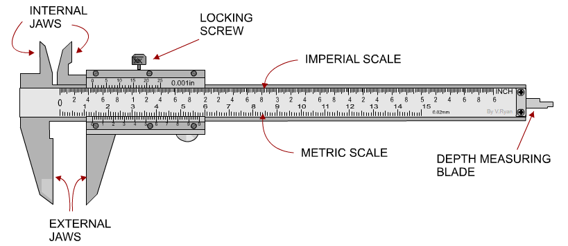
Vernier calipers have both a fixed main scale and a moving vernier scale. The main scale is graduated in either millimetres or tenths of an inch. The vernier scale allows much more precise readings to be taken (usually to the nearest 0.02mm or 0.001 inch) in comparison to a standard ruler (which only measures to the nearest 1mm or 0.25 inch).
Vernier calipers have both a fixed main scale and a moving Vernier scale. The main scale is graduated in either millimetres or tenths of an inch. The vernier scale allows much more precise readings to be taken (usually to the nearest 0.02mm or 0.001 inch) in comparison to a standard ruler (which only measures to the nearest 1mm or 0.25 inch).
Vernier calliper is an instrument that is used to measure the distance extremely accurately with error as little as0.05mm
Parts of the Vernier calliper
The various parts of the instrument is as follows
1. Main scale
2. Venire scale
3. Inner measuring jaws
4. Depth measuring prong
Least count of the instrument is calculated as
Least count=Total Vernier Scale Division 1M.S.
The object whose diameter is to be measured is kept in between the jaws of the instrument.
Then the reading on the main scale and the venire scale is noted.
The total reading of the scale is given as follows
T.S.R.=M.S.R.+V.S.R
Before taking measurement care should be taken to make sure that there is no manufacturing error in the device. This is done my checking the zero of the main scale should coincide with the zero of the venire scale.
Micrometer, in full Micrometer caliper, instrument for making precise linear measurements of dimensions such as diameters, thicknesses, and lengths of solid bodies; it consists of a C-shaped frame with a movable jaw operated by an integral screw. The fineness of the measurement that can be made depends on the lead of the screw—i.e., the amount the spindle moves toward or away from the anvil in one revolution and the means provided for indicating fractional parts of a revolution. The accuracy of the measurements depends on the accuracy of the screw-nut combination.
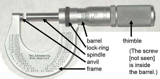
A micrometer is a precision measuring instrument, used to obtain very fine measurements and available in metric and imperial versions. Metric micrometres typically measure in 0.01mm increments and imperial versions in 0.001 inches.
Measuring using Micrometer
They are widely used in mechanical engineering for precisely measuring components. Micrometer has two scales: a primary scale, on the barrel or sleeve, and a secondary scale, on the thimble.
Values are taken from each of these scales and combined to make the total measurement.
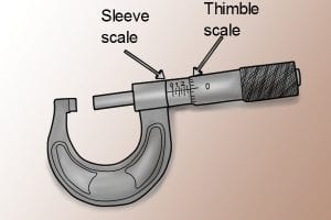
There are several types of micrometers that are designed to measure different types of objects or spaces. Most micrometers are available in sets to accommodate measurements of varying size.
Outside Micrometer: This type of micrometer is designed for measuring the outside of objects—the outside diameter (OD). They look and move much like a C-clamp, which opens and closes by turning an internal screw. In a micrometer, the object you wish to measure is clamped between the anvil (the stationary end of the clamp) and the spindle (the moving part of the clamp). Once the object is secured in the clamp, you use the numbering system on the thimble (the handle portion) to find your measurement.
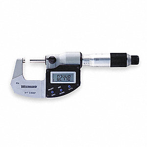
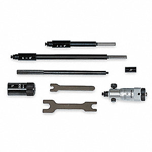
Inside Micrometer: While the outside micrometer is used for measuring the outer diameter of an object, the inside micrometer is used to measure the inside, or inside diameter (ID). These look more like a pen, but with a thimble in the middle that turns. As the thimble turns, the micrometer expands like a curtain rod would. This then extends until each end of the tool is touching the inside of the pipe. When this happens, you use the numbering system on the thimble to find your measurement.
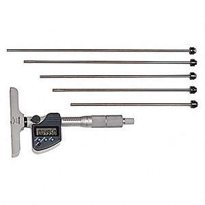
Depth Micrometers: While inside and outside micrometers are both used to measure the diameter of an object or hole, a depth micrometer is for measuring the depth of a hole, recess or slot. Depth micrometers have a base that aligns with the top of the recess that needs to be measured. The thimble is on a shaft that sticks up from the base. As the thimble turns, a measurement rod comes down from the shaft. You continue to turn until the rod hits the bottom surface of the hole being measured. When this happens you use the numbering system on the thimble to find your measurement.
The Dial Indicator is a mechanical device that consists of pinions, gears or levers. By the means of a dial indicator precision of a workpiece can be measured by an engineer. Construction of a Dial indicator changes regarding their categories. As an example, engineers often use two types of dial indicators such as Sector shape and Circular shape. But the Sector type dial indicators are not useful for measuring any tool or workpiece. It is often used by engineers to make the most accurate measurement. Also, the Sector type dial indicators are quite limited in range.
Some of the major parts of a Dial Indicator are as follows:
- A dial with the incorporation of the main scale.
- The plunger (spindle).
- Indicator (Needle).
- Locking screw or Locknut.
- Mini dial that represents the number the revolutions.
- Magnification mechanism.
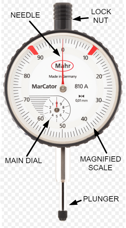
Outer parts of a dial indicator
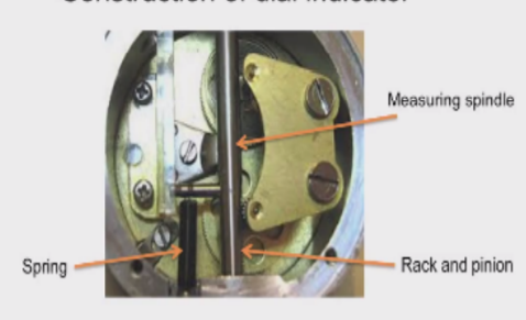
Inner parts of a dial indicator
Types of Dial indicators:
Types of dial indicators several different types of dial indicators exist, differentiated by factors such as their size, connection method and the type of information featured on their face.
- Balanced reading dial indicators
- Continuous Dial Indicators
- Reversed Balanced Dial Indicators
- Reversed Continuous Dial Indicators
- Test Dial Indicators
- Plunger Dial Indicator
- Lever Dial Indicator
Balanced reading dial indicators –Balanced reading dial indicators are so named for the way that information is arranged upon the dial’s face. Figures are printed upon the face of this dial running in two directions, starting from a zero in the Center. Often, positive numbers are featured to the right of the zero and negative numbers to the left.
Continuous Dial Indicators –Continuously numbered dial indicators do not have the two sets of numbers featured on balanced reading dial indicators. The figures on this type of dial indicators run in one direction without stopping and without any type of a separation.
Reversed Balanced Dial Indicators – Reversed Balanced Dial Indicators are named because they have the same basic positive and negative scales to each side of a zero, but the positive numbers are to the left and the negative are to the right.
Reversed Continuous Dial Indicators – Reversed continuous, or counter-clockwise, dial indicators are the same as continuous dial indicators except that the numbers run in the opposite direction.
Plunger Dial Indicator – Plunger Dial Indicator also have a clock-like face but are characterized by the plungers mounted on one of their sides. One common use for plunger dial indicators is to measure the work of injection molding machines. The mechanism which allows this type of dial indicator to work is a rack and pinion, which changes the linear thrust of the plunger into rotary motion for the dial.
Lever Dial Indicator – Lever Dial Indicator are characterized by their lever and scroll mechanisms, which cause the stylus to move. This type of dial indicators are more compact and easier to use than plunger-type dial indicators and are therefore quite often used.
Working principle Gear pinions Dial Indicators:
The working principle of the Dial Indicators is that the movement of the spindle multiplied with the reading of the main scale due to the indication of the needle. In addition to this, at the main scale rotation of pinions and gears is indicated. The plunger which meshes with P1 and G1. G1 will mesh with gears and pinions to enhance accuracy. P3 will be connected with the needle and thus it will show the deflection.
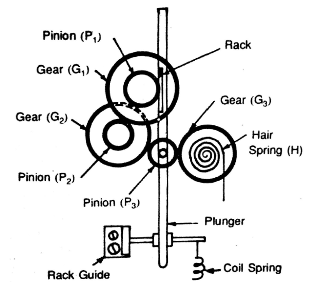
Gear pinion type dial indicator
Working principle of Lever Dial Indicators: It is a simple type of Dial Indicators. A single lever is connected and pivoted at the point. Although in the case of compound level dial indicator multiple levers are concentrated in a single point. Therefore, a fork joint is created. That is why this type of mechanism is difficult to develop.
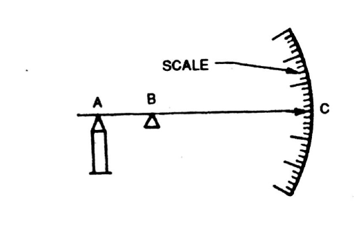
Single lever-type dial indicator
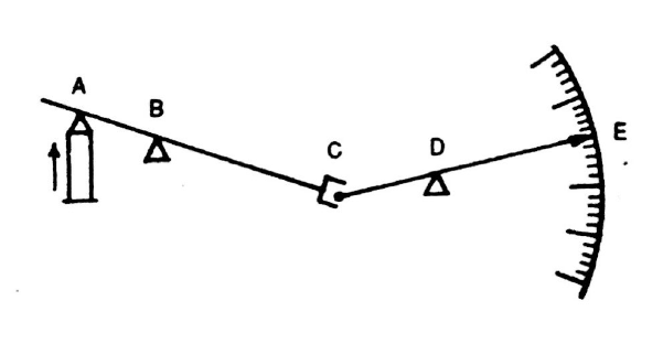 Compound lever-type dial indicator
Application of Dial Indicators:
Dial indicators are used in enormous ways by engineers, some of them are given below briefly:
- Dial indicators are used to align a workpiece in a machine. Such as, in the case of EDM, grinding machine, lathe machine, and milling machine.
- The tools are also used to check out the run out of the spindle in a machine tool.
- Workpiece can be aligned in the spin fixture by the help of Dial Indicators.
- It is also used to measure surface roughness.
- Dial indicators are used to measure parting lines in injection molding.
- It is useful to measure pit depth in EDM (Mold making resource, 2020).
- Dial indicators are efficient to measure height difference on a surface plate.
- Along with that, the tools are also very efficient to align a fixture in 5 axes milling machines.
- Dial indicators are used by engineers to inspect the precision of a workpiece in a grinding machine.
Advantages of Dial Indicators:
Some of the most effective advantages of Dial Indicators are given below:
- Dial indicator is the most flawless tool in taking linear measurements.
- The tool is very efficient to assure the quality of a workpiece
- Due to small tolerances, the size of the tool is very compact and thus, it can be used seamlessly in mass production.
- Dial indicator is also useful in dimension control.
- Moreover, Dial Indicators are also be used to measure several deviations by aligning with some other attachments.
- Out of roundness, the amount of tapper can also be measured efficiently by Dial Indicators.
Disadvantages of Dial Indicators:
Here are some disadvantages of dial indicators:
- The precision of Dial Indicators often lost due to the vibration of machinery.
- Space constraints can lead to installing the tool at an angle due to which precision of the measuring device lost.
- Another crucial disadvantage of the tool is the parallax effect.
- End float can act as a devil for Dial Indicators. In the case of journal bearings and sleeve bearing, some amount of axial play seems to be incorporated. Therefore, its impact on the accuracy level of Dial Indicators.
Slip gauges are rectangular blocks of steel having a cross section of 30 mm face length and 10 mm face width, and are most commonly used end standards in engineering practice. The size of slip gauge is defined as the distance ‘l’ between two plane measuring faces. They are made up of high grade steels with a range of sizes in a set enabling dimensions to build up to 0.005 mm, 0.001 mm or 0.0005 mm according to the set chosen. Slip gauges are also manufactured from tungsten carbide, which is an extremely hard and wear resistant material.
The slip gauges are first hardened to resist wear and carefully stabilized so that they are independent of any subsequent variation in size or shape. The longer gauges in the set, and length bars are hardened only locally at their measuring ends. After being hardened, blocks are carefully finished on the measuring faces to such a fine degree of finish, flatness and accuracy that any two such faces when perfectly clean may be “wrung” together. This is accomplished by pressing the faces into contact and then imparting a small twisting motion while maintaining the contact pressure. The phenomenon of wringing occurs due to molecular adhesion between a liquid film and the mating surfaces. By wringing suitable combination of two or more gauges together any dimensions may be build up.
To reduce wear on slip gauges a pair of protector gauge blocks is used and they are wrung to the ends of slip gauge combinations. The protector gauge blocks are made of tungsten carbide or similar wear resisting material which do not wear out and protect the slip gauges from wear. They are marked with letter ‘p’ on the measuring face.
Types of Slip Gauges
Following are the three basic types of slip gauges based on form
- Rectangular Slip gauges
- Square Slip gauges
- Square with Center hole slip gauges
1) Rectangular Slip gauges:
Rectangular slip gauges are used because they are less expensive to manufacture. They are used where space is limited or where excess weight is undesirable.
2) Square Slip gauges: Square slip gauges are preferred in certain applications even though they are expensive. Due to their large surface area they adhere better to each other when wrung to build long lengths. Further they will not wear out easily
3) Square with Center hole slip gauges:
Square with Center hole slip gauges are inserted on to the tie rod to ensure that the wrung stocks do not fall apart while handling.
Major Requirements for slip gauges
Slip gauges are used to provide end standards of specific length by combining several individual slip gauges into a single gauge bar. The success of combination of slip gauges depends on formation of a bar of reasonable cohesion between individual slip gauges and its actual dimension truly representing within specific limits, and the desired nominal dimension. For achieving this, the individual slip gauges must be available in dimensions need to achieve any combination with minimum number of gauges. The accuracy with which the individual slip gauges must be attached so closely to each other, such that the length of built up combination is equal to the added size of the individual slip gauges of the assembly.
This is achieved by wringing the slip gauges. Further the attachment of individual gauges must be firm enough to permit a reasonable amount of handling as a single unit. And also it should be possible to detach all individual slip gauges so that they are re-usable without any damage to their original size or other properties.
Wringing Phenomena
The phenomenon of wringing takes place when two flat lapped surfaces are placed in contact with a sliding movement. If the surfaces are cleaned they adhere strongly when slid carefully together. Generally speaking a minute amount of grease or moisture must be present between the surfaces for them to wring satisfactorily. The phenomenon of wringing is partly due to molecular adhesion between a liquid film and the mating flat surfaces and partly by atmospheric pressure. It has been found that the gap between the two wrung flat pieces is approximately 6 nano meters, which has no effect on the total length.
The technique of wringing together two slip gauges is quite simple, provided the surfaces are clean and free from burrs. The surfaces should be washed in petrol, benzene, carbontetrachrloride or other de-greasing agents and whipped dry on a clean cloth. The one gauge is placed at right angles to the other and slid one over the other, while pressing them together, a twisting motion is applied until the gauge blocks are lined up. In this way the air is expelled from, between the gauges faces causing the two slip gauges to adhere.
Similarly, for separating the two wrung slip gauges, combined sliding and twisting motion should be used and no attempt should be made to separate them by direct pull which may damage the slip gauges.
Manufacture of Slip Gauges
The method of manufacturing slip gauges developed by National Physical Laboratory (NPL) is as follows
- Section of high grade steel gauge blocks by preliminary operations.
- Initial hardening heat treatment to increase hardness and wear resistance
- Stabilizing treatment is performed by heating and cooling the gauge blocks successively, after rough grinding all over to remove hardening stresses. The successive temperatures used in the four stages are 40 degree, 70 degree, 130 degree and 200 degree centigrade, the gauges are heated in sand cooled slowly at each stage.
- Eight gauges of one size are then mounted on a special type of magnetic chuck and spot ground on each face. A preliminary lapping operation is also carried out which makes all the gauges parallel to about 0.0002 mm and within about 0.002 mm of size.
- The final lapping process is carried out on a solid steel chuck, on which the gauges are wrung. When the gauges have been lapped in this position, all the faces will lie in one plane, which will not necessarily be exactly parallel to the place of the chuck. In order to eliminate the wedging effect, one gauge in each corner is removed and re-arranged, each gauge being turned end for end in the process. A little consideration of this re-arrangement will show that, in whichever direction the wedge may lie, there is an almost equally high spot at each corner.
Further lapping produces very high degree of parallelism and equality of size between the eight gauges. Then all the eight gauges are compared with a standard equal to their nominal aggregate size.
A sine bar is used in conjunction with slip gauge blocks for precise angular measurement. A sine bar is used either to measure an angle very accurately or face locate any work to a given angle. Sine bars are made from high chromium corrosion resistant steel, and is hardened, precision ground, and stabilized.
Working Principle of Sine Bar:
The principle of operation of the sine bar is based on the law of trigonometry.
If one roller of sine bar is placed on the surface plate and the other roller is placed on the height of slip gauges, then the structure formed by the sine bar, surface plate, and slips gauges forms a triangle. The hypotenuse of this triangle is the sine bar, perpendicular is formed by combination of slip gauges and the surface plate is the base.
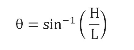
Suppose the height of slip gauges is H and the length of the sine bar is L, then sine ratio the angle theta will be H divided by L.
Now the angle θ can be calculated as sin inverse of H divided by L.
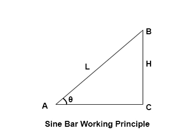

Construction of Sine Bar:
A sine bar consists of a ground body made with hardened material like steel. Two rollers are attached at the end of the steel bar. The rollers are of equal diameters and axes of these rollers are parallel to each other.
The top of the steel bar is parallel to the line through the centres of two rollers.
The length of the sine bar is equal to distance between centres of two rollers.
This length of the sine bar is 100 mm, 200mm or 300 mm.This length is very precise and accurate. Relief holes are provided just to minimize the weight of sine bar.
Only a sine bar alone can’t be used for measurement of angles of a component. The sine bar is always used in association with slip gauges and height gauge for measurement of the angles.
Surface Plate:
A surface plate is used as the base for the arrangement of sine bar and other components like slip gauges and height gauge.It can be assumed that the surface plate provides an exact horizontal surface to the sidebar. If we have a sine bar on the surface plate then the upper surface of the sine bar should be parallel to the horizontal surface of surface plate.
Dial Gauge:
A dial gauge is used to check the parallelism of a surface. If a dial gauge shows zero deflection while traveling on the surface, then we can say that the surface is parallel to its base. In the sine bar arrangement, the dial gauge is used to check whether the upper surface of the workpiece is parallel to the surface plate or not to measure the angle of tapered side of the workpiece.
Block Gauges or Slip Gauges:
Block Gauges or Slip Gauges are the standards for measuring the height or length of an object in a very precise manner.
Vernier height gauge:
A vernier height gauge is used to measure the height of the roller of the sine bar when the angle of a large component is to be measured.
Working of Sine Bar:
Sine Bar is used in different ways for measuring angle of workpieces of different types.
Working when angle of small component is to be measured:
To measure the angle of a small component, the sine bar is set up at an approximate angle on the surface plate by placing one roller of sine bar over the suitable number of slip gauges combination.
The component whose angle is to be measured is placed over the sine bar.
A dial gauge is used to check whether the upper surface of the component is parallel to the surface plate. This dial gauge is moved over the component throughout its length.
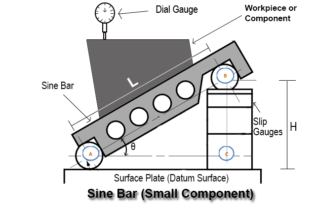
The variation in parallelism of the upper surface of the component and the surface plate can be detected by the deflection of pointer of dial gauge.
After that the height of the slip gauges are adjusted by adding or removing block of slip gauges. It is adjusted until the reading of the dial gauge becomes zero throughout the length of the component.When this condition is reached, the angle of component becomes equal to the angle of sine bar over the surface plate.
Now the angle of sine bar over surface plate can be easily measured by taking sine inverse of H divided by L, where H is the height of slip gauges and L is the length of sine bar.

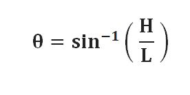
Where,
θ = angle of the component to be measured
H = height of the slip gauges
L = length of the sine bar
Working when angle of large component is to be measured:
In case of large component, the sine bar is placed over the component as the component cannot be placed over the sine bar. When the sine bar is placed over large component, the lower surface of the large component is parallel to the datum surface.
The sine bar is placed on the upper surface of the component. The upper surface of the component is inclined and its angle is to be measured. The sine bar over the upper surface is also in an inclined position and there is difference in heights of two rollers of the sine bar.
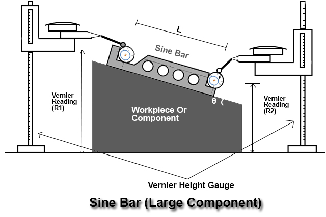
The height of the two rollers is measured using vernier height gauge and the height of two rollers is written as H1 and H2. Here the height H1 is more than H2. The difference in heights H1 and H2 is the rise of the sine-bar. The measuring pressure is also measured using a dial gauge. The height gauges are until the dial gauge reading becomes zero each time.
The angle of this large component is evaluated using the formula below:
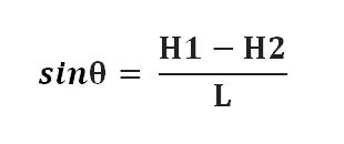
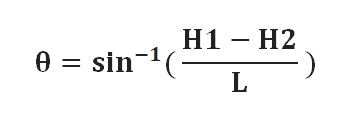
Where
θ = angle of the component to be measured
H1 = height of the upper roller
H2 = height of lower roller
L = length of the sine bar
Conditions required for accurate reading of sine bar:-
1) The axes of the two rollers of the sine bar must be parallel to each other.
2) The upper surface of the sine bar must be parallel and absolutely flat.
3) The rollers in the sine bar must be of equal diameters.
4) The distance between the centres i.e L must be accurately measured.
Types of errors in sine bar:
1) Progressive Angle Error:
This error occurs due to error in the distance of centres of two rollers.
2) Contact Angle Error:
This error occurs when the surface of the component and the roller axes are not parallel to each other.
COMBINATION SET
A combination square is a multi-use measuring instrument which is primarily used for ensuring the integrity of a 90° angle, measuring a 45° angle, measuring the centre of a circular object, find depth, and simple distance measurements. It can also be used to determine level and plumb using its spirit level vial
Terminology
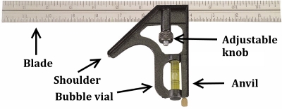
Before using a combination square, one must first be familiar with the structure and terminology of the square itself. A combination square consists of a rue-type blade attached to a handle. The handle is composed of two parts, a shoulder and an anvil. The shoulder is placed at an angle of 45° between itself and the blade. It is therefore used for the measurement and layout of miters. The anvil is placed at a 90° angle between itself and the blade. The handle contains an adjustable knob which allows it to move freely horizontally along the edge of the ruler so that it may be tailored towards any size job. Additionally contained within the head of the handle is a scriber used for marking measurements and a vial which may be used for measuring plumb and level.
Testing for Accuracy
Regardless of the job being undertaken, the first step when using a combination square is to check the square to ensure its accuracy. This task can be easily accomplished by first taping a white piece of paper to a board with a perfectly straight edge. Place the anvil of the square against this edge and draw a line on the outside edge of the blade. Once this is complete, turn over the square and draw a second line at least 1/32 in. Away from the first line drawn. If the two lines drawn are parallel with each other, then it can be said that the combination square is accurate.
To test the accuracy of the shoulder, one may simply gauge the angle it makes with the blade against a 45° drafting triangle. If the angle between the shoulder and the blade is the same as that of the triangle, then the square is accurate.
How to Use a Combination Square
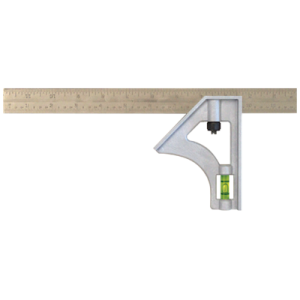
- Place the anvil of the square against the edge of the working surface you wish to cut.
- Draw a line along the blade edge until your pencil reaches the anvil of the combination square.
- Once completed, the line should be a perfect 90° angle with the edge of the working surface.
How to Use a Combination Square for Angles
- Place the shoulder of the square against the edge of the working surface you wish to cut.
- Draw a line along the blade edge until your pencil reaches the shoulder of the combination square.
- Once completed, the line should be a perfect 45° angle with the edge of the working surface.
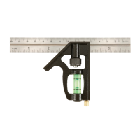
To draw a line parallel to the edge of wood being used:
- Place the anvil of the combination square along the edge of the working surface.
- Place your pencil at the end of the blade ruler.
- Put pressure on the end of the blade rule with your pencil and move the handle side along the work surface, allowing your pencil to follow with the motion of the handle.
- Once this has been done for the desired length, lift up your pencil and combination square to notice the parallel line along the working surface.
To use the blade as a normal ruler:
- Loosen the adjustable knob.
- Slide the handle off of the blade.
- Utilize the blade as a ruler.
To use the handle as a level:
- Loosen the adjustable knob.
- Slide the handle off of the blade.
- Utilize the handle as a normal level by placing the anvil side of the handle upon any surface wished to be measured.
- Read the vial to ensure levelness. If the bubble is in the middle of the vial, it is level.
To use the combination square to check for plumb:
- Place the outside edge of the blade against the vertical surface that is to be measured.
- Ensure that the bubble is in the middle of the vial.
Production Engineering:
Casting
Although casting is one of the oldest known manufacturing techniques, modern advances in casting technology have led to a broad array of specialized casting methods. Hot forming processes, such as die-casting, investment casting, plaster casting, and sand casting, each provide their own unique manufacturing benefits. Comparing both the advantages and disadvantages of the common types of casting processes can help in selecting the method best suited for a given production run.
Sand Casting
Sand casting typically relies on silica-based materials, such as synthetic or naturally-bonded sand. Casting sand generally consists of finely ground, spherical grains that can be tightly packed together into a smooth molding surface. The casting is designed to reduce the potential for tearing, cracking, or other flaws by allowing a moderate degree of flexibility and shrinkage during the cooling phase of the process. The sand can also be strengthened with the addition of clay, which helps the particles bond more closely. Automotive products such as engine blocks are manufactured through sand casting.
Sand casting involves several steps, including patternmaking, molding, melting and pouring, and cleaning. The pattern is the form around which the sand is packed, usually in two parts, the cope and the drag. After the sand is compacted enough to replicate the pattern, the cope is removed and the pattern extracted. Then, any additional inserts called core boxes are installed and the cope is replaced. After the metal has been poured and solidified, the casting is removed, trimmed of the risers and gates that were used in the pouring process, and cleaned of any adhered sand and scale.
Sand casting's main advantages as a casting process include:
- Relatively inexpensive production costs, especially in low-volume runs.
- The ability to fabricate large components.
- A capacity for casting both ferrous and non-ferrous materials.
- A low cost for post-casting tooling.
Despite its benefits, sand casting yields a lower degree of accuracy than do alternate methods and it can be difficult to sand cast components with a predetermined size and weight specifications. Furthermore, this process has a tendency to yield products with a comparatively rough surface finish.
You can use the Thomas Supplier Discovery Platform to find Sand Casting Companies for your needs.
Investment Casting
Investment, or lost-wax, casting uses a disposable wax pattern for each cast part. The wax is injected directly into a mold, removed, then coated with refractory material and a binding agent, usually in several stages to build up a thick shell. Multiple patterns are assembled onto common sprues. Once the shells have hardened the patterns are inverted and heated in ovens to remove the wax. Molten metal is then poured into the remaining shells where it hardens into the shape of the wax patterns. The refractory shell is broken away to reveal the completed casting. Investment casting is often used to manufacture parts for the automotive, power generation, and aerospace industries, such as turbine blades. Some of the central advantages and disadvantages of investment casting include:
- A high degree of accuracy and precise dimensional results.
- The ability to create thin-walled parts with complex geometries.
- The capacity for casting both ferrous and non-ferrous materials.
- Relatively high-quality surface finish and detail in final components.
Although it is highly precise, investment casting is usually more expensive than other comparable casting techniques and is typically only cost-efficient when sand or plaster castings cannot be used. However, the expense can sometimes be compensated for with reduced machining and tooling costs due to investment castings’ quality surface results.
You can use the Thomas Supplier Discovery Platform to find Investment Casting Companies for your needs.
Plaster Casting
Plaster casting is similar to the sand casting process, using a mixture of gypsum, strengthening compound, and water in place of the sand. The plaster pattern is typically coated with an anti-adhesive compound to prevent it from becoming stuck against the mold, and the plaster is capable of filling in any gaps around the mold. Once the plaster material has been used to cast the part, it usually cracks or forms defects, requiring it to be replaced with fresh material. The advantages offered by plaster casting include:
- A very smooth surface finish.
- The ability to cast complex shapes with thin walls.
- The capacity for forming large parts with less expense than other processes, such as investment casting.
- A higher degree of dimensional accuracy than that of sand casting.
This process tends to be more expensive than most sand casting operations and may require frequent replacements of the plaster molding material. It is usually more effective and cost-efficient when the quality of the surface finish is an important requirement. Its application is generally limited to casting aluminum and copper-based alloys.
You can use the Thomas Supplier Discovery Platform to find Plaster Casting Companies for your needs.
Die Casting (Metal Casting Process)
Die casting is a method of molding materials under high pressure and usually involves non-ferrous metals and alloys, such as zinc, tin, copper, and aluminum. The reusable mold is coated with a lubricant to help regulate the die’s temperature and to assist with component ejection. Molten metal is then injected into the die under high pressure, which remains continuous until the workpiece solidifies. This pressurized insertion is rapid, preventing any segment of the material from hardening before being cast. After the process is completed, the component is taken out of the die and any scrap material is removed. A few of the major advantages provided by die casting include:
- Close size and shape tolerances.
- High component dimensional consistency and uniform design.
- A reduced need for post-casting machining.
Despite its advantages, die casting as a metal casting process has relatively high tool costs, making it more cost-efficient in high-volume product runs. It can also be difficult to ensure the mechanical properties of a die-cast component, meaning these products usually do not function as structural parts. As the molds are typically two-piece, die casting is limited to products that can be removed from the mold without destroying the mold, as is done in other casting processes.
For more information on Die Casting, you can review our Types of Die Casting guide, which goes into depth on the various types, alloys, and considerations for choosing a specific process/alloy combination.
Centrifugal Casting
Centrifugal casting is used to produce long, cylindrical parts such as cast iron pipe by relying on the g-forces developed in a spinning mold. Molten metal introduced into the mold is flung against the interior surface of the mold, producing a casting that can be free of voids. Originally invented as the de Levied process using water-cooled molds, the method is applied to symmetrical parts such as soil pipe and large gun barrels and has the advantage of producing parts using a minimal number of risers. For asymmetric parts that cannot be spun around their own axes, a variant of centrifugal casting, called pressure casting, arranges several parts around a common sprue and spins the molds around this axis. A similar idea is applied to the casting of very large gear rings, etc. Depending on the material being cast, metal or sand molds may be used.
Permanent Mold Casting
Permanent mold casting shares similarities with die casting and centrifugal casting, notably the use of reusable molds. These can be made of steel, graphite, etc. and are generally used to cast materials such as lead, zinc, aluminium and magnesium alloys, certain bronzes, and cast iron. It is a low-pressure process with pouring usually done by hand using multiple molds on a turntable. As the molds rotate through the various stations they are successively coated, closed, filled, opened, and emptied. One such method is known as slush casting, where the mold is filled but emptied before the metal fully hardens. Molten metal is dumped from the casting to produce a hollow, cast shell. A similar idea is used in the molding of hollow chocolate products such as Easter bunnies. The use of metal molds induces faster heat transfer through the mold, allowing the shell to harden while the core remains liquid.
Carpentry
Carpentry may be designed as the process of making wooden articles and components such as roots, floors, partitions, doors and windows. Carpentry involves cutting, shaping and fastening wood and other materials together to produce a finished product.
Preparation of joints is one of the important operations in wood work. Joinery
Denotes connecting the wooden parts using different points such as lap joints,
Mortise and T- joints, bridle joints, etc.
Carpentry Tools
Carpentry tools are used to produce components to an exact size.
The types of carpentry tools are as follows.
1. Marking tools
2. Measuring tools
3. Holding tools
4. Cutting tools
5. Planning tools
6. Boring tools
7. Striking tools
8. Miscellaneous tools
Marking tools
It is used to marking lines parallel to the edges of a wooden piece. It consists of a square wooden stem with a sliding wooden stock on it. On the stem, a marking pin is attached which is made up of steel. This stem is provided with a steel nail to scratch the surface of the work. It consists of two pins; the distance between the pins is adjustable. It is used to draw parallel lines on the stock.
Measuring tools
The carpentry measuring tools are classified as follows
1. Steel tape
2. Steel rule
3. Caliper
Steel tapes and steel rules are mainly used for measuring short and lengths in
Millimetres a try square is used for testing squareness and marking of joints.
A meter square is used for marking and measuring an angle of 45 degree.
A bevel square is used for marking and listing angles between 0 degree to 180
Degree. Calipers are used for the precision measurement of cylindrical surface. Inside calipers are used for measuring outside diameter and outside calipers are used to measure inner diameter of a pipe.
Holding tools
The carpentry holding tools are shown in fig.

Carpentry vice
A carpentry vice is the common work holding device. It consists of one fixed jaw and one movable jaw. Its one jaw is fixed to the side of the table while the other is movable by means of a screw and a handle.
Bar clamp
The bar clamp (or) sash cramps are generally used in pairs in gluing up operations at the final assembly of joinery work. It is made up of a steel bar of T-section, wine malleable iron fittings and a steel screw.
G-clamp
G-clamp is made up of malleable iron with acme threads of high quality steel .It
Can be used for clamping small work whengluingup.
Cutting Tools
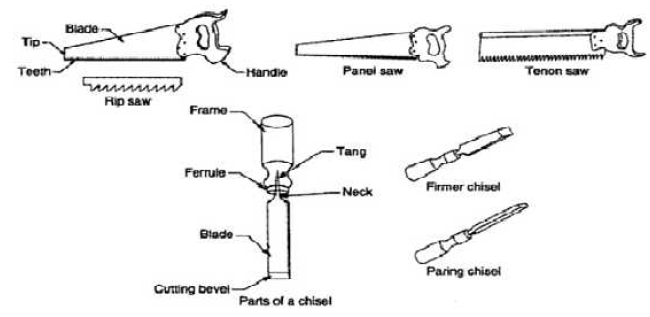
Saws
A saw is used to cut wood into pieces. There is different type of saws, designed to suit different purpose. A saw is specified by the length of its tooled edge. The
Following saws are used in the carpentry section.
Rip Saw
The blade of rip saw is either straight or skew-backed. The teeth are so set that the cutting edge of this saw makes a steeper angle about 600.
Cross Cut saw
This is similar in shape of a rip saw. It is used to cut across the grain of the stock. The correct angle for cross cutting is 450.The teeth are so set that the saw kerf is wider than the blade thickness. This allows the blade to move freely in the cut without sticking.
Tenon or back saw
A tenon saw is used for fine and accurate work. It consists of a very fine blade,
This is reinforced with a rigid steel back. The teeth are shaped like those of cross cut saw.
Chisels
Chisels are used for cutting and shaping wood accurately. Wood chisels are made in various blade widths, ranging from 3 to 50mm .Most of the wood chisels are made into tang type, having a steel shank which fits inside the handle.
Firmer chisels
These are general purpose chisels and are used either by hand pressure or by a
Mallet. The blade of a firmer chisel is flat and their sloping face is at an angle 150 to 520.
Boring Tools
Boring tools are used to make holes in wood .Common types of boring tools are as follows.
1. Bradawl
2. Gimlet
3. Brace
4. Bit and drill
A brace bolds and turns the bit and boring of a hole is obtained. A brace having
Two jaws are used for holing the bit in one end. It has two types, namely ratchet
Brace and wheel brace. A bradawl and a gimlet are used for boring small holes.
These tools are hand operated.
Striking Tools
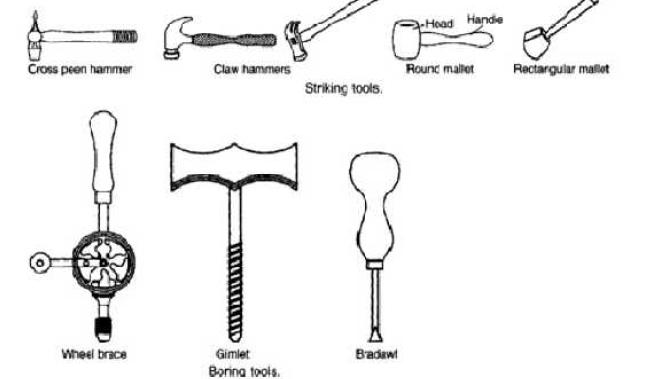
Welding
Welding is a fabrication process whereby two or more parts are fused together by means of heat, pressure or both forming a join as the parts cool. Welding is usually used on metals and thermoplastics but can also be used on wood. The completed welded joint may be referred to as a weldment
Welding is the process by which two pieces of metal can be joined together. The process of welding doesn’t merely bond the two pieces together as in brazing and soldering, but, through the use of extreme heat and sometimes the addition of other metals or gases, causes the metallic structures of the two pieces to join together and become one. There are a number of different welding methods, including spot welding, metal inert gas (MIG), and tungsten inert gas, which are forms of gas metal arc welding, arc welding, and gas welding, to name a few. Welding can even be done underwater.
There are a variety of different processes with their own techniques and applications for industry, these include:
1) Arc
This category includes a number of common manual, semi-automatic and automatic processes. These include metal inert gas (MIG) welding, stick welding, tungsten inert gas (TIG) welding also known as gas tungsten arc welding (GTAW), gas welding, metal active gas (MAG) welding, flux cored arc welding (FCAW), gas metal arc welding (GMAW), submerged arc welding (SAW), shielded metal arc welding (SMAW) and plasma arc welding.
These techniques usually use a filler material and are primarily used for joining metals including stainless steel, aluminium, nickel and copper alloys, cobalt and titanium. Arc welding processes are widely used across industries such as oil and gas, power, aerospace, automotive, and more.
Friction
Friction welding techniques join materials using mechanical friction. This can be performed in a variety of ways on different welding materials including steel, aluminium or even wood.
The mechanical friction generates heat which softens the materials which mix to create a bond as they cool. The manner in which the joining occurs is dependent on the exact process used, for example, friction stir welding (FSW), friction stir spot welding (FSSW), linear friction welding (LFW) and rotary friction welding (RFW).
Friction welding doesn't require the use of filler metals, flux or shielding gas.
Friction is frequently used in aerospace applications as it is ideal for joining otherwise 'non-weldable' light-weight aluminium alloys.
Friction processes are used across industry and are also being explored as a method to bond wood without the use of adhesives or nails.
Electron Beam
This fusion joining process uses a beam of high velocity electrons to join materials. The kinetic energy of the electrons transforms into heat upon impact with the workpiece causing the materials to melt together.
Electron beam welding (EBW) is performed in a vacuum (with the use of a vacuum chamber) to prevent the beam from dissipating.
There are many common applications for EBW, as can be used to join thick sections. This means it can be applied across a number of industries from aerospace to nuclear power and automotive to rail.
Laser
Used to join thermoplastics or pieces of metal, this process uses a laser to provide a concentrated heat ideal for barrow, deep welds and high joining rates. Being easily automated, the high welding speed at which this process can be performed makes it perfect for high volume applications, such as within the automotive industry.
Laser beam welding can be performed in air rather than in a vacuum such as with electron beam joining.
Resistance
This is a fast process which is commonly used in the automotive industry. This process can be split into two types, resistance spot welding and resistance seam welding.
Spot welding uses heat delivered between two electrodes which is applied to a small area as the work pieces are clamped together.
Seam welding is similar to spot welding except it replaces the electrodes with rotating wheels to deliver a continuous leak-free weld.
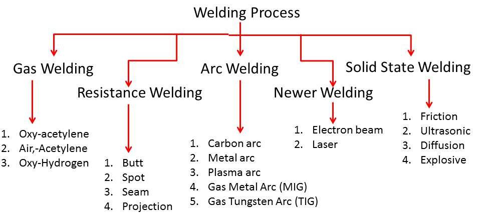
In general various welding processes are classified as follows.
1: Gas Welding
(a): Air Acetylene
(b): Oxy Acetylene
(c): Oxy Hydrogen Welding
2: Arc Welding
(a): Carbon Arc welding
(b); Plasma Arc welding
(c): Shield Metal Arc Welding
(d): T.I.G. (Tungsten Inert Gas Welding)
(e): M.I.G. (Metal Inert Gas Welding)
3: Resistance Welding:
(a): Spot welding
(b): Seam welding
(c): Projection welding
(d): Resistance Butt welding
(e): Flash Butt welding
4: Solid State Welding:
(a): Cold welding
(b): Diffusion welding
(c): Forge welding
(d): Fabrication welding
(e): Hot pressure welding
(f): Roll welding
5: Thermo Chemical Welding
(a): Thermit welding
(b): Atomic welding
6: Radiant Energy Welding
(a): Electric Beam Welding
(b): Laser Beam Welding
Welding Joints
Different type of welding joint are classified as butt, lap, Corner, tee and edge joint which are shown in figure.
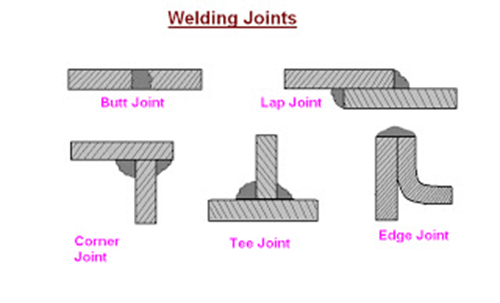
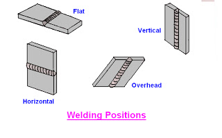
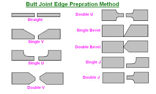
Iii) Manual metal arc welding
Manual metal arc welding (MMA or MMAW), also known as shielded metal arc welding (SMAW), flux shielded arc welding or stick welding, is a process where the arc is struck between an electrode flux coated metal rod and the work piece. Both the rod and the surface of the work piece melt to create a weld.
Manual metal arc welding was first invented in Russia in 1888. It involved a bare metal rod with no flux coating to give a protective gas shield. The development of coated electrodes did not occur until the early 1900s when the Kjellberg process was invented in Sweden and the Quasi-arc method was introduced in the UK. It is worth noting that coated electrodes were slow to be adopted because of their high cost. However, it was inevitable that as the demand for sound welds grew, manual metal arc became synonymous with coated electrodes. When an arc is struck between the metal rod (electrode) and the workpiece, both the rod and workpiece surface melt to form a weld pool of molten metal. Simultaneous melting of the flux coating on the rod will form gas and slag which protects the weld pool from the surrounding atmosphere. The slag will solidify and cool and must be chipped off the weld bead once the weld run is complete (or before the next weld pass is deposited).
The process allows only short lengths of weld to be produced before a new electrode needs to be inserted in the welding electrode holder. Weld penetration is low and the quality of the finished weld deposit is highly dependent on the skill of the welder.
MMA welding (flux-coated electrode)
An electric arc is produced between a metal electrode, carrying a high current, and the workpiece to be joined. Under the intense heat of the arc temperature (2700–5500°C), a small area of the base metal is brought to the melting point. At the same time, the end of the electrode is melted and droplets of molten metal pass through the arc to the base metal. A flux coating on the electrode provides a gaseous shielding against oxidation.
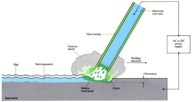

Manufacture:
- Either alternating (a.c.) or direct (d.c.) current is used for MMA welding. When a.c. Is used, the arc must re-ignite at each half-cycle, as the polarity is reversed. This causes some instability of the arc, which can be alleviated by the use of arc-stabilising agents in the flux coating. When D.C. Is used, there is a choice of polarity – the positive pole of the arc is the hottest.
- Arc voltages are maintained between 14 and 45 V, with open-circuit voltages of 50–100 V. Power sources range from 30 to 500 Amps a.c. Or d.c.
- Coated electrodes contain slag-forming ingredients (that produce a fluid coating over the weld as it cools) and gas-forming ingredients (that generate atmospheres of CO2, CO or H2 around the arc). Principal materials used in electrode coatings include:
- Carbonaceous material of the cellulose type (C6 H10 O5 ) n – produces a shielding gas (CO).
- Silica (SiO2) – combines with metallic oxides to form slag.
- Titanium oxide (TiO2) – to stabilise the arc.
- Calcium carbonate (CaCO3) – decomposes to form CaO, and hence a basic slag.
- Calcium fluoride (CaF2)– increases slag fluidity.
- Sodium oxide (Na2O) – acts as a coating binder and promotes slag fluidity.
- Ferro-silicon – acts as deoxidant.
- Iron powder – increases the rate of deposition.
- Sizes of welding machines are designated according to their output rating, which may range from 150 to 1000 Amps.
- Deposition rates in range 2–5 kg h-1.
Materials:
- Most engineering metals and alloys can be welded by the MMA welding process (very versatile process).
- In welding carbon and low alloy steels, the coated electrodes are usually of low carbon steel. For alloy steels prone to formation of hard and brittle martensite on cooling, low alloy steel electrodes are used. Also, these steels are prone to hydrogen embrittlement and coatings must be free from hydrogen-forming cellulose. Instead, TiO2 and CaCO3 are added to the coating. Austenitic compositions (up to 25% chromium and 20% nickel) are also useful to prevent martensite formation.
- Cast irons are welded with nickel-rich or monel electrodes (Ni - Cu).
- Most non-ferrous metals and alloys are welded with electrodes of a composition similar to the metal being welded. Aluminium alloy electrodes are coated with fluxes consisting of mixtures of fluorides and chlorides to dissolve the aluminium oxide Al2O3 surface layer. The precipitation hardening Al-Mg-Si alloys are now welded by the TIG and MIG processes. Copper, copper-tin (bronzes) and copper-zinc (brasses) alloys have large coefficients of thermal conductivity, so require greater amounts of heat and need pre-heating before MMA welding (up to 250–450°C). Nickel alloys can be welded with pre-heated electrodes.
Design:
- There are five main types of welded joint: butt, corner (angle), edge, fillet (or tee) and lap joints.
- Square-ended butt joints can be made in metal thicknesses up to 5mm. Single “V” butt welds are made in metal plate, with thicknesses of 5–25 mm. The minimum included angle (α) is 60° with a root opening of 0–3mm and a root face of 0–3mm.
- Fillet welds are used to fill in a corner, and are the most common welds in structural work (T-joints).
IV) Spot welding:
Spot welding (also known as resistance spot welding) is a resistance welding process. This welding process is used primarily for welding two or more metal sheets together by applying pressure and heat from an electric current to the weld area.
It works by contacting copper alloy electrodes to the sheet surfaces, whereby pressure and electric current are applied and heat is generated by the passage of current through resistive materials such as low carbon steels.
A form of resistance welding, spot welding is one of the oldest welding processes whereby two or more sheets of metal are welded together without the use of any filler material.
The process involves applying pressure and heat to the weld area using shaped alloy copper electrodes which convey an electrical current through the weld pieces. The material melts, fusing the parts together at which point the current is turned off, pressure from the electrodes is maintained and the molten “nugget” solidifies to form the joint.
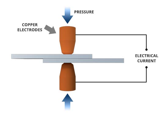
The welding heat is generated by the electric current, which is transferred to the workpiece through copper alloy electrodes. Copper is used for the electrodes as it has a high thermal conductivity and low electrical resistance compared to most other metals, ensuring that the heat is generated preferentially in the work pieces rather than the electrodes.
The amount of heat depends on the thermal conductivity and electrical resistance of the metal as well as the amount of time the current is applied. This heat can be expressed by the equation:
Q = I2Rt
In this equation “Q” is heat energy, “I” is current, “R” is electrical resistance and “t” is the time for which the current is applied.
Spot welding has applications in a number of industries, including automotive, aerospace, rail, white goods, metal furniture, electronic, medical building and construction.
Given the ease with which spot welding can be automated when combined with robots and manipulation systems, it is the most common joining process in high volume manufacturing lines and has in particular been the main joining process in the construction of steel cars for over 100 years.
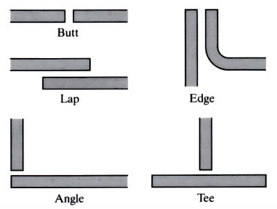

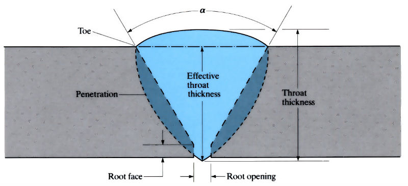

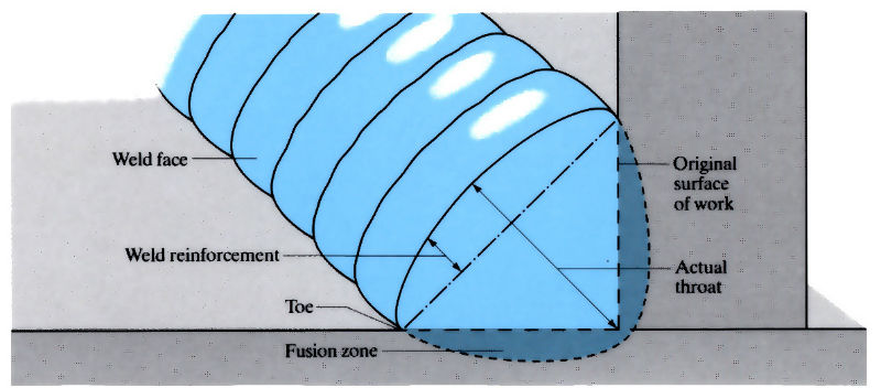

i) Oxy acetylene welding:
Oxy-Acetylene (OA) welding is one of the many types of welding. It is extremely versatile, and with enough skill and practice you can use this type of welding for virtually any metal. In fact, the oxy-acetylene flame burns at 6000 F, and is the only gas flame that is hot enough to melt all commercial metals. Oxy-acetylene welding is simple in concept - two pieces of metal are brought together, and the touching edges are melted by the flame with or without the addition of filler rod.
Advantages of Oxy-Acetylene Welding
It's easy to learn.
The equipment is cheaper than most other types of welding rigs (e.g. TIG welding)
The equipment is more portable than most other types of welding rigs (e.g. TIG welding)
OA equipment can also be used to "flame-cut" large pieces of material.
Disadvantages of Oxy-Acetylene Welding:
OA weld lines are much rougher in appearance than other kinds of welds, and require more finishing if neatness is required.
OA welds have large heat affected zones (areas around the weld line that have had their mechanical properties adversely affected by the welding process)
Materials Suitable for OA Welding
Most steels
Brass
Preparation:
1) Assemble all of the materials needed to make the weld. This includes parts, OA equipment, fixturing, tools, safety mask, gloves, and filler rod.
2) Clean the parts to be welded to remove any oil, rust, or other contaminants. Use a wire brush if needed to remove any rust.
3) Assemble and fixture the parts in place - the parts need to be stable for a good weld line. Ceramic bricks, vise grips, pliers, and clamps are available in a file cabinet in the weld room for fixturing.
4) Select the nozzle you plan to use for welding. Nozzles come in a variety of sizes, from 000 (for a very small flame - typically used for thin materials) to upwards of 3 (for a large flame - needed for thick materials). Larger nozzles produce larger flames and, in general, are more appropriate for thicker material. Choosing the right size nozzle becomes easier with more experience.
5) Clean the nozzle. Carbon deposits can build up on the nozzles which interfere with flame quality and cause backfiring. The cleaning tool has a wide flat blade (with a file-like surface) which is used to clean carbon deposits on the exterior of the nozzle. Use it to scrape any deposits from the flat face of the tip. Use the wire-like files to clean the interior of the nozzle. Pick the largest wire which will fit inside the nozzle and the scrape the edges of the hole to remove any carbon build-up.
6) Attach the nozzle to the gas feed line by hand. Don't over-torque - the nozzle and hose fitting are both made of brass which doesn't stand up well to abuse. A snug, finger tight fit is the sufficient.
7) Check the pressure levels in the oxygen and acetylene tanks. There should be at least 50 psi in the acetylene tank. The oxygen tank can be used until it is completely empty. . Note: The oxygen used in OA welding in NOT for human consumption. It contains contaminants that could be unhealthy if taken in large quantities
Adjusting the flame
The blue flame will be divided into 3 different colour regions - a long yellowish tip, a blue middle section, and a whitish-blue intense inner section.
There are three types of flames as described below:
1) Neutral - This type of flame is the one you will use most often in the metalwork room. It is called “neutral” because it has no chemical effect upon the metal during welding. It is achieved by mixing equal parts oxygen and acetylene and is witnessed in the flame by adjusting the oxygen flow until the middle blue section and inner whitish-blue parts merge into a single region.
2) Reducing / Carburising flame - If there is excess acetylene, the whitish-blue flame will be larger than the blue flame. This flame contains white hot-carbon particles, which may be dissolved during welding. This “reducing” flame will remove oxygen from iron oxides in steel.
3) Oxidizing flame - If there is excess oxygen, the whitish-blue flame will be smaller than the blue flame. This flame burns hotter. A slightly oxidizing flame is used in brazing, and a more strongly oxidizing flame is used in welding certain brasses and bronzes.
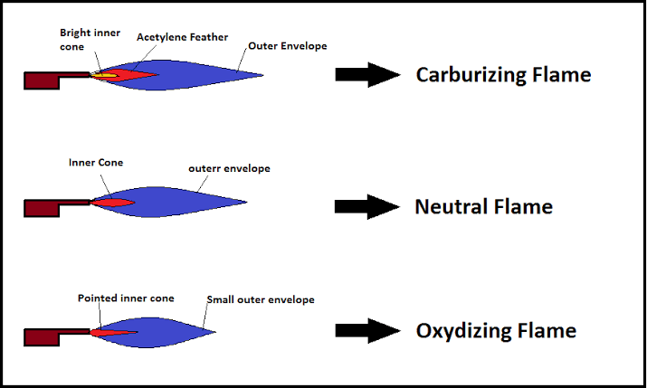
Safety features incorporated into oxy-acetylene equipment
The Acetylene tank contains an absorbent substance called Acetone. Acetone can absorb 25 times its own volume of Acetylene.
Colour coding: oxygen cylinder is black and acetylene is maroon, hoses and regulators are colour coded with oxygen as blue and acetylene as red.
The acetylene connection on the torch has a left hand thread and the oxygen connection has a right hand thread to prevent interchange.
Flashback arrestors are placed on the acetylene and oxygen lines to prevent feedback of gases.
Regulators are designed to fit only on acetylene or high pressure oxygen cylinders and cannot be changed
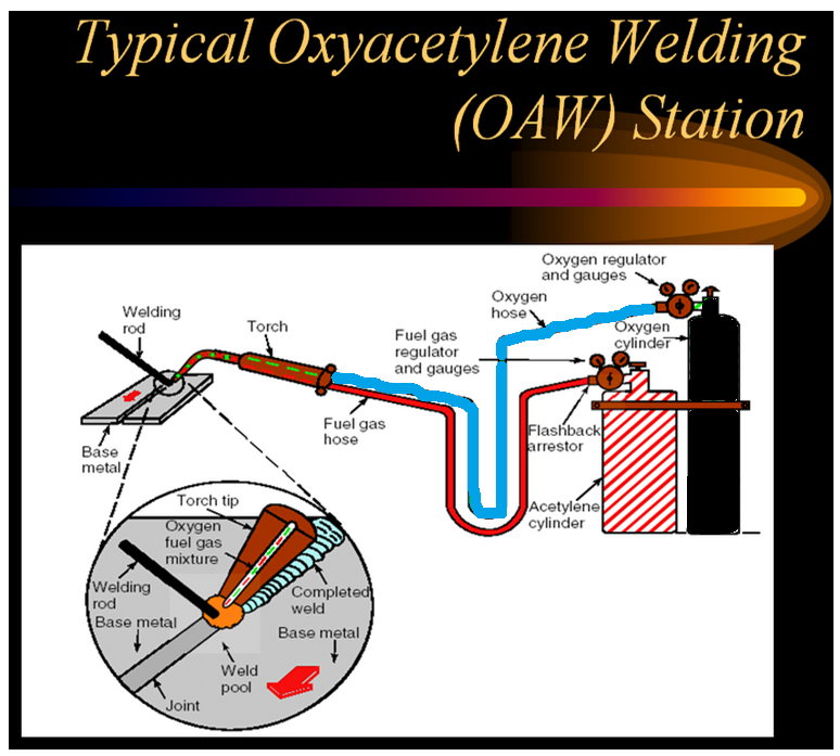
Lathe machine
Center or Engine Lathe Machine is the most widely used lathe machine and still, it is, in every workshop, this machine is present. The operation like Turning, facing, grooving, Knurling, threading and more, such operations are performed on this type of machine.
Centre lathe machine has all the parts such as bed, Saddle, headstock, and tailstock, etc. The headstock of an engine lathe is rigid and tailstock is moveable which is further used to support an operation like knurling. It can easily feed the cutting tool in both directions i.e. longitudinal and lateral directions with the help of feed mechanisms. Center Lathe machines are driven by the gear mechanism or pulley mechanism. It has three types of driven mechanisms, and those are Belt-driven, Motor-driven, gear head type.
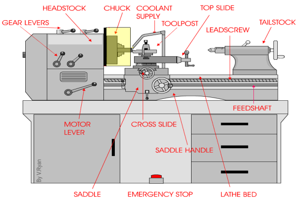
The Centre Lathe is used to manufacture cylindrical shapes from a range of materials including; steels and plastics. Many of the components that go together to make an engine work have been manufactured using lathes. These may be lathes operated directly by people (manual lathes) or computer controlled lathes (CNC machines) that have been programmed to carry out a particular task. A basic manual centre lathe is shown below. This type of lathe is controlled by a person turning the various handles on the top slide and cross slide in order to make a product / part.
The headstock of a centre lathe can be opened, revealing an arrangement of gears. These gears are sometimes replaced to alter the speed of rotation of the chuck. The lathe must be switched off before opening, although the motor should automatically cut off if the door is opened while the machine is running (a safety feature).
The speed of rotation of the chuck is usually set by using the gear levers. These are usually on top of the headstock or along the front and allow for a wide range of speeds.
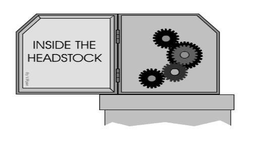
However, sometimes the only way to set the lathe to a particular speed is to change the gear arrangement inside the headstock. Most machines will have a number of alterative gear wheels for this purpose.
Ii) Basic element:
A lathe machine tool consists of several parts like:
- Headstock
- Bed
- Tailstock
- Carriage
- Saddle
- Cross-slide
- Compound rest
- Tool post
- Apron
- Lead Screw
- Feed rod
- Chuck
- Main spindle
- Leg
1) Head Stock:
Head Stock is situated at the left side of the lathe bed and it is the house of the driving mechanism and electrical mechanism of a Lathe machine tool.
- It holds the job on its spindle nose having external screw threads and internally Morse taper for holding lathe center. And it is rotating at a different speed by cone pulley or all geared drive. There is a hole throughout spindle for handling long bar work.
- Head Stock transmits power from the spindle to the feed rod, lead screw and thread cutting mechanism.
Accessories mounted on headstock spindle:
- Three jaw chuck
- Four jaw chuck
- Lathe centre and lathe dog
- Collect chuck
- Faceplate
- Magnetic chuck
A separate speed change gearbox is placed below headstock to reduce the speed in order to have different feed rates for threading and automatic lateral movement of the carriage. The feed rod is used for most turning operation and the lead screw is used for thread cutting operation.
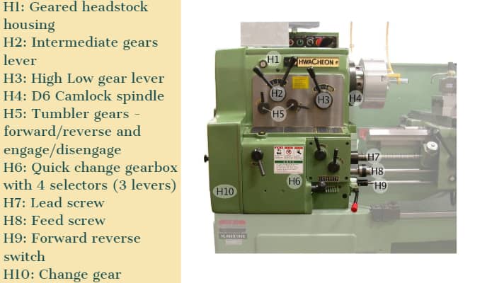
2) Bed:
It is the base of the lathe machine. It is made of single piece casting of Semi-steel (Chilled Cast Iron). The bed consists of two heavy metal slides running lengthwise, with ways or ‘V’ formed upon them and rigidly supported with cross girths.
- It is sufficiently rigid and good damping capacity to absorb vibration.
- It prevents the deflection produced by the cutting forces.
- It supports the headstock, tailstock, carriage and other components of the lathe machine.
3) Tail Stock:
Tail Stock is situated on the right side above the lathe bed. It is used for:
- Support the long end of the job for holding and minimizes its sagging.
- It holds the tool for performing different operations like drilling, reaming, tapping, etc.
- And it is also used for a small amount of taper for a long job by offsetting the tailstock.
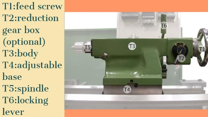
4) Carriage:
The carriage is used for support, guide and feed the tool against the job when the machining is done.
- It holds moves and controls the cutting tool.
- It gives rigid supports to the tool during operations.
- It transfers power from feed rod to cutting tool through apron mechanism for longitudinal cross-feeding.
- It simplifies the thread cutting operation with the help of lead screw and half nut mechanism.
It is consists of:
- Saddle
- Cross-slide
- Compound rest
- Tool post
- Apron
It provides three movements to the tool:
- Longitudinal feed-through carriage movement
- Cross feed-through cross slide movement
- Angular feed-through top slide movement
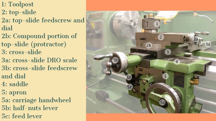
5) Saddle:
Generally, it is made up of ‘H’ shaped casting and it has a ‘V’ guide and a flat guide for mounting it on the lathe bed guide ways.
6) Cross-slide:
It is assembled on the top of the saddle. The top surface of the cross-slide is provided with T-slot.
7) Compound rest:
It supports the tool post and cutting tool in its various positions. It can be swiveled at any desired position in the horizontal plane. It is necessary for turning angles and boring short tapers.
8) Tool post:
It is the topmost portion of the carriage and it is used to hold various cutting tools or tool holders. There are three types of tool post commonly used and those are:
- Ring and rocker tool post
- Square head tool post
- Quick change tool post
9) Apron:
An apron is a house of the feed mechanism. It is fastened to the saddle and hangover in front of the bed.
10) Lead screw:
A lead screw is also known as a power screw or a translation screw. It converts rotational motion to linear motion. Lead Screw is used for Thread Cutting operation in a lathe machine tool.
11) Feed Rod:
Feed rod is used to move the carriage from the left side to the right side and also from the right side to the left side.
12) Chuck:
Chuck is used to holding the work piece securely.
There are generally 2 types of chucks:
- 3 jaw self-cantering chuck
- 4 jaw independent chuck
13) Main Spindle:
The spindle is a hollow cylindrical shaft in which long jobs can pass through it.
It is designed so well that the thrust of the cutting tool does not deflect the spindle.
14) Leg:
Legs are carrying an entire load of a lathe machine tool and transfer to the ground. The legs are firmly secured to the floor by the foundation bolt.
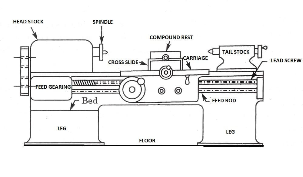
Iii) Working operation on lathe:
A Lathe Machine consists of the following operation:
1) Centering
2) Facing
3) Turning
4) Chamfering
5) Knurling
6) Thread cutting
7) Drilling
8) Boring
9) Reaming
10) Spinning
11) Tapping
12) Parting off
Before continuing any operation in lathe we have to load the job and center it on the head-stock spindle.
In latheoperations, the headstock spindle holds the job and it rotates with the same speed as the spindle. The carriage holding the tool on the tool post, also the carriage gives the tool post moves longitudinally or crosswise direction to give the desired feed on the job.
These two motions (longitudinally and crosswise) help to remove the chips of the metal and giving the proper shape of the job. The Lathe is such a versatile machine that it can produce another lathe. It is tough to mention which operations are not performed in a lathe machine tool, though we discuss some important lathe operations in detail.
1) Centering operation in the lathe:
We use this operation for producing a conical hole in the face of the job to make the bearing support of the lathe centre when the job is to hold between two canters. (Head-stock and Tail-stock)
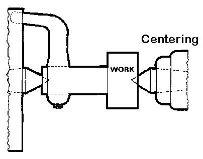 CENTERING OPERATION
2) Facing operation in the lathe:
Facing operation is for making the ends of the job to produce a smooth flat surface with the axis of operation or a certain length of a job. In this operation,
- Hold the job on Head-stock spindle using Three or four-jaw chuck.
- Start the machine on desire RPM to rotate the job.
- Give a desirable feed on the perpendicular direction of the axis of the job.
![22 Types of Lathe Machine Operations [Complete Guide] PDF](https://glossaread-contain.s3.ap-south-1.amazonaws.com/epub/1643277054_245092.jpeg)
3) Turning operation in the lathe:
The operation by which we remove the excess material from the work piece to produce a cone shaped or a cylindrical surface
There are several types of turning operations, those are:
- Straight turning
- Shoulder turning
- Rough turning
- Finish turning
- Taper turning
- Eccentric turning
Straight turning:
This operation is done to produce a cylindrical surface by removing excess material from the work piece.
It is done in the following ways:
- Mount the job by suitable job holding device and check the trueness of the job axis with the lathe axis.
- Hold the cutting tool on the tool post and set the cutting edge at the job axis or slightly above it.
- Set the spindle as per the desired feed.
- Give depth of cut as per finish or rough cut.
- Start the machining.
- Engage automatic feed to move the carriage with the tool to the desired length, then disengage the feed and carriage is brought back to its starting.
- The process is repeated until the job finished.
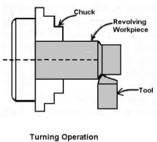
STRAIGHT TURNING OPERATION
Shoulder turning:
A shoulder turning is called which has a different diameter to form a step from one diameter to another. There are four kinds of the shoulder.
- Square
- Bevelled
- Radius
- Undercut
![22 Types of Lathe Machine Operations [Complete Guide] PDF](https://glossaread-contain.s3.ap-south-1.amazonaws.com/epub/1643277054_3920133.jpeg)
Rough turning:
It is a process of removal of excess material from the work piece in minimum time by applying a high rate of feed and heavy depth of cut.the depth of cut is around 2 to 5mm and the rate of feed is 0.3 to 1.5mm/revolution.
Finish turning:
The finish turning operation needs high cutting speed, minimum feed and a very small depth of cut to generate the smooth surface.
In finish turning the depth of cut is around 0.5 to 1mm and the rate of feed is 0.1 to 0.3 mm/revolution.
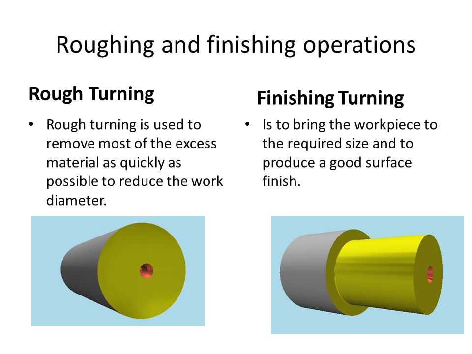
Taper turning:
A taper is defined as a uniform decrease or increase in the diameter of a work piece along with its length.
The operation by which a conical surface of the gradual reduction in diameter from a cylindrical work piece is produced is called taper turning.
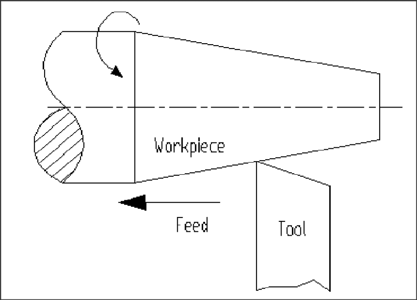
Taper turning methods:
A tapering form may be done by anyone of the following methods.
- Taper turning by form tool
- By swivelling the compound rest
- Tail-stock set over method
- By taper turning attachment
Let me discuss them in brief.
Taper turning by form tool:
It is used to form a short length of taper by using a form tool or broad nose tool.
Any increase in the length of taper will require the use of a wider cutting edge which may destroy the work piece due to the vibration and spoil the work piece. In this operation, the tool angle must be half of the taper angle.
Taper turning by swiveling the compound rest:
This method is used for turning step and short tapers.
It is done as follows:
- Set the compound rest by swiveling it from the centreline of the lathe centre through an angle equal to a half taper angle.
- Clamp the carriage in place.
- After adjusting and setting the tool, feed is applied by the compound rest’s feed handle to complete the taper.
Tail-stock set over method:
Set over of tail-stock from its centre-line is done equal to half taper.
Job is held between the centres. The length of the workpiece will be long enough. An only a small taper on a long job is done by this process.
It is used for external taper only.
By taper turning attachment:
It is done in the following ways:
- The cross slide is first made free from lead screw by hinder screw.
- The rear end of the cross slide is then tightened with a guide block by a belt.
- Set the guide bar at an angle to the lathe axis. (Half taper angle)
- The required depth of cut is given by the compound slide is at a right angle to the lathe axis.
4) Chamfering operation:
Chamfering is used for bevelling the end of a job to remove burrs, to look better, to make a passage of the nut into the bolt. This operation is done after thread cutting, knurling, rough turning.
![22 Types of Lathe Machine Operations [Complete Guide] PDF](https://glossaread-contain.s3.ap-south-1.amazonaws.com/epub/1643277054_554393.jpeg)
5) Knurling operation:
It is the process of producing a rough surface on the workpiece to provide effective gripping. Knurling tool is held rigidly on the tool post and pressed against the rotating job so that leaving the exact facsimile of the tool on the surface of the job.
![22 Types of Lathe Machine Operations [Complete Guide] PDF](https://glossaread-contain.s3.ap-south-1.amazonaws.com/epub/1643277054_6003335.jpeg)
6) Thread cutting operation:
It is the operation that is used to produce a helical groove on a cylindrical or conical surface by feeding the tool longitudinally when the job revolved between the two canters.
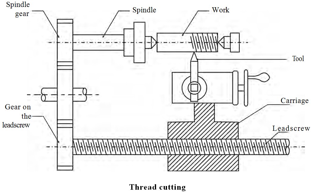
Tool setting for thread cutting operation:
The tool should be set exactly to the height of the centre line of the job and at 90 degrees to the job.
Tool setting gauge is used for this purpose.
Feeding during thread cutting operation:
It is done in two ways.
- The tool may be feed exactly at 90 degrees to the job axis but it does not have good cutting action because only the front end of the tool does cutting.
- The tool may beefed at an angle from 27-30 degrees at which the compound rest may be set so that the complete side of the tool is used for cutting action which gives a better polish on the threads.
Job speed during threading:
The job speed will be 1/3 to 1/4th of the job speed in turning operation.
7) Drilling operation:
Drilling is an operation by which we can make holes in a job.
In this operation, the job is rotated at the turning speed on the lathe axis and the drilling tool fitted on the tail-stock spindle. And the tail-stock is moved towards the job by hand feed.
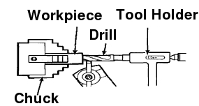
8) Boring operation:
In this operation, we can enlarge the diameter of the existing hole on a job by turning inside with some farm tool known as a boring tool. The boring tool is also fitted on tail-stock.
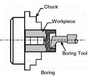
9) Reaming operation:
Reaming is the operation for sizing or finishing a drilled hole to the required size by a tool called reamer. This tool is fitted on tail-stock.
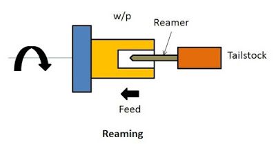
10) Spinning operation:
In this operation, the job of this sheet metal is held between the former and the tail-stock center rotates at high speed with the former.the long round nose forming tool rigidly fixed on special tool post presses the job on the periphery of the former. So the job is taken exactly the shape of the former. This is a chip less machining process.
11) Tapping operation:
We use this operation for creating internal threads within a hole by means of a tool called tap.
Three taps are generally used in an internal thread.
- Taper Tap
- Second Tap
- Plug Tap
12) Parting-off operation:
It is the operation of cutting off a bar type job after complete the machining process. In this operation a bar type job is held on a chuck, rotates at turning speed, a parting off tool is fed into the job slowly until the tool reaches the center of the job.
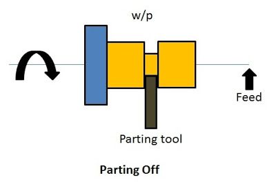
Iv) Turning and facing:
Turning:
Turning a taper on a long piece of material is best achieved by offsetting the tailstock. The material is held between two centres as a normal three jaw chuck cannot be used. A three jaw chuck will not hold the material safely or accurately when a long taper is being turned. Diagram ‘A’ below shows the side view of the two centres, the material and the tool post. |
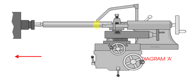 |
Diagram ‘B’ shows a bird’s eye view (plan view) of the same equipment. However, this time it can be seen that the tailstock has been adjusted so that it is off centre. This means that a long taper can be turned. A small amount of material must be removed with each pass of the cutting tool. Also the lathe should be setup so that the cutting tool feeds automatically along the bed of the lathe. This will lead to a better finish to the surface of the material. The animation below shows a 'speeded up version' of taper turning. Normally taper turning takes a long time. |
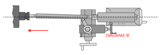 |
Diagram ‘C’ shows the scale at the back of the tailstock. To adjust the tailstock so that it is off centre usually means loosening a number of Allen screws, offsetting the tailstock and then tightening the screws back in position.
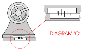
Facing:
A very basic operation is called ‘facing off’. A piece of steel has been placed in the chuck and the lathe cutting tool is used to level the end. This is done by turning the cross-slide handle so that the cross-slide moves and the cutting tool cuts the surface of the steel. |
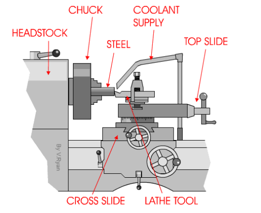 |
Only a small amount of material should be removed - each pass of the cross slide. After each pass of the cutting tool the top slide can be rotated clockwise to move the tool forward approximately 1mm.
This sequence is repeated until the steel has been levelled (faced off).
When using a centre lathe it is always advisable to work patiently and safely. Do not attempt to remove too much material in one go. At best this will caused damage to the steel being worked on and to the expensive cutting tool being used. At worse an accident will occur.
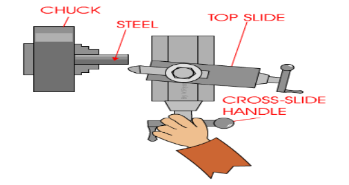
When turning a short taper the top slide is set a the required angle. This is normally done by loosening two small Allen screws and then rotating the topslide to the angle and tightening back up the two allen screws. |
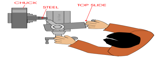 |
) Drilling machine-
Drilling Machine is the simplest, moderate, and most accurate machine tool used in almost all the production shops and tool rooms. Drilling is basically a single purpose machine tool as its main purpose is to make holes in the workpiece.
A machine consists of a spindle that provides rotary motion to the drilling tool, which finally makes the hole in the job(workpiece).
A drilling machine is a type of machine in which the holes are being made on the workpiece by making use of a rotating tool called drill bit or the twist drill. Drilling is basically a technology of creating holes.
Drilling operation can also be performed on Lathe Machine. In the lathe machine, the workpiece rotates and the drilling tool is held stationary in the tailstock.
Boring: When we talk about drilling, boring is mostly discussed.
Basically, Boring is a process in which the holes are enlarged that is already being drilled or cored. To perform boring action by a machine a special holder for the boring tool is required.
Basic element of pillar drilling machine:
Vertical or Pillar Drilling Machine:
Vertical or Pillar Drilling Machine is free standing and is of a far heavier construction able to take larger drills.
It has a heavy frame to support a wider range of work.
The table height is adjustable and power speed and feeds are available.
The larger drills normally have a taper shank located within taper bore in the spindle end. These tapers are standardized as Morse tapers.
Various parts and their function of the drilling machine are:
1) Bed
2) Pillar
3) Swivel table
4) Motor
5) Steeped pulley
6) Spindle
7) Chuck
8) Drill Bit
9) Hand-wheel
10) Feed Mechanism
11)
1) Bed:
The bed is the main part of the machine on which the whole machine is being mounted. The bed is made up of cast iron, so it has high compressive strength and good wear resistance.
2) Pillar:
The pillar is a type of vertical column that rests on the bed. Pillar is present at the center of the bed. Pillar helps the motor and the spindle head.
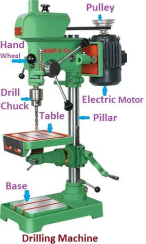
3) Swivel Table:
The table is the place where the workpiece is being mounted. The table is attached to the column and it can be rotated around the column and can have an upward and downward moment. A table can be adjusted at any angle as per the requirement.The worktable is generally made of cast iron and it is mounted on the column. T-slots are provided at the top surface of the table may be in some table there is a vice which also helps to hold the job.
The table can move up and down as also right or left according to the job and tool arrangement. The up and down motion of the table can be given by hand as well as by some electrical mechanism. We use a rack and pinion mechanism for a vertical moment of the table.
The shape of the table can be rectangular or also circular.
4) Motor:
The motor is present at the top of the column. Inside motor shaft is there which is connected to a stepped pulley so that we can increase or decrease the speed of the rotation of the motor.
5) Stepped pulley:
Two steeped pulleys are present on either side of the column at the top. Out of these two, one pulley will be in an upward direction while the other pulley is inverted. Always both the pulleys will be there in the opposite direction. The basic function of the stepped pulley is to control the speed of the rotation of the motor.
6) Spindle:
Spindle arrangement is present at top of the column opposite to the arrangement of the motor. The top of the spindle is attached to one of the stepped pulleys. The bottom of the spindle is connected to the chuck.
7) Chuck:
Chuck is present at the bottom of the spindle. The basic function of the chuck is to hold the cutting tool firmly.
8) Drill bit:
A drill bit is an actual cutting tool that is used to create a hole in the workpiece.
9) Hand Wheel:
The basic function of the hand wheel is to adjust the spindle position as per the requirement.
10) Feed Mechanism:
In a drill machine, we use an electric motor, V-belt, and pulley to transfer the power from the motor to the spindle. For the up and down motion of the drill head, we use hand and as well as automatic feed by an electrical motor. Here also a rack and pinion is used to convert the rotational movement from electrical motor or by hand to the straight-line movement.
Operation of Drilling Machine
The various operations that can be performed in a drilling machine are :
1. Drilling
2. Boring
3. Reaming
4. Counter Boring
5. Counter Sinking
6. Spot Facing
7. Tapping
8. Lapping
9. Grinding
10. Trepanning
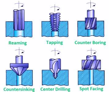
Operation of Drilling Machine
1. Drilling
- Drilling is an operation of producing a cylindrical hole by removing metal by rotating edge of cutting tool call as Drill.
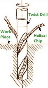
Drilling Operation
- This is one of the simplest methods of producing a hole.
- It doesn’t produce an accurate hole in a workpiece due to the vibration of the spindle and drill.
2. Boring
- The purpose of boring is to enlarge a hole by means of an adjustable cutting tool with only one cutting edge.
- It machine the internal surface of a hole already produced in casting.
- To correct out of roundness of the hole.
- To address the area of the gap as the drilling apparatus follows an autonomous way as for the gap.
3. Reaming
- It is a precise method for estimating and completing an opening which has been recently bored.
- The tool uses for reaming is known as the reamer which has multiple cutting edges.
- It can’t originate a hole.
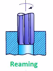
- It basically follows the way which has been recently bored and expels an extremely limited quantity of metal.
- The material removes through this process is around 0.375 mm and for accurate work this should not exceed 0.125 mm.
4. Counter Boring
- This is an operation of enlarging the end of a hole cylindrically.
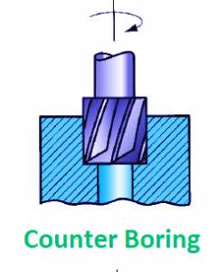
- The enlarged hole forms a square shoulder with the first gap.
- The cutting speed for this operation is 25 % less than that of drilling.
5. Counter Sinking
- It is an activity of making a cone – shaped enlargement of the end of a hole to provide a recess for a flat head screw or countersunk rivet fitted into the hole.
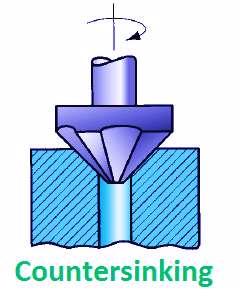
- The standard countersinks have 60°, 82° or 90° included angle and the cutting edges of the tool are formed at the conical surface.
6. Spot Facing
- This is an operation of smoothing and squaring the surface around a hole for the seat for a nut or the head of a screw.
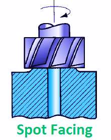
- A counter bore or an extraordinary spot confronting apparatus might be utilized for this reason.
7. Tapping
- This is an operation of cutting internal threads by means of cutting tool called a tap.
- A tap might be considered as a jolt with precise strings cut on it.
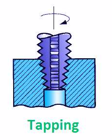
- The threads act as cutting edges which are solidified and ground.
- It removes metal and cuts internal threads which will fit into outer threads of the same size.
8. Lapping
- This is an operation of sizing and finishing a small diameter hole already hardened by removing a very small amount of material by using a lap.
- The lap fits in the hole and moves up and down while it revolves.
9. Grinding
- It is an operation to finish a hardened hole.
- The grinding wheel is made to rotate with the shaft and is exhausted and down.
- The accuracy in grinding operation is quite high about ± 0.1125 mm.
10. Trepanning
- This is an operation of producing a hole by removing metal along the circumference of a hollow cutting tool.
- It performs for producing large holes.

- The tool resembles a hollow tube having cutting edges at one end and a strong shank at the other to fit into the drill spindle.
- This is one of the effective strategies for delivering a hole.