Unit IV
Thermodynamics
Thermodynamics is the science of energy transfer and its effects on the physical properties of substance.
It deals with the transfer of energy of all kind from one form to another. It is based on first and second law of thermodynamics.
The name thermodynamics derives from Greek words thermo and dynamics meaning heat and mechanical power respectively.
Thermodynamics has wide range of applications. It is useful in the design of energy conversion devices such as internal combustion engine, steam and gas turbine, design of refrigeration and air conditioning equipment like refrigerators, air conditioners, water coolers and ice plants.
i) Thermodynamics system
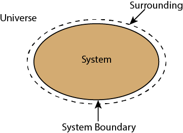
Whenever a change is to be analysed it is essential to specify the region in which the change take place. This is done by drawing a boundary aroundthe region. Boundary may be real or imaginary.
Everything within the boundary is called the system. The region outside the boundary is called surroundings
There are three types of Thermodynamics systems:
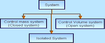
1 – Open system(control volume system): If mass and energy both cross the boundary of a system it is called open system .in open system both mass and energy can transfer across the boundaries and the mass within the system may not be constant. Most of the engineering devices are open systems involving flow of fluids through them.
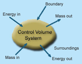
Example of open system
- Boiler – In boiler water convert from liquid to vapor phase. So, mass and energy both transfer the boundary.
- Hydraulic turbine wheel – In this device potential energy of water convert into mechanical works. Water enters the wheel from head race side and leaves it to the tail race from the other end, and as such mass cross the system boundary.
- Motor-car engine – The engine sucks charge which is mixture of air and petrol and finally exhausts the gases to the surrounding atmosphere.
2 – Closed system (control mass system): If the mass within the boundary of the system does not change, it is called closed system. A closed system does not allow any mass transfer across the boundary but allow transfer of energy across the boundary.
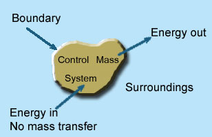
Example of closed system
- Piston cylinder assembly –the gas can reject or receive heat, expand or contract but no mass cross the boundary of system.
- Ignition system – electric energy cross, the boundary to cause a spark between electrodes an initiate combustion there is heat transfer but not mass across the system.
Pressure cooker, refrigerator, ice cream freezer etc. are the example of closed system.
3 - Isolated system: Neither mass nor energy cross the boundary of a system .it is called an isolated system. In this no mass and energy cross the system
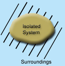
Example of isolated system
- Universe can be considered as an isolated system
- Fluid enclosed in a perfectly insulated closed vessel (thermos flask)
Ii) Properties:
There are mainly two types of thermodynamics properties:
Intensive property: If the property is independent of mass of the system is called an intensive property.
Example - Pressure, temperature,density, velocity, height, viscosity is the example of intensive property.
Extensive property: If the property is proportional to the mass of the system it is called an extensive property.
Example: volume, surface area, potential energy, kinetic energy, internal energy, electric charge.
Iii) State:
The application of thermodynamic principles begins by defining a system that is in some sense distinct from its surroundings. For example, the system could be a sample of gas inside a cylinder with a movable piston, an entire steam engine, a marathon runner, the planet Earth, a neutron star, a black hole, or even the entire universe. In general, systems are free to exchange heat, work, and other forms of energy with their surroundings.
A system’s condition at any given time is called its thermodynamic state. For a gas in a cylinder with a movable piston, the state of the system is identified by the temperature, pressure, and volume of the gas. These properties are characteristic parameters that have definite values at each state and are independent of the way in which the system arrived at that state. In other words, any change in value of a property depends only on the initial and final states of the system, not on the path followed by the system from one state to another. Such properties are called state functions. In contrast, the work done as the piston moves and the gas expands and the heat the gas absorbs from its surroundings depend on the detailed way in which the expansion occurs.
The behaviour of a complex thermodynamic system, such as Earth’s atmosphere, can be understood by first applying the principles of states and properties to its component part in this case, water, water vapour, and the various gases making up the atmosphere. By isolating samples of material whose states and properties can be controlled and manipulated, properties and their interrelations can be studied as the system changes from state to state.
Iv) Process:
Thermodynamics process represents a transition in which a system changes from one state to another. When the path is completely specified then the change of state is called a process. A Process is defined as the transformation of the system from one fixed state to another fixed state.Whenany one of the properties changes, the working substance or system is said to have undergone a process.
Some of the processes are identified by special names as given below:
- Isobaric process (constant pressure process)
- Isochoric process (constant volume process)
- Isothermal process (constant temperature process)
- Isentropic process (constant entropy process)
- Adiabatic process(perfectly insulated process)
Zeroth Law of thermodynamics
If two systems are each in thermal equilibrium with the third system then the two system are in thermal equilibrium which each other.
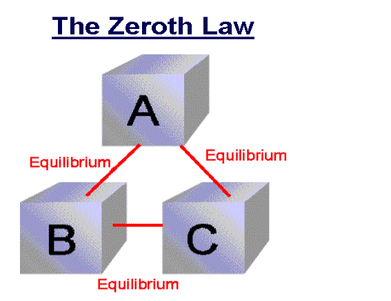
When a body A is in thermal equilibrium with a body B, and also separately with a body C, then B and C will thermal equilibrium with each other. This is known as the Zeroth law of thermodynamics.
First law of Thermodynamics
Sometimes our body start to sweat and feel warm when we are in a room full of people and the sweating becomes excessive if the room size is small. This happens because our body is trying to cool off hence heat transfers from our body in the form of ‘sweat’. This entails the first law of thermodynamics.
The first law of thermodynamics states that the total energy of an isolated system is constant. Energy can be transformed from one form to another, but can neither be created nor destroyed.
According to this law, some of the heat given to system is used to change the internal energy while the rest in doing work by the system. Mathematically,
ΔQ=ΔU+ΔW
Where,
ΔQ = Heat supplied to the system
ΔW= Work done by the system.
ΔU = Change in the internal energy of the system.
If Q is positive, then there is a net heat transfer into the system, if W is positive, then there is work done by the system. So positive Q adds energy to the system and positive W takes energy from the system.
It can also be represented as ΔU=ΔQ−W
We can say that internal energy tends to increase when heat is given to the system and vice versa.
Limitations of First Law of Thermodynamics
- The limitation of the first law of thermodynamics is that it does not say anything about the direction of flow of heat.
- It does not say anything whether the process is a spontaneous process or not.
- The reverse process is not possible. In actual practice, the heat doesn’t convert completely into work. If it would have been possible to convert the whole heat into work, then we could drive ships across the ocean by extracting heat from the water of the ocean.
Second law of thermodynamics
Kelvin-Planck statement
It is impossible to convert all the heat extracted from a hot body into work. In the heat engine, the working substance takes heat from the hot body, converts a part of it into work and gives the rest to the cold body. There is no engine that can convert all the heat taken from the source into work, without giving any heat into the sink. This means that for obtaining continuous work, a sink is necessary.
Clausius statement
It is not at all possible to transfer heat from a cold body to a hot body without the expenditure of work by an external energy source or its states that the heat energy cannot transfer from a body at a lower temperature to a body at a higher temperature without the addition of energy.
For example - There is a refrigerator that transfers an amount of heat from a cold body to a hot body without having any supply of external energy. So, this is the violation of Clausius statement. Now suppose an engine working between the same hot and cold bodies takes in heat from hot body converts a part W into work and gives the remaining heat to the cold body. The engine alone does not violate the second law of thermodynamics. But if the engine and refrigerator combine together, they form a device that takes up all the heat from the hot body and converts all into work without giving up any amount to the cold body. It, violets the Kelvin-Planck statement. So, we say that the two statements of the second law of thermodynamics are equal in all respects
A process is a change in the state of a gas as a result of flow of energy. During this flow a change takes place in properties of the substance such as pressure, volume, temperature and also the energy quantities such as internal energy, heat and work.
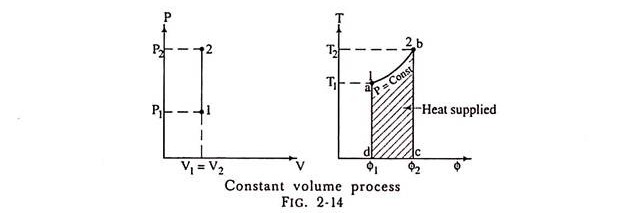
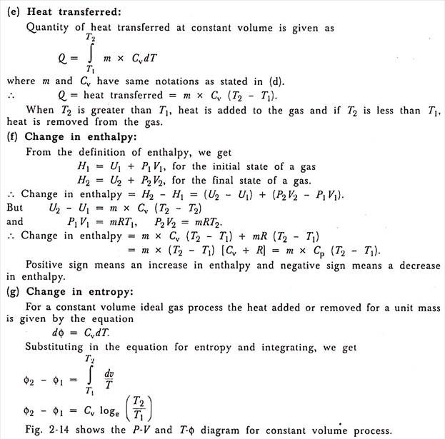
Constant volume:
Constant Volume Process:
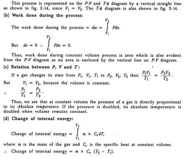
(a) Representation on P-V and T-ɸ diagram:
2. Constant Pressure Process:

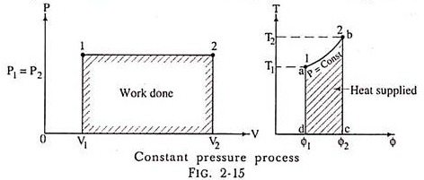
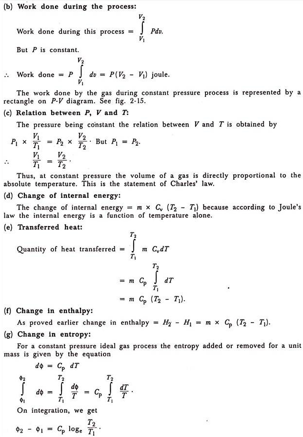
Isentropic Process:(constant entropy)
In this process the gas neither receives nor gives out heat. We may imagine that the gas is contained in a cylinder made of ideal non-conducting material. The gas can then be expanded or compressed but no heat can either be given to or taken from the gas.
Students very frequently misunderstand the meaning of isentropic (adiabatic) expansion or compression. During expansion, the temperature falls and there is loss of internal energy but no heat is lost in the form of heat from the system. Fig. 2-17 shows a frictionless totally isolated cylinder and piston mechanism of heat engine.
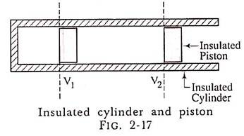
In the isentropic process, the gas does not loose, any heat to the surrounding and is completely isolated system by use of ideal insulating materials. If the friction is present in the mechanism then such a process is called Adiabatic process and the isentropic process is a frictionless adiabatic process.
(a) Law of Isentropic Process:
By first law of thermodynamics as applied to non-flow process,
Heat supplied = change in internal energy + work done.
Let us consider unit mass of a gas.
Let dQ denote a small quantity of heat taken in by unit mass of a perfect gas and dT and dv being the resulting small increments of temperature and volume respectively;
Then according to first law of thermodynamics,
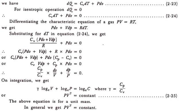
Thus, we get in equation which is followed by a gas when it expands or compresses isentropic ally
.
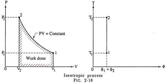
(b) Representation on P-V and T-ɸ Diagram:
The isentropic process on P-V diagram is represented as shown in fig. 2-18. The T-ɸ diagram shows the entropy remains constant.
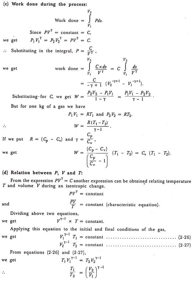
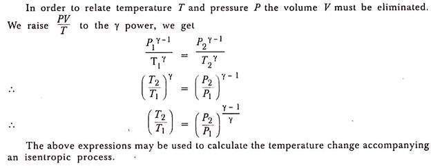
(e) Change in Internal Energy:
As usual, we get
Change in internal energy = U2 – U1 = m x Cv (T2 – T1).
Another way of determination of change in internal energy is very common in isentropic operation.
By first law of thermodynamics as applied to non-flow process,
Heat supplied = change in internal energy + work done; but heat supplied is zero
∴ Change in internal energy = – work done.
Thus, we get an important relation in an isentropic process. This relation can be stated as “Change in internal energy is numerically equal to work done”. When the work is done by the gas, it loses internal energy and it gains internal energy when the work is done on the gas.
(f) Transferred Heat:
During an isentropic operation the transferred heat is zero.
Δ Q= 0.
(g) Change in Enthalpy:
Change in enthalpy = H2 – H1 = m x Cp (T2 – T1).
(h) Change in Entropy:
The change in entropy is 0 because dQ = 0.
dɸ = ɸ2 – ɸ1 = 0.
As for frictionless isentropic process the heat added or removed will be zero, the change in entropy will also be zero. Hence, we get ɸ1= ɸ2; in other words, we say that during frictionless isentropic process the entropy remains constant and its representation on a temperature entropy diagram will be a vertical straight-line ab as shown in fig.
Constant enthalpy:
In thermodynamics process constant enthalpy means that enthalpy does not change in all process. Best understand the concept of constant enthalpy wo should understand the throttling process.
Throttling Process:
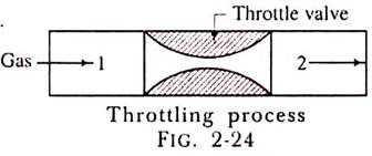
The throttling process is an expansion process in which the pressure reduces after expansion and the velocity is negligible. A throttling expansion occurs when a gas or a vapour is expanded through an aperture of minute dimensions such as a throat or a slightly opened valve.
During the throttling process the expanding fluid is forced through the aperture by its pressure but the hole is so narrow that the frictional resistance between the fluid and the wall reduces the fluid velocity to a negligible amount; as a result, the fluid escapes with a small amount of kinetic energy.
Due to friction kinetic energy reappears as heat and the gas is raised to its initial temperature. During a throttling process no heat is supplied or rejected, no external work is done and in the case of a perfect gas there is no alteration in temperature.
When a fluid expands through a throttle valve or a constricted orifice, the enthalpy before the throttling valve is equal to the enthalpy after throttling. This does not mean, however, that the throttling process is constant enthalpy process. Here the properties before and after the process are defined. Fig. 2-24 shows throttling process.
H1 = H2.
In this process the enthalpy remains constant. The enthalpy at condition 1 is equal to enthalpy at condition 2.
Steam Engineering
A steam boiler or steam generator is a closed vessel in which water is heated, vaporized and converted into steam at a pressure higher than atmospheric pressure. Boiler is a closed vessel in which heat produced by combustion of fuel is transferred to water for its conversion in to steam at the desired temperature and pressure. According to IBR a boiler is closed pressure vessel with capacity exceeding 25.75 Litres used for IBR a boiler is closed pressure vessel with capacity exceeding 25.75 Litres used for generating steam under pressure it includes all the mountings fitted to such vessels which remains wholly or partly under pressure when steam is shut off.
Working Principle of a Boiler
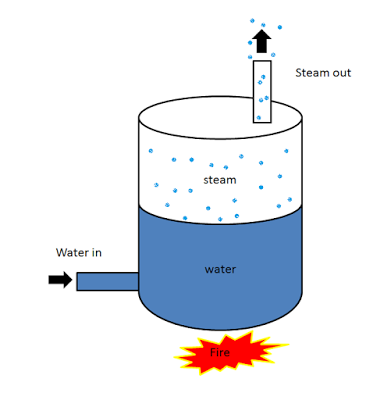
The boiler works on the same principle as the water is heated in a closed vessel and due to heating, the water changes into steam. This steam possesses high-pressure kinetic energy. The boiler contains water. The water is heated to its boiling temperature by the use of heat from the furnace. Due to the heating of water, it gets converted into high-pressure steam. The steam generated is passed through the steam turbines. As the high-pressure steam strikes the turbine, it rotates the turbine. A generator is attached to the turbine and the generator also starts to rotate with the turbine and produces electricity.
Classifications or Types of Boiler:
There is large number of boiler designs, but they may be classified according to the following ways:
1) According to the circulation of gases:
- Fire-tube boiler
- Water-tube boiler
Fire Tube Boiler:
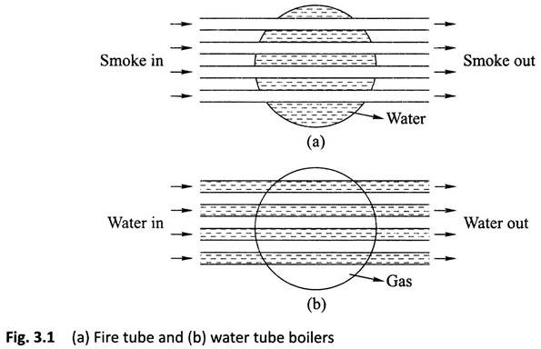
As it indicated from the name, the fire tube boiler consists of numbers of tubes through which hot gasses are passed. These hot gas tubes are immersed into water, in a closed vessel. Actually, in fire tube boiler one closed vessel or shell contains water, through which hot tubes are passed. These fire tubes or hot gas tubes heated up the water and convert the water into steam and the steam remains in same vessel. As the water and steam both are in same vessel a fire tube boiler cannot produce steam at very high pressure. Generally, it can produce maximum 17.5 kg/cm2 and with a capacity of 9 Metric Ton of steam per hour.
(a) Hot gases formed after the combustion of fuel flow through tubes and water surrounds these tubes.
(b) Internally fired.
(c) Working pressure limited to 20 bars.
(d) Steam generation rate is lower.
(e) For a given power, it occupies large floor area.
(f) Not suitable for large power plants.
(g) It carries lot of risk on less working pressure.
(h) Different parts cannot be separated easily, hence it becomes difficult to transport.
(i) Water treatment is not necessary.
(j) Parts are not so accessible for cleaning and inspection.
Fire tube boilers are classified as follows.
l. External furnace:
(i) Horizontal return tubular
(ii) Short fire box
(iii) Compact.
2. Internal furnace:
(i) Horizontal tubular
(a) Short firebox (b) Locomotive (c) Compact (d) Scotch.
(ii) Vertical tubular.
(a) Straight vertical shell, vertical tube
(b) Cochran (vertical shell) horizontal tube.
Advantages of Fire Tube Boiler
- It is quite compact in construction.
- Fluctuation of steam demand can be met easily.
- It is also quite cheap.
Disadvantages of Fire Tube Boiler
- As the water required for operation of the boiler is quite large, it requires long time for rising steam at desired pressure.
- As the water and steam are in same vessel the very high pressure of steam is not possible.
- The steam received from fire tube boiler is not very dry.
Water Tube Boiler:
A water tube boiler is such kind of boiler where the water is heated inside tubes and the hot gasses surround them.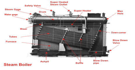
This is the basic definition of water tube boiler. Actually, this boiler is just opposite of fire tube boiler where hot gasses are passed through tubes which are surrounded by water.
(a) Water flows inside the tubes and gas surrounds these tubes.
(b) Externally fired.
(c) Working pressure may be as high as 150 bars.
(d) Steam generation rate is higher.
(e) For a given power, it occupies lesser floor area.
(f) Suitable for large power plants
(g) Less risk on explosion due to high working pressure.
(h) Each and every part can be separated easily, so transportation is easier.
(i) In this boiler, water treatment is necessary.
(j) Parts are easily accessible for inspection.
There are many types of water tube boilers, such as
- Horizontal Straight Tube Boiler.
- Bent Tube Boiler.
- Cyclone Fired Boiler.
Horizontal Straight Tube Boiler again can be sub-divided into two different types,
- Longitudinal Drum Water Tube Boiler.
- Cross Drum Water Tube Boiler.
Bent Tube Boiler also can be sub divided into four different types,
- Two Drum Bent Tube Boiler.
- Three Drum Bent Tube Boiler.
- Low Head Three Drum Bent Tube Boiler.
- Four Drum Bent Tube Boiler.
Advantages of Water Tube Boiler
There are many advantages of water tube boiler due to which these types of boiler are essentially used in large thermal power plant.
- Larger heating surface can be achieved by using more numbers of water tubes.
- Due to convectional flow, movement of water is much faster than that of fire tube boiler, hence rate of heat transfer is high which results into higher efficiency.
- Very high pressure in order of 140 kg/cm2 can be obtained smoothly.
Disadvantages of Water Tube Boiler
- The main disadvantage of water tube boiler is that it is not compact in construction.
- Its cost is not cheap.
- Size is a difficulty for transportation and construction.
2) According to Circulation of water:
- Free circulation
- Forced circulation
Free circulation:
In any water heating vessel heat is transmitted from one place to another not by condition but by convection because water is a bad conductor of heat.Let vessel containing water be heated at its bottom, as the water in the bottom portion is heated therefore its density becomes reduced in comparison to the density of water in the upper portion of the vessel, as a result, the less dense water at the bottom portion of the vessel rise up and comparatively more dense and cold water at the upper portion of the vessel comes down to take its place and thus a convection current is set up in the water until temperature off all water becomes the same.
The method of circulation of water described above is known as free circulation.
In boilers like Lancashire, Babcock, and Wilcox, etc. free circulation of water takes place.
- Advantages of free circulation:
The advantages of free circulation are:
- Free circulation of water helps to maintain a uniform temperature true everywhere within the boiler so that unequal expansion of various parts of the boiler is prevented.
- Free circulation of water facilities the escape of steam from the heating surface as soon as it formed. If steam does not escape quickly after its formation the boilerplates do not remain constantly in touch with water and as a result, these plates may be overheated.
Forced Circulation:
In forced circulation, pumps are used to maintains the continuous flow of water in the boiler. In such a case, the circulation of water takes place due to pressure created by the pump.
The forced circulation system is adopted in more high pressure, high capacity boilers of all of which are water tube type boiler
- Advantages of forced circulation:
The advantages of forced circulation are:
- The rate of heat transfer from the flue gases to the water higher.
- Tubes having comparatively smaller diameters can be used. This reduces the overall weight of the boiler.
- The number of boiler drums required may be reduced.
- Less scale formation in the boilers is required.
- Steam can be quickly generated.
- The fluctuation of load can be easily met without taking the help of any complicated controlled device.
- Chance of overheating of the boilerplates in minimum.
- Weight per unit mass of steam generated is less.
3) According to the number of tubes used:
According to the number of tubes, Boilers may be classified as:
- Single tube boiler
- Multi-tube boiler
Single tube boiler:
The boiler having only one fire tube or water tube is called single tube boiler.
Example: Cornish boiler
Multi tube boiler
The boiler having two or more fire or water tubes for the circulation of hot gases or water are called multi tube boiler.
Example: Lancashire boiler, Locomotive boiler, Cochran boiler, Babcock and Wilcox boiler etc.
4) According to the nature of use:
According to nature use, boilers are classified as
- Stationary boilers
- Locomotive boilers
- Marine boilers.
Stationary boilers:
For the generation of thermal power and for process work (in chemical, sager and textile industries) boilers used are called stationary boiler.
Locomotive boilers:
Boilers used in locomotive steam engines are called locomotive boilers.
Marine boilers:
Boilers used in steamships are called marine boilers.
5) According to the nature of the fuels used:
According to the nature of the fuel used boiler may be:
- Fuel-fired
- Gas fired
- Liquid fuel fired
- Electrically fired
- Nuclear fired
NOTE: Babcock and Wilcox boilers use solid or gaseous fuel.
Volex boilers use oil fuel.
6) According to the pressure of the boiler:
- High-pressure boiler
- Medium-pressure boiler
- Low-pressure boiler
High-pressure boiler:
The pressure of the boiler above 80 bar.
Medium-pressure boiler:
It has a working pressure of steam from 20 bar to 80 bar. It is used for power generation or process heating.
Low-pressure boiler:
This type of boiler produces steam at 15-20 bar pressure. This is used for process heating.
7) According to the position of the axis of the boiler shell:
According to the position of the axis of the boiler shell, boilers are classified as:
- Vertical boiler
- Horizontal boiler
Vertical boiler:
If the boiler axis is vertical, it is called a vertical boiler. For example, Cochran boiler
Horizontal boiler:
If the boiler axis is horizontal, it is called a horizontal boiler.
For example, Lancashire boiler.
8)Stationary boiler and Portable boiler
a) Stationary boilers: The boilers which cannot be transported easily from one place to another are called stationary boilers.
Example: Lancashire boiler, Babcock and Wilcox boiler
(b) Portable boiler: The boilers which can be easily transported (moved) from one place to another are called portable boilers.
Example: Locomotive boiler.
9) Externally tired and internally tired boilers
(a) Externally fired boiler: - In the boiler if the fire is outside the shell, that boiler is known as externally fired boiler. Example: Babcock & Wilcox boiler
(b) Internally fire boiler- In the boiler in which the furnace is located inside the boiler shell it is known as internally fired boiler. Example: Cochran boiler, Lancashire boiler etc.
The boiler mountings are fittings which are mounted on the boiler for its proper functioning. Mountings are water level indicator, safety valve, pressure gauge, etc. It may be noted that a boiler cannot function safely without the mountings
Following are the important boiler mountings:
- Water level indicator
- Pressure gauge
- Safety valve
- Stop valve
- Blow off
- Feed check valve
- Fusible plug
1) Water Level Indicator
It is a main fitting in the boiler, Water level indicator indicates the water level inside the boiler. It is a safety device upon which safe working of the boiler depends.
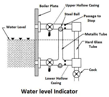
Working Principle
Water-tube indicator the water consists of a vertical hard glass tube G which is fitted with two gunmetal tubes A and B. The tubes A connects the steam space of the boiler with the glass tube and the tube B connects the water space of the boiler with the glass tube.
The tube A is provided with a valve ‘S’, called a steam valve, and tube B is fitted with another valve ‘W’, called a water valve. In addition to these valves, a third valveD, called drain valve, is fitted to the water level indicator through which water together with condensed steam from the gunmetal tube A is drained from time to time.
2) Pressure Gauge
Pressure gauges are used to measure the pressure of steam inside a steam boiler. The pressure gauge is fixed in front of a steam boiler.
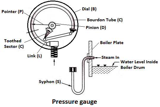
Working Principle
The pressure gauge shown in fig is bourdon pressure gauge. It consists of a circular spring tube A. One end of the bourdon tube is closed and connected to a link L and the other end is squared to a Hollow block B. The link L connects the closed end of the tube to the toothed sector C which is hinged at O. The toothed sector gears with pinion D which carries a pointer P. The pointer moves on a dial graduated in pressure units.
3) Safety valves
These are the devices attached in the steam boiler for preventing explosions due to excessive internal pressure of steam.
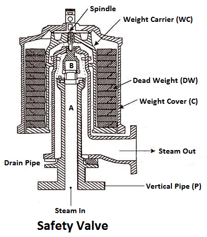
The safety valve is an instrument which prevents the boiler pressure from rising above its normal working pressure by automatically opening when the boiler pressure exceeds the normal working pressure, Thus, allowing excess steam to escape into the atmosphere until the pressure comes down to its normal valve. Thus, a safety valve ensures safety to a boiler from being damaged due to excessive steam pressure.
The safety valves commonly used are:
- Deadweight safety valve,
- Lever safety valve,
- Spring-loaded safety valve,
4) Steam stop valve
The function of a stop valve is to control the flow of the steam from within the boiler and to stop it completely when required. A stop valve or junction valve is used to regulate the flow of steam from the boiler.
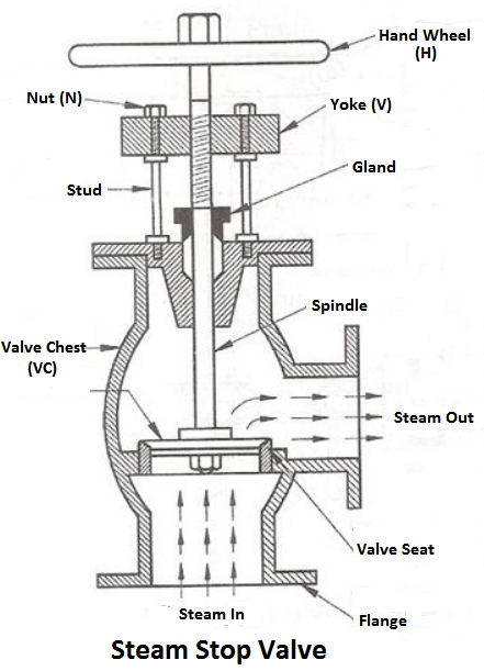
The valves mounted on the boilers, which change the direction of flow of steam by 90° are called junction valves, while valves fitted in pipelines which allowing the steam in the same direction are called stop valve.
5) Blow-off Valve
The function of a blow-off valve is to remove periodically the sediments deposited at the bottom of the boiler while the boiler is in operation and to empty the boiler while it is being cleaned or inspected.
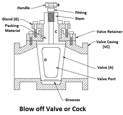
When the blow-off valve is opened the water, which is under the pressure of steam, rushes out with tremendous velocity thus carrying out the sediments along with it.
6) Feed Check Valve
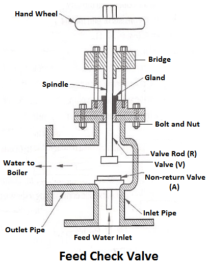
When the level of water in the boiler falls, it is brought back to the specified level by supplying the additional water called feed water. The pressure inside the boiler will be high therefore the pressure of the feed water has to be raised by a pump before it is fed into the boiler. The feed water under high pressure is fed into the boiler through the feed check valve.
The function of a feed check valve is to control the flow of water from the feed pump to the boiler and to prevent the backflow of water from the boiler to the pump when the pump pressure is less than the pressure or when the feed pump ceases to work. Evidently feed check valve is placed at the boiler end of the delivery pipe of the feed pump.
7) Fusible Plug
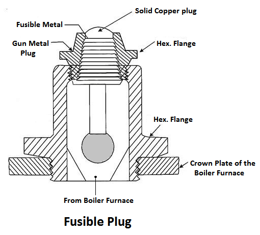
The plug is made up of tin or leads alloy, which has a low melting point. The function of the fusible plug is to put-off the fire in the furnace of the boiler when the water level falls below an unsafe level and thus avoids the explosion, which may take place due to overheating of the tubes and the shell. It is fitted over the crown of the furnace or the combustion chamber.
Boiler Accessories
The boiler accessories are required to improve the efficiency of the steam power plant and to enable for the proper working of the boiler. The boiler accessories are the devices, which form an integral part of a boiler but are not mounted on it. They include superheaters, economiser, feed pump etc. It may be noted the accessories help in controlling and running the boiler efficiently.The boiler accessories aren’t mounted directly on the boiler.
The essential boiler accessories are:
- Economiser
- Air pre-heater
- Superheaters
- Feed pump
- Steam Separator
- Steam trap
1) Economiser
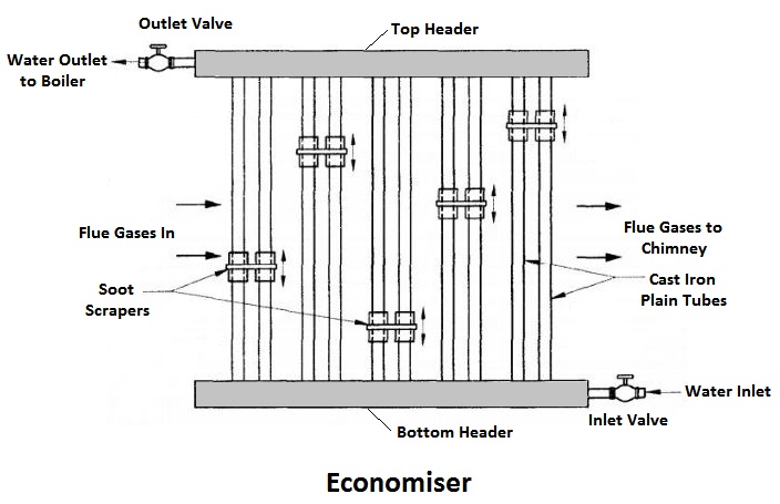
The combustion gases coming out of the boiler contain a large quantity of heat. Therefore, the maximum amount of heat from the gases should be recovered before it escapes to the chimney.
In the economiser, heating the feed water does the recovery of heat in the flue gases. The economiser is placed in the path of the gases. They improve the overall efficiency of the boiler by reducing fuel consumption.
2) Air Pre-heater
The air preheater is an accessory that recovers the heat in the exhaust gas by heating the air supplied to the furnace of the boiler. Supplying preheated air into the furnace produces a high furnace temperature and accelerates the combustion of the fuel. Thus, the thermal efficiency of the plant will be increased.
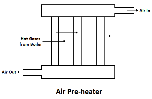
The advantages of air pre-heater are,
- Increase in the steam generation rate.
- Better combustion with less soot, smoke and ash, and
- Low-grade fuels can be used.
3) Superheaters
The superheaters are used in boilers to increase the temperature of the steam about the saturation temperature.
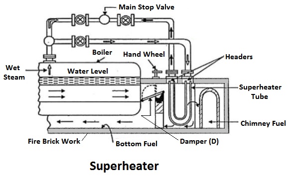
The dry saturated steam generated in the boiler is passed through a set of tubes placed in the path of the flue gases, in which it will be heated further by the hot gas to increase its temperature about the saturation temperature.
4) Feed Pump
A feed pump is a boiler accessory required to force the feed water at high pressure into the boiler. Commonly used pumps are,
- Reciprocating pumps
- Rotary pumps
The reciprocating pumps are driven directly by coupling them to the steam engine. The rotary pumps are driven by the steam turbines or by electric motors.
.
Boiler Performance:
It may be expressed in terms of quantity of steam produced per kg of coal. Alternatively, the efficiency of the boiler may be taken as a measure of its performance.
The comparison between any two boilers is possible only when they use the same fuel, have the same feed water temperature and working pressure. Actual conditions vary considerably in this respect and it is necessary to adopt standard reference feed temperature and working pressure. The feed temperature adopted is 100°C and the working pressure 1.01325 bar the pressure of the atmosphere at sea level.
Under these conditions, evaporation of 1 kg of water requires the latent heat of 1 kg of steam, the value of which is 2256.9 kJ/kg. This quantity is known as ‘Standard Evaporation Unit’.
Efficiency of Boiler:
The efficiency is defined as ratio of heat output to the heat input in percentage.
Some controversy exists at present among engineers as to whether the boiler efficiency should be expressed in terms of the gross calorific value of the fuel as fired, or its net calorific value, or “by difference”.
The gross calorific value is, of course, the total heating value of the fuel per unit of weight or volume, including the heat of oxidation of the hydrogen in the fuel to water (steam) plus the latent heat of the total moisture in the fuel. On the other hand, the net calorific value of the same fuel is the total heating value of the combustible elements only, and excludes the heat of formation of water from the hydrogen and the evaporation of the moisture in the fuel to steam.
Some engineers prefer to quote their boiler efficiencies “by difference”, which means that the figure is obtained by subtracting all the accounted heat losses from a hundred. The boiler efficiency expressed in this way includes all the losses which cannot be determined; thus, it gives an exaggerated value. It also assumes that all the measured losses have been correctly determined.
The percentage of total heat exported by outlet steam in the total heat supplied by the fuel (coal) is called steam boiler efficiency.
Steam boiler efficiency (%) = (heat exported by outlet steam/ heat supplied by the fuel) x 100
It includes with thermal efficiency, combustion efficiency and fuel to steam efficiency. Steam boiler efficiency depends upon the size of boiler used. A typical efficiency of steam boiler is 80% to 88%. Actually, there are some losses occur like incomplete combustion, radiating loss occurs from steam boiler surrounding wall, defective combustion gas etc. Hence, efficiency of steam boiler gives this result.
Boiler efficiency is a combined result of efficiencies of different components of a boiler. A boiler has many sub systems whose efficiency affects the overall boiler efficiency. Couple of efficiencies which finally decide the boiler efficiency are-
- Combustion efficiency
- Thermal efficiency
Apart from these efficiencies, there are some other losses which also play a role while deciding the boiler efficiency and hence need to be considered while calculating the boiler efficiency.
Combustion Efficiency
The combustion efficiency of a boiler is the indication of burner’s ability to burn fuel. The two parameters which determine the burner efficiency are unburnt fuel quantities in exhaust and excess oxygen levels in the exhaust. As the amount of excess air is increased, the quantity of unburnt fuel in the exhaust decreases. This results in lowering the unburnt fuel losses but elevating the enthalpy losses. Hence, it is quite important to maintain a balance between enthalpy losses and un burnt losses. Combustion efficiency also varies with the fuel being burnt. Combustion efficiency is higher for liquid and gaseous fuels than for solid fuels.
Thermal Efficiency
The thermal efficiency of a boiler specifies the effectiveness of the heat exchanger of the boiler which actually transfers the heat energy from fireside to water side. Thermal efficiency is badly affected by scale formation/soot formation on the boiler tubes.
Direct and Indirect Boiler Efficiency
The overall boiler efficiency depends on many more parameters apart from combustion and thermal efficiencies. These other parameters include ON-OFF losses, radiation losses, and convection losses, blow down losses etc. In actual practice, two methods are commonly used to find out boiler efficiency, namely direct method and indirect method of efficiency calculation.
Direct efficiency
This method calculates boiler efficiency by using the basic efficiency formula-
η= (Energy output)/(Energy input) X 100
In order to calculate boiler efficiency by this method, we divide the total energy output of a boiler by total energy input given to the boiler, multiplied by hundred.
Calculation of direct efficiency-
E= [Q (H-h)/q*GCV]*100
Where,
Q= Quantity of steam generated (kg/hr)
H= Enthalpy of steam (Kcal/kg)
h= Enthalpy of water (kcal/kg)
GCV= Gross calorific value of the fuel.
Indirect Efficiency
The indirect efficiency of a boiler is calculated by finding out the individual losses taking place in a boiler and then subtracting the sum from 100%. This method involves finding out the magnitudes of all the measurable losses taking place in a boiler by separate measurements. All these losses are added and subtracted from 100% to find out the final efficiency. Blow down valve is kept closed during the procedure. This method should be implemented as per the norms provided in BS845 standards. The losses calculated include stack losses, radiation losses, blow down losses etc.
Comparison of direct and indirect efficiency-
Both the methods of finding out boiler efficiency mentioned above have some advantages and some disadvantages associated with them. The greatest advantage of indirect method is that it also speaks about the sources of losses. By finding out indirect efficiency, one can come to know where the losses are increased and can be reduced. On the other hand, direct efficiency values are closer to reality as compared to indirect efficiency on account of uncovered losses such as radiation losses, ON-OFF losses etc. But direct efficiency can only tell us about the magnitude of overall loss. No information about individual losses and their magnitudes is conveyed from direct efficiency calculation. There always exists some difference in the values of direct and indirect efficiencies. Indirect efficiency is measured at a particular time whereas direct efficiency is measured over a period of time and hence, losses on account of fluctuating loads, boiler on-off etc. is also taken into consideration.
Draught may be defined as the small pressure difference which causes a flow of gas to take place. In case of a boiler the function of the draught is to force air to the fire and through a boiler furnace and flue, and to discharge the products of combustion to atmosphere via stack or chimney.
Proper combustion in a boiler furnace can only occur when sufficient quantity of air is supplied to the burning fuel. If the supply of air is insufficient, then the combustion will be sluggish and insufficient even with superfine furnace construction and the most skilful stoking.
Classification of Draught:
The classification of draught is as below:
(1) Natural
(2) Artificial.
1) Natural draught
In case of a natural draught if we consider a condition when fire is not lighted, the pressure at the grate level surface is the same at all points on the surface i.e., at the chimney base as well as on the grate and we assume its value to be P1.
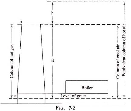
The pressure at all points at horizontal surface ‘b’ passing from the top of the chimney in fig. 7-2 is also the same and we take its value to be P2. The value of P2 is less than P1 because the surface ‘b’ is higher than the surface ‘a’ by H, the height of the chimney. When the fire is lighted up on the grate, the hot gases will fill up the chimney as well as flue gas passages.
Now, though, the pressure at the chimney top is P2 the pressure at the grate level below the grate is P1 but at the base of the chimney it will be P2 + pressure due to the hot gas column of height H. This pressure will be less than P1 because P1 = P2 + the pressure due to the cold air column of height H.
Now, a cold air column of the same height is heavier than a hot gas column and so the pressure difference at the base of the chimney corresponding to grate pressure is the pressure difference in weight of the column of height H of cold air and that of hot gases, and this is known as total static draught or theoretical maximum static draught.
Thus, total static draught is the total pressure difference which results owing to the difference in the weights of the column of the hot flue gas inside the chimney and a column of the outside air of the same area and height.
2) Artificial Draught:
In present day boiler installations, the total static draught required varies from 25 to 350 mm of water column because loss in draught takes place in boiler tubes, super heater elements, baffles, economizer and air pre-heater. Besides, resistance to air flow is also offered by combustion equipment.
It will not be practical to build a stack high enough to produce a draught of such a large magnitude. Natural draught is dependent on climatic conditions and is less when the outside air temperature is higher and thus it is necessary to obtain a draught which is independent of weather conditions.
To meet the desired pressure requirement which is independent of climatic conditions, an artificial draught is created. It may be a mechanical draught or a steam jet draught is used while for central power stations and many other boiler installations a mechanical draught is preferred.
I. Steam Jet Draught:
Simple and easy method of producing artificial draught is the steam jet draught. It may also be of the forced draught type or induced draught type.
When the jet of steam is directed into the smoke box or in chimney it induces the draught and the air is drawn through ashpit, furl bed and boiler flue tubes. When the jet is installed in the ashpit, the draught becomes of the forced type and air is forced through the fuel bed, boiler flue tubes and the chimney.
In case of locomotives, the exhaust from non-condensing steam engine is directed into the smoke box. With this arrangement the draught is automatically adjusted to suit the requirements of the boiler.
The steam jet draught system requires very little attention and is economical when cheap and plenty of low-grade fuels are employed. It has one disadvantage that it cannot be started until steam pressure is available. Steam passing into the furnace will carry away heat in the same manner as moisture in the fuel.
II. Mechanical Draught:
The mechanical draught is the draught created by use of mechanical equipment to create an artificial draught.
The Advantages of Mechanical Draught are:
(i) Increase in Evaporative Power of a Boiler:
By installing the mechanical draught system, the quantity of fuel burnt, per square metre of grate area, is increased. Generally, with natural draught system the average fuel consumption per square metre of grate area varies from 80 to 170 kg depending upon the height of the chimney.
With mechanical draught, any type of mechanical stoker can be adopted and any desired rate of fuel consumption up to 200 kg/m2 of grate area can be maintained in any type of boiler. With tubular boilers the fuel can be burnt at a better rate. As the combustion rate of fuel has increased, the steam raising capacity of the plant is increased.
(ii) Capability of Consuming Low-Grade Fuel:
With mechanical draught installation many kinds of low-grade fuels can be used for steam raising purposes.
(iii) Easy Control of Combustion and Evaporation:
Greater economy in working can be obtained because complete combustion is possible with less excess air. The rate of air supply can be regulated to suit the irate of fuel consumption which in turn regulates the evaporation of steam.
(iv) Prevention of Smoke:
Smoke prevention depends upon the quantity of air supplied and the condition of firing. With mechanical draught and mechanical stokers’ high temperatures and efficient combustion can be obtained with less difficulty.
(v) Improved Efficiency of the Plant:
As the temperature of flue gases can be lowered with mechanical draught system heat recovery devices are incorporated in the boiler plant. By installing the economizer, the temperature of feed water entering boiler is raised, while the air pre-heater heats the combustion air. Both these devices improve the thermal efficiency of the boiler plant.
(vi) Reduction of Chimney Height:
With the mechanical draught system, the function of a chimney is only to discharge flue gases t a convenient height to suit the surroundings and comply with local by-laws.
The disadvantages of mechanical draught are:
(i) Cost of driving the fan
(ii) Upkeep of machinery
(iii) Increased wear and repairs which are expected owing to the increased duty which the boilers are called upon to perform.
When we provide continuous heat to water then at 100 temperature and 1 atm pressure, it boils and changes its phase from liquid to vapour. This vapour is known as steam.
Steam contains more energy as it has both sensible heat and latent heat of vaporization. Steam has been a popular mode of conveying energy since the industrial revolution. Steam is used for generating power and also used in process industries such as sugar, paper, fertilizer, refineries, petrochemicals, chemical, food, synthetic fibre and textiles the following characteristics of steam make it so popular and useful to the industry:
• Highest specific heat and latent heat
• Highest heat transfer coefficient
• Easy to control and distribute
• Cheap and inert
Types: Wet steam, Dry steam, Superheated steam
Wet Steam: When steam contains water particles then it is known as Wet steam
Dry Steam: When wet steam is further heated then all water particles get converted into vapour and resulted steam is called dry steam.
Superheated Steam: When dry saturated steam is heated to higher temperatures then steam obtained is in superheated state. This steam is mostly used in Power generation.
Use
(1) Power generation
(2) Heat engines (i.e. steam engines train)
Thermodynamic properties of steam:
It is necessary to understand the properties of steam so that we can make proper use of it. Equipment size can be decided, pipe systems can be perfectly designed. It also allows us to make informed decisions affecting the energy usage of the system.
The properties are:
(1) Quality of steam (Dryness fraction)
Dryness fraction in simple words denotes the mass of dry steam in given steam. Or how much steam is dry or in other words how much water vapour is present in steam. It is denoted by ‘x’.
X = M / M+m
Where M=mass of the dry steam
m=mass of water vapour
The use of dryness fraction allows us to know both the mass of dry steam and mass of water vapour.
Now, see
If x = 0.9 that means dry steam is 0.9 kg and water vapour is 0.1 kg in 1 kg of given steam.
Obviously for dry steam, x = 1
Quality is represented in percentage but meaning is same as ‘x’.
If quality of steam is 80%, then it has 80% of dry steam and 20 % water vapour by mass.
(2) Specific volume:
Gases (steam is a gas) occupy less space under higher pressure than under lower pressure. This means 1 kilogram of steam occupies different volumes, depending upon its pressure. The term specific volume refers to the volume that one kg of steam occupies at a given pressure and temperature.
Unit is m3 / kg denoted by v
(3) Enthalpy
The total heat content of a substance is called enthalpy. Actually, it has much broad definition in thermodynamics but for 1st year BME students this definition works just fine. So, total heat content by steam is termed as its enthalpy. It is denoted by ‘H’. SI unit is KJ
‘h‘ is generally used term which represents specific enthalpy, unit for which is KJ/Kg.
In steam tables you will see enthalpy written as hi, hg, hig
hiis the enthalpy of liquid that is water at boiling point that’s why subscript ‘l’ is used, point ‘D’ in h-T diagram. Similarly, hg is enthalpy of dry saturated steam, point ‘E’ in h-T diagram and hig is the latent heat, Process D to E in h-T diagram.
Types of Steam
Steam is an invisible gas created by adding heat energy to water. It is liquid water changed to its gaseous state.
Saturated steam - steam in immediate contact with the water from which it is being generated. If the pressure remains constant, any loss of heat or BTUs will result in condensation.
Superheated steam – If more heat is added to dry saturated steam at a constant pressure, increasing its temperature and specific volume, super-heated steam is produced. Heat must be lost, and temperature reduced before condensation occurs.
Flash steam - when condensate, at saturation temperature and pressure, is discharged into a region of lower pressure, it automatically adjusts to the saturated conditions at the lower pressure. In effect, some of the condensate is “re-evaporated” into steam.
Use of steam table:
The thermodynamics steam tables contain the following tables:
Saturated water and steam temperature tables: In these tables for every temperature the absolute pressure, specific volume for saturated water and saturated steam, specific enthalpy for saturated water and saturated steam and specific entropy for saturated and saturated steam are given.
Saturated water and steam pressure tables: In these tables for every pressure the temperature, specific volume for saturated water and saturated steam, specific enthalpy for saturated water and saturated steam and specific entropy for saturated and saturated steam is given.
Specific volume of superheated steam: In this table for every pressure the saturation temperature and the specific volume at various temperatures are given.
Enthalpy of superheated steam: In this table for every pressure the saturation temperature and the enthalpy of superheated steam at various temperatures are given.
Entropy of superheated steam: In this table for every pressure the saturation temperature and the entropy of superheated steam at various temperatures are given.
Specific volume of superheated steam: In this table at every absolute pressure the specific volume of supercritical steam is given.
Enthalpy of supercritical steam: In this table at every absolute pressure the enthalpy of supercritical steam is given.
Entropy of supercritical steam: In this table at every absolute pressure the entropy of supercritical steam is given.
How to Use the Steam Table
In steam tables the properties of the dry steam are listed and for the wet steam the properties may be calculated from the steam tables of the dry and saturated steam.
For values that are not listed exactly in the tables, the value between two figures can be obtained by linear interpolation. Interpolation is a mathematical tool by which, depending on the interval between two variables, a value in between can be calculated.
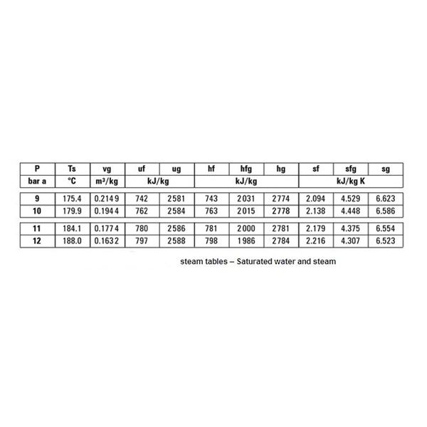 The steam table shown above is a saturated water and steam table. As all the other tables are used on the same principle, we will only discuss this one. For an absolute pressure of 9 bars, the saturation temperature is 175.4 C. It means that at a temperature of 175.4 and above C all of the steam will be saturated. Of course, any temperature above this will be super heating of the steam.
It must be noted however that at 175.4 C, depending on the latent heat supplied for vaporization, the steam can have any dryness faction. Vg is the specific volume of steam, hf is the specific enthalpy of water, hg is the specific enthalpy of steam, sf is the specific entropy of water, and sg is the specific entropy of steam.
We will now become familiar with this formula:
h = hf + xL
Where x is dryness fraction and L = hg – hf
By the above formula, if we know the dryness fraction of steam, we can calculate the enthalpy of wet steam, and its value would lie between that of the saturated water and saturated steam.
For example, if the dryness fraction is 0.8 for steam at 9 bars absolute pressure in bars.
Referring to the steam table above, hf = 743 kJ/Kg, L = 2031 kJ/Kg,
h = 743 + 0.8 x 2031 = 2367.8 kJ/Kg