Unit IV
Engineering mechanics
The Parallelogram of Forces Method is one of the graphical methods developed to find the resultant of a coplanar force system. Two or more concurrent forces can be replaced by a single resultant force that is statically equivalent to these forces.

The illustration shows two vectors and their resultant. The resultant force is shown as the dashed vector. In order to resolve these forces graphically, one must first extend the lines of action of two concurrent forces until they intersect. This intersection is known as the point of origin for the system. Both forces, as well as the resultant, must ALL act either away from or toward the point of origin.
The resultant can be represented graphically by the diagonal of the parallelogram formed by using the two force vectors to determine the length of the sides of the parallelogram. The magnitude of the resultant can be accurately measured as the scaled length of the diagonal. The resultant MUST go through the point of intersection of its components!!!
 (Remember: graphical solutions depend upon the accuracy of the drawing. The length of each vector should be carefully scaled to equal the magnitude of the force).
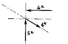
More than two non-parallel forces can be combined by successively eliminating one of the forces. Combine any two of the forces into their resultant by the parallelogram method. Combine this resultant with any of the remaining forces (or with the resultant of any of the remaining forces) until all of the forces are included. One must remember that the vectors can only be translated (or moved) along their lines of action. Two vectors (or Forces) cannot be combined (or resolved) until both of them are meeting head-to-head or tail-to-tail!
The Triangle of Forces Method is another graphical method developed to find the resultant of a coplanar force system. Since the opposite sides of a parallelogram are equal, a force triangle may also be found instead of using the parallelogram method. This method is quite useful because it can be successively applied to any number of concurrent forces.

To calculate the resultant of the force system shown above, move force A so that it's tail meets the head of force B. Now forces A and B form a "Head-to-Tail" arrangement. The resultant R is found by starting at the tail of B (the point of intersection of forces A and B) and drawing a vector which terminates at the head of the transposed A. Note that if force B had been transposed instead of force A, the resultant would have started from the tail of A and terminated at the head of force B. Again, this process could be repeated for any number of force vectors.
The resultant is described by the vector's magnitude and direction. These are determined by scaling the length and angle respectively. The accuracy of these values depends upon the accuracy of the graphics.
More than two non-parallel, non-concurrent forces can be combined by successively eliminating one of the forces. Combine any two of the forces into their resultant by the triangle method, and then extend that resultant until it intersects the line of action of another force. One continues this process until all forces have been included. In this way, each one of the forces is successively combined with the resultant of the previous triangle. One cannot simply continue to add the vectors head-to-head or tail-to-tail because the resulting lines of action would then be incorrect!
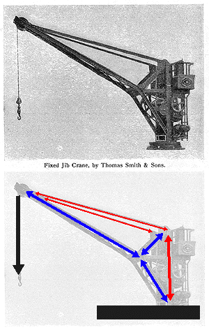 This illustration of a fixed jib crane allows one to read the forces as they meet at the tip of the boom. The diagram indicates the forces acting in the crane: red for tension and blue for compression.
The graphical methods of force decomposition could be used to determine the magnitude of the forces within the crane. In this case the two components for each of the structural elements are shown. All of the vectors are representational. They are not drawn to scale. The actual magnitudes are simply determined IF one would actually draw ALL of the vectors to scale and then measure the results.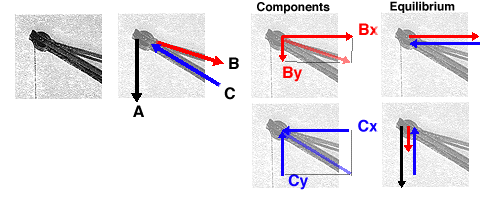
Free-body diagrams are diagrams used to show the relative magnitude and direction of all forces acting upon an object in a given situation. A free-body diagram is a special example of the vector diagrams that were discussed in an earlier unit. These diagrams will be used throughout our study of physics. The size of the arrow in a free-body diagram reflects the magnitude of the force. The direction of the arrow shows the direction that the force is acting. Each force arrow in the diagram is labelled to indicate the exact type of force. It is generally customary in a free-body diagram to represent the object by a box and to draw the force arrow from the centre of the box outward in the direction that the force is acting. An example of a free-body diagram is shown at the right.
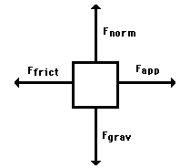
The free-body diagram above depicts four forces acting upon the object. Objects do not necessarily always have four forces acting upon them. There will be cases in which the number of forces depicted by a free-body diagram will be one, two, or three. There is no hard and fast rule about the number of forces that must be drawn in a free-body diagram. The only rule for drawing free-body diagrams is to depict all the forces that exist for that object in the given situation. Thus, to construct free-body diagrams, it is extremely important to know the various types of forces. If given a description of a physical situation, begin by using your understanding of the force types to identify which forces are present. Then determine the direction in which each force is acting. Finally, draw a box and add arrows for each existing force in the appropriate direction; label each force arrow according to its type. If necessary, refer to the list of forces and their description in order to understand the various force types and their appropriate symbols.
Bow's Notation is a labelling convention whereby the space in between any group of forces is labelled with a capital letter such that each force is then straddled by two letters. Since, within a Framed Structure all forces are assumed to be carried within the frame Members, it follows that all spaces within a frame are also labelled such that each Member is also straddled by two letters as shown.
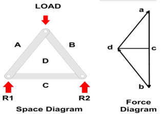
Labelling is carried out clockwise around the frame and each joint is then considered in turn, starting with the joint where there is sufficient data to draw a Force Diagram.
In the example shown:
We can assume the Load is known and, working clockwise around the joint at the apex, the Vector can be drawn, scaled to its magnitude, and labelled with a direction arrow as creating a force a down to b - since we know the load acts downwards (note the convention to use lower case letters on Force Diagrams).
The Lines of Action of the force within Members BD and DA are given by the frame drawing (or Space Diagram) and can be drawn through b and a respectively to intersect in d.
It is a feature of Force Diagrams that the lines of force will follow each other around a Force Polygon and so, given the downwards direction of ab, it can be seen that, around the apex, the forces within both BD and DA are pointing upwards.
Since all Members must stay still, or be in Equilibrium there must be equal and opposite forces at the lower ends of BD and DA (i.e. AD and DB) indicating that the these Members are Struts - which is what we would expect.
This additional information can be used to determine other forces (e.g. The Reactions) by working clockwise around the two lower joints and adding dc for example, to the Force Diagram.
1. The equilibrium constant has a definite value for every reaction at a particular temperature.
2. The value of equilibrium constant is independent of the original concentration of reactants.
3. The value of equilibrium constant tells the extent to which a reaction proceeds in the forward or reverse direction. If the value of K is larger, then the equilibrium concentration of the components on the right hand side of the reaction will be greater than the components on the left hand side of the reaction. Hence, the reaction proceeds to a greater extent and vice versa.
4. The equilibrium constant is independent of the presence of catalyst. This is because the catalyst affects the rate of forward reaction and backward reactions equally.
5. For a reversible reaction, the equilibrium constant for the forward reaction is inverse of the equilibrium constant for the backward reaction i.e., Kf=1/(Kb)
Trusses are simply defined as triangulation of members to make the stabilized structure. Triangulation is the stable configuration mathematically. Generally, a truss has the members called as top chord, bottom chord, vertical chord and diagonal chord. The main functions of the trusses are:
- Carrying the loads from the over structures
- Providing adequate lateral stability to the entire structure
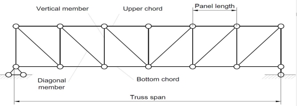
There are some basic assumptions in the designing process. It should be clarified that the construction of the trusses should conform with the design assumptions to avoid the unwanted failures due to the dispersion of the forces and loads. Following are the assumptions in truss design.
- Truss members will carry only the axial forces
- The nodes i.e. the connections of the members are designed as pinned joints so that moments won’t be transferred to the members of the truss
- All the external loads and the reactions are act only on the nodes
- Generally, the truss should be in a plane.
Typically the members of the trusses are made as I sections, angles, T sections, Tube sections, Square sections and channel sections. I sections are more preferable as a optimized section in terms of the structural forces.
TYPES OF TRUSSES
- Simple truss – indicates a single triangular truss. These trusses are most often used as the roof trusses.
- Planar truss – as the name implies it is a two dimensional truss. If all the members and the nodes are in a planar surface, then this truss is a planar truss.
- Space frame truss – Contrast to planar truss, the members and the nodes are located in the three dimensional space. Electrical and telecom towers are the one of the simplest example that we are seeing in the day to day life.
Simple Truss: It is possible to create a simple truss by joining three bars together to form a triangle. We can increase the size of the truss by adding two more members with an additional joint. By repeating this process, we can develop simple trusses with different shapes as shown below. The triangular building block assures internal stability of the truss structure as it is increased in size.

Although it is possible to have non-triangular cells in a simple truss, internal stability will not be guaranteed in that case.
Compound Truss: A compound truss is made up of simple trusses joined together to form a larger truss. The figure below shows a compound truss consisting of two simple trusses joined by a common joint and a bar. It is also possible to have multiple simple trusses joined together to create a larger compound truss. The connection of simple trusses then becomes a design issue determined based on the size of the resulting compound truss. Compound trusses are commonly used to support loads over long spans as in bridges.
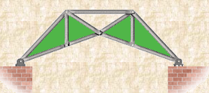
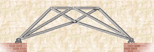
Complex Truss: A complex truss uses a general layout of members different from that used in simple and compound trusses. It often incorporates overlapping members.
FORMS OF TRUSSES
1. Pratt truss
 Pratt truss form for the loads in gravity direction
 Pratt truss form for the uplift loads(loads opposite to gravity)
2. Warren truss

3. North light truss

4. Vierendeel truss

King post truss, Bowstring truss, Queen post truss, Flat truss, Lenticular truss are some other forms of trusses in the use of the industry.
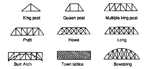
Following are the assumptions made in finding the forces in the members of a frame.
- The frame is a perfect frame
- The frame is loaded only at the joint
- All the members of the frame are pin-jointed
- Self-weight of the members is neglected.
Forces in various members of a perfect frame may be found out either by analytical method or graphical method. Here, the discussion is confined to only analytical method.
A perfect frame can be analytically analysed by the following methods:
1 Method of joints or method of resolution
2 Method of sections or method of moments
Question 1) Determine the forces in all members of truss by joint method
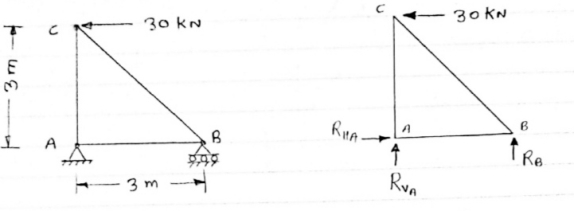
Answer 1) Consider FAB of Truss, Applying conditions of equilibrium,
 = 0
= 0
RHA + 30 Kn
 = 0
= 0
RvA + RB =0
Taking moment at point A, = 0
= 0
-(RB* 3) - (30*3) = 0
RB = -30 KN
RB =30 KN RVA = 30 KN
Consider Joint c, Assuming forces in member AC & BC to be
Tensile, applying conditions of equilibrium, 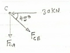
 = 0
= 0
-30 + FCB cos 45 =0
FCB =30/cos 45 = 42.42 KN (T)
-  = 0
= 0
- FcA – FCB sin 45=o
- F cA -42.42 sin 45 =0 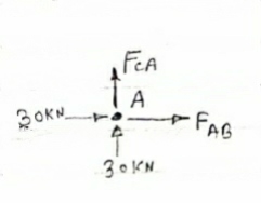
-FCA – 30= 0
-FCA = -30 KN
Consider Joint c, assuming forces in member AC & BC to be
Tensile, applying conditions of equilibrium,
 Fx = 0 30+FAB =0
FAB = -30KN
Question 2) Determine the forces in each member of the plane truss as shown in fig. In terms pf the external loading and state if the members are in tension or compression. Use 0+ 30 deg, L = 2 m and p =100N.
Diagram
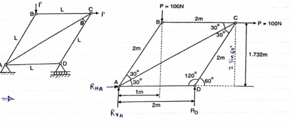
Answer 2) Consider FBD of Truss,
For equilibrium,  Fx =0
Fx =0
RHA+100 =0
RHA =-100 KN
 Fy =0 RVA = RD – 100 ….. 1
MA = 0 -------Taking moment @ A
- (Roxz) + (100*1) + (100*1.732) =0
- - 2 Rd + 100 + 1.7320 =0
- -2 Rd + 100 + 173.2 =0
- RD =136.66 N ()
From eqn (1)
RVA = 100 – 136.6
RVA= 36.6N
RVA = 36.6 N
Consider Joint D, for equilibrium,
Fx =0
-FAD + FCD cos 60 =0 – (11)
Fy = 0
136.6 +FCD sin 60 +0 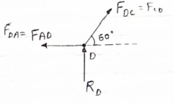
FCD = -157.73 N ©
From eqn (11), Fad =- 78. 87 N (c)
Consider point A, for the equilibrium of point A,
 Fx = 0
- 100 + FAD + FAc cos + 30 FAb cos60 = 0
-100 + (-78.87) +FAC cos 30 +FAb cos60 =0
FAc cos 30 + FAB cos60 + 178. 87 (3)
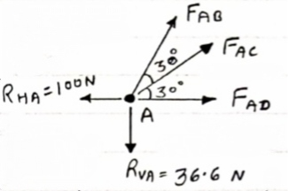
 fx =0
fx =0
-36.6 + FAC sin 30 + FAB sin 60 =0
FAC sin 30 + FAb sin 60 = 36.6
Solving eqn (3) and (4)
FAC = 273.21 N (T)
FAB = -115.47 N
FAB= 115.47 N ©
Consider point B, for the equilibrium of point,
 Fx =0
Fx =0
-FAB cos60 + FBC =0
-[9-115.47) cos60]+ FBC =0
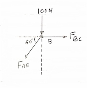
FBC = -57.73 N
FBC =57.73N
Member | AB | BC | CD | AD | AC |
Force | 115.47N | 57.73N | 157.73N | 78.87N | 273.21N |
Nature | c | c | c | c | T |
Question 3) Determine the axial forces in each member of the plane truss as shown in figure.
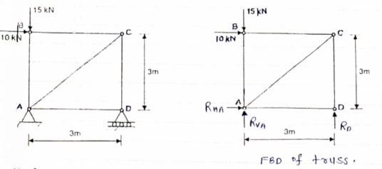
Answer 3) consider FBD of Truss,
For the equilibrium of Truss,  fx =0
fx =0
RHA + 10 =0
RHA = -10 KN
RHA =10KN (
Resolving forces vertically,
 fy =o
fy =o
RVA + RD -15 =0
RVA + RD = 15 …… (1)
Taking moment about point A,
 Fy =0
Fy =0
(10*3) – 3 Rd =0
30+ 3 Rd =0
RD= 10 KN 
RVA = 5KN ( )
)
Now Consider joint B, FBD of joint B is shown below.
Assumbing forces developed in all members to be Termile,
For the equilibrium of joint We have
 fx =0
fx =0
10+FBC =0 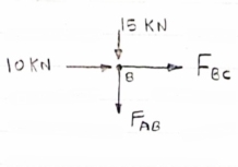
FBC = -10 KN
FBC = 10KN (c)
 fy =0
fy =0
FAB = -15 KN
FAB = 15 KN (c)
Now consider joint c,
For the equilibrium of joint,
 fx =0
fx =0
-FBC – FAC cos 45 =0
- (-10) – FAC cos 45=0
10= FAC cos 45
FAC = 10/cos 45 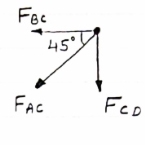
FAc = 14.14 KN (T)
 fy =0
fy =0
-Fac sin 45 – FCD=0
- 14.14 sin45 = FCD
FCD = -10 KN (c)
FCD= 10 KN (c)
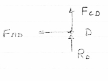
Consider joint D,
By observation,
FAD=0
Sr .No | Member | Force | Nature |
1 | AB | 15 KN | c |
2 | BC | 10KN | c |
3 | CD | 10KN | c |
4 | DA | 0 | - |
5 | AC | 14.14 | T |
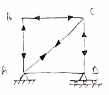
Question 4) Member AB & BC can support a maximum compressive force of 800 N & members AD, DC, BD can support a max. Tensile. Force of 2000N Determine the greatest land p that
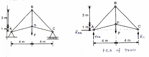
Answer 4) Consider following geometry of the figure.
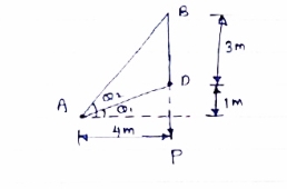
Tan 1 = ¼
1 = ¼
 14.04
14.04
 2 =
2 =  =45
=45
 Consider
 fx =0 RHA = 0
∈Fy =o RVA + Rc = p………(1)
∈ma =0
Hp- 8 Rc =0
Rc =P/2 N ( ) RvA = (P/2) N (
 )
)
Consider point A C assuming all forces as Tensile)
∈fx =0
FAD cos 14.04+FAB cos 45 =0… (2)
∈fy = 0 p/2= Fad sin 14.04 + FAB sin 45 =0….. (3)
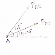
FAB = 2743.9 N > 800 N ( Not Allowed)
Let FAD = 2000 N (T) Then from eqn (2) & (3)
FAB =-274.9 N > 800 ( Not allowed)
Let FAB = .800 N ©, Then put this eqn (2) (3) we get
FAB = 583 N < 2000 N (Allowed) From Eqn (2) P= 848.9 N
Method of joint: This method involves isolating each joint of the truss and considering the equilibrium of the joint when determining the member axial force. Two equations used in determining the member axial forces are ∑ Fx = 0 and ∑ Fy = 0. Joints are isolated consecutively for analysis based on the principle that the number of the unknown member axial forces should never be more than two in the joint under consideration in a plane trust.
Analysis of Trusses by Method of Joint
This method is based on the principle that if a structural system constitutes a body in equilibrium, then any joint in that system is also in equilibrium and, thus, can be isolated from the entire system and analyzed using the conditions of equilibrium. The method of joint involves successively isolating each joint in a truss system and determining the axial forces in the members meeting at the joint by applying the equations of equilibrium. The detailed procedure for analysis by this method is stated below.
Procedure for Analysis
•Verify the stability and determinacy of the structure. If the truss is stable and determinate, then proceed to the next step.
•Determine the support reactions in the truss.
•Identify the zero-force members in the system. This will immeasurably reduce the computational efforts involved in the analysis.
•Select a joint to analyse. At no instance should there be more than two unknown member forces in the analysed joint.
•Draw the isolated free-body diagram of the selected joint, and indicate the axial forces in all members meeting at the joint as tensile (i.e. as pulling away from the joint). If this initial assumption is wrong, the determined member axial force will be negative in the analysis, meaning that the member is in compression and not in tension.
•Apply the two equations Σ Fx = 0 and Σ Fy = 0 to determine the member axial forces.
•Continue the analysis by proceeding to the next joint with two or fewer unknown member forces.

Method of section: This method entails passing an imaginary section through the truss to divide it into two sections. The member forces are determined by considering the equilibrium of the part of the truss on either side of the section. This method is advantageous when the axial forces in specific members are required in a truss with several members.

Analysis of Trusses by Method of Section
Sometimes, determining the axial force in specific members of a truss system by the method of joint can be very involving and cumbersome, especially when the system consists of several members. In such instances, using the method of section can be timesaving and, thus, preferable. This method involves passing an imaginary section through the truss so that it divides the system into two parts and cuts through members whose axial forces are desired. Member axial forces are then determined using the conditions of equilibrium. The detailed procedure for analysis by this method is presented below.
Procedure for Analysis of Trusses by Method of Section
•Check the stability and determinacy of the structure. If the truss is stable and determinate, then proceed to the next step.
•Determine the support reactions in the truss.
•Make an imaginary cut through the structure so that it includes the members whose axial forces are desired. The imaginary cut divides the truss into two parts.
•Apply forces to each part of the truss to keep it in equilibrium.
•Select either part of the truss for the determination of member forces.
•Apply the conditions of equilibrium to determine the member axial forces.