Unit – V
Engineering mechanics
Centre of gravity, in physics, an imaginary point in a body of matter where, for convenience in certain calculations, the total weight of the body may be thought to be concentrated. The concept is sometimes useful in designing static structures (e.g., buildings and bridges) or in predicting the behaviour of a moving body when it is acted on by gravity.

When a drum is stood on end, its centre of gravity (CG) is firmly supported, and the drum is in stable equilibrium (A). If the drum is tilted slightly to either side (B), the pull of gravity on this centre creates a torque, or turning force, around the new point of support and pulls the drum back to the stable position. A drum balanced on its rim (C) is in unstable equilibrium. Even a tiny displacement (D) will create a torque that will turn the drum farther from the unstable position.
In a uniform gravitational field the centre of gravity is identical to the centre of mass, a term preferred by physicists. The two do not always coincide, however. For example, the Moon’s centre of mass is very close to its geometric centre (it is not exact because the Moon is not a perfect uniform sphere), but its centre of gravity is slightly displaced toward Earth because of the stronger gravitational force on the Moon’s near side.
The location of a body’s centre of gravity may coincide with the geometric centre of the body, especially in a symmetrically shaped object composed of homogeneous material. An asymmetrical object composed of a variety of materials with different masses, however, is likely to have a centre of gravity located at some distance from its geometric centre. In some cases, such as hollow bodies or irregularly shaped objects, the centre of gravity (or centre of mass) may occur in space at a point external to the physical material—e.g., in the centre of a tennis ball or between the legs of a chair.
Published tables and handbooks list the centres of gravity for most common geometric shapes. For a triangular metal plate such as that depicted in the figure, the calculation would involve a summation of the moments of the weights of all the particles that make up the metal plate about point A. By equating this sum to the plate’s weight W, multiplied by the unknown distance from the centre of gravity G to AC, the position of G relative to AC can be determined. The summation of the moments can be obtained easily and precisely by means of integral calculus.
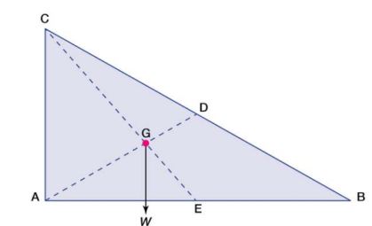
Centre of gravity. The red dot is the centre of gravity G.
The centre of gravity of anybody can also be determined by a simple physical procedure. For example, for the plate in the figure, the point G can be located by suspending the plate by a cord attached at point A and then by a cord attached at C. When the plate is suspended from A, the line AD is vertical; when it is suspended from C, the line CE is vertical. The centre of gravity is at the intersection of AD and CE. When an object is suspended from any single point, its centre of gravity lies directly beneath that point.
Centroid Definition
The centroid is the centre point of the object. The point in which the three medians of the triangle intersect is known as the centroid of a triangle. It is also defined as the point of intersection of all the three medians. The median is a line that joins the midpoint of a side and the opposite vertex of the triangle. The centroid of the triangle separates the median in the ratio of 2: 1. It can be found by taking the average of x- coordinate points and y-coordinate points of all the vertices of the triangle.
Centroid Theorem
The centroid theorem states that the centroid of the triangle is at 2/3 of the distance from the vertex to the mid-point of the sides.

Suppose PQR is a triangle having a centroid V. S, T and U are the midpoints of the sides of the triangle PQ, QR and PR, respectively. Hence as per the theorem;
QV = 2/3 QU, PV = 2/3 PT and RV = 2/3 RS
Centroid of A Right Angle Triangle
The centroid of a right angle triangle is the point of intersection of three medians, drawn from the vertices of the triangle to the midpoint of the opposite sides.
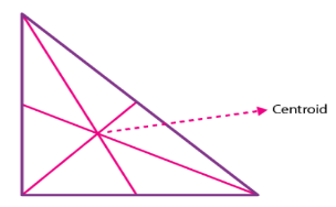
Centroid of a Square
The point where the diagonals of the square intersect each other is the centroid of the square. As we all know, the square has all its sides equal. Hence it is easy to locate the centroid in it. See the below figure, where O is the centroid of the square.
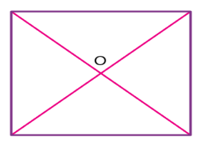
Properties of centroid
The properties of the centroid are as follows:
- The centroid is the centre of the object.
- It is the centre of gravity.
- It should always lie inside the object.
- It is the point of concurrency of the medians.
Centroid Formula
Let’s consider a triangle. If the three vertices of the triangle are A(x1, y1), B(x2, y2), C(x3, y3), then the centroid of a triangle can be calculated by taking the average of X and Y coordinate points of all three vertices. Therefore, the centroid of a triangle can be written as:
Centroid of a triangle = ((x1+x2+x3)/3, (y1+y2+y3)/3)
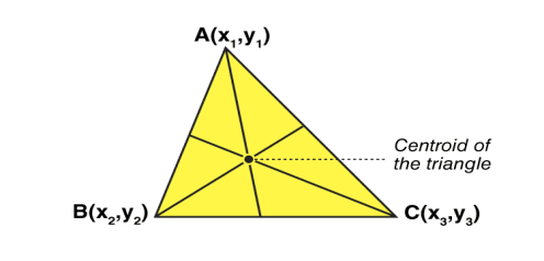
Area moment of inertia
When a distributed loading whose intensity varies linearly acts perpendicular to an area, the computation of the moment of the loading distribution about an axis involves a quantity called the moment of inertia of the area or simply area moment of inertia.
Consider a differential plate, subjected to fluid pressure P that varies linearly with depth, as shown in fig, such that  , where,
  is the specific weight of fluid.
The force acting on a acting on the differential area of the plate is given by

The moment of this this force about the x-axis is

Integrating  over the entire area of the plate yields


The integral part of the moment equation is called area moment of inertia about x-axis 

Similarly, area moment of inertia about y-axis is given as,

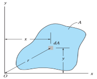
Moment of Inertia for area can also be given as

Where, A is the total area
And k is referred as radius of gyration
Radius of gyration for area of a plate about an axis is defined as the radial distance to a point which would have a same moment of inertia as the plate’s actual distribution of area, if the total area of the plate were concentrated.
It is given by,

Moment Of Inertia of Cylinder
The moment of inertia of cylinder about a perpendicular axis passing through its centre is determined by;
Ix = ¼ MR2 + 1/12 ML2
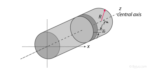
We will look at the derivation of this formula below.
Generally, the derivation involves 3 primary steps. It includes;
- Splitting the cylinder into infinitesimally thin disks and stating the moment of inertia.
- Using both parallel and perpendicular axis theorems to determine the expression.
- Integrating over the length of the cylinder.
1. Cutting the cylinder into infinitesimally thin disks
We will consider the cylinder having mass M, radius R, length L and the z-axis which passes through the central axis.
Here,
Density ρ = M / V
Next, we will consider the moment of inertia of the infinitesimally thin disks with thickness dz.
First, we assume that dm is the mass of each disk, We get;
Dm = ρ X Volume of disk
Dm = M / V X (πr2.dz)
We take V = area of circular face X length which is = πr2L. Now we obtain;
Dm = M / πr2L X (πr2.dz)
Dm = M / L X dz
The moment of inertia about the central axis is given as;
Dlz = ½ dmR2
Use of Perpendicular Axis Theorem
We now apply the perpendicular axis theorem which gives us;
Dlz = dlx + dly
Here, if we need to consider that both x and y moments of inertia are equal by symmetry.
Dlx = dly
We need to combine the equations for the perpendicular axis theorem and symmetry. We get;
Dlx = dlz / 2
Now we substitute lz from the equation above.
Dlx = ½ x ½ dmR2
Dlx = ¼ dmR2
Alternatively, for the x-axis, we use the parallel axis theorem to find the moment of inertia. We get;
Dlx = ¼ dmR2 + dmz2
Integration
Now we conduct integration over the length of the cylinder to express the mass element dm in terms of z. We take the integral from z=0 to z=L.
Ix = o∫L dlx
Ix = o∫L ¼ dzR2 + o∫L ¼ z2 m / l dz
Ix = ¼ M / L R2z + M / L Z3 / 3]0L
Since it is a definite form of integral we ignore the constant. We will now have;
Ix = ¼ M / L R2 L + M / 3L 2L3 / 23
Ix = ¼ MR2 + 1/12 ML2
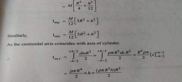
Therefore, I =1/2 MR2
Moment Of Inertia of Sphere
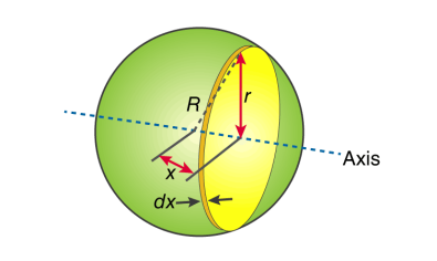
First, we take the moment of inertia of a disc that is thin. It is given as;
I = ½ MR2
In this case, we write it as;
DI (infinitesimally moment of inertia element) = ½ r2dm
Find the dm and dv using;
Dm = p dV
p = moment of a thin disk of mass dm
Dv = expressing mass dm in terms of density and volume
DV = π r2 dx
Now we replace dV into dm. We get;
Dm = p π r2 dx
And finally, we replace dm with dI
DI = ½ p π r4 dx
The next step involves adding x to the equation. If we look at the diagram we see that r, R and x form a triangle. Now we will use Pythagoras theorem which gives us;
r2 = R2 – x2
Now if we substitute the values we get;
DI = ½ p π (R2 – x2)2 dx
This leads to:
I = ½ p π -R∫R (R2 – x2)2 dx
After integration and expanding we get;
I = pπ 8/15 R5
Additionally, we have to find the density as well. For that we use;
P (density) = M (mass) / V (volume)
p = M (mass) / (4/3 πR3)
If we substitute all the values;
I = 8/15 π [M / (4/3 πR3)] R5
I = ⅖ MR2
Moment of inertia of Solid Cone
We will take a solid cone where its axis will pass through the centre with radius = r, height = h. We will need to determine the mass though.
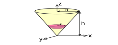
We take the elemental disc whose mass is given by;
Dm = ρ ⋅ π r2dz
Density is given as;
ρ = M / V = M / (⅓ π R2h)
With this, we will calculate the dm.
Dm = [M / (⅓ π R2h)] X π r2dz
Dm = (3M / R2h) X r2 dz
If we consider the similarity of the triangle, then we have;
R / r = h / z
r = R .z / h
Now,
Dm = (3M / R2h )⋅( R2 / h2) ⋅ z2dz
Dm = (3M / h3 ). z2dz
If we consider z-axis, the moment of inertia of the elemental disk will be;
DI = ½ dmr2
DI = ½ ⋅ (3M / h3 ) . z2 ⋅ (z2 R2 / h2) dz
DI = 3 / 2 ⋅ M R2 / h5 X z4dz
Now we will follow the integration process. Here;
I = 3 / 2 ⋅ M R2 / h5 o∫h z4dz
I = 3 / 2 ⋅ M R2 / h5 [z5 / 5 ]oh
I = 3 / 2 ⋅ M R2 / h5 ⋅ h5 / 5
Therefore, I = 3/10 MR2
The moment of inertia of a body about an axis is sometimes represented using the radius of gyration. Now, what do you mean by the radius of gyration? We can define the radius of gyration as the imaginary distance from the centroid at which the area of cross-section is imagined to be focused at a point in order to obtain the same moment of inertia. It is denoted by k.
Radius of Gyration Formula
The formula of moment inertia in terms of the radius of gyration is given as follows:
I = mk2 (1)
Where I is the moment of inertia and m is the mass of the body
Accordingly, the radius of gyration is given as follows
k=√ I/m (2)
The unit of the radius of gyration is mm. By knowing the radius of gyration, one can find the moment of inertia of any complex body equation (1) without any hassle.
Consider a body having n number of particles each having a mass of m. Let the perpendicular distance from the axis of rotation be given by r1, r2, r3,…,rn. We know that the moment of inertia in terms of radius of gyration is given by the equation (1). Substituting the values in the equation, we get the moment of inertia of the body as follows

………… (3)
If all the particles have the same mass then equation (3) becomes

We can write mn as M which signifies the total mass of the body. Now the equation becomes

………… (4)
From equation (4), we get
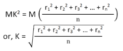
From the above equation, we can infer that the radius of gyration can also be defined as the root-mean-square distance of various particles of the body from the axis of rotation.
What is the use of radius of gyration?
The radius of gyration is used to compare how various structural shapes will behave under compression along an axis. It is used to predict buckling in a compression beam or member.
The product of inertia is defined as
The x and y terms inside the integral denote the centroidal position of the differential area measured from the y and x axes, respectively. Similar to moments of inertia discussed previously, the value of product of inertia depends on the position and orientation of selected axes. It is possible for the product of inertia to have a positive, negative, or even a zero value.
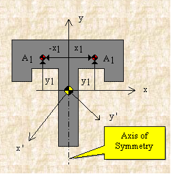
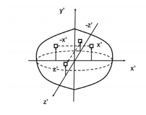
If, for example, either x or y represents an axis of symmetry, then the product of inertia Ixy would be zero. To see why this is the case, take a look at the figure to the right. Consider the small area A1 to the right of y axis at the distance of x1. Then consider a similar area to the left of this axis of symmetry at the distance of -x1. Since both areas are at the same vertical position from the x-axis, they have the same value of y. The contribution from the left area is -x1yA1 and that from the right is x1yA1 which add up to zero. Since every point on one side of the axis of symmetry has an equal counterpart on the other side, the total value of the integral would be zero.
However, if we were to consider the product of inertia with respect to the x' and y' axes, then Ix'y' would not be zero. We will have more discussion about the product of inertia in the section on principal axes.
For a general three-dimensional body, it is always possible to find 3 mutually orthogonal axes (an x, y, z coordinate system) for which the products of inertia are zero, and the inertia matrix takes a diagonal form. In most problems, this would be the preferred system in which to formulate a problem. For a rotation about only one of these axis, the angular momentum vector is parallel to the angular velocity vector. For symmetric bodies, it may be obvious which axis is principle axis. However, for an irregular-shaped body this coordinate system may be difficult to determine by inspection; we will present a general method to determine these axes in the next section. But, if the body has symmetries with respect to some of the axis, then some of the products of inertia become zero and we can identify the principal axes.
For instance, if the body is symmetric with respect to the plane  then, we will have
  and
and  will be a principal axis. This can be shown by looking at the definition of the products of inertia.
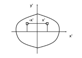
The integral for, say,  can be decomposed into two integrals for the two halves of the body at either side of the plane
 . The integrand on one half
  will be equal in magnitude and opposite in sign to the integrand on the other half (because
  will change sign). Therefore, the integrals over the two halves will cancel each other and the product of inertia
  will be zero. (As will the product of inertia
  ) Also, if the body is symmetric with respect to two planes passing through the center of mass which are orthogonal to the coordinate axis, then the tensor of inertia is diagonal, with
Another case of practical importance is when we consider axisymmetric bodies of revolution. In this case, if one of the axes coincides with the axis of symmetry, the tensor of inertia has a simple diagonal form. For an axisymmetric body, the moments of inertia about the two axis in the plane will be equal. Therefore, the moment about any axis in this plane is equal to one of these. And therefore, any axis in the plane is a principal axis. One can extend this to show that if the moment of inertia is equal about two axis in the plane (IP P = Ixx), whether or not they are orthogonal, then all axes in the plane are principal axes and the moment of inertia is the same about all of them. In its inertial properties, the body behaves like a circular cylinder.

The tensor of inertia will take different forms when expressed in different axes. When the axes are such that the tensor of inertia is diagonal, then these axes are called the principal axes of inertia.
The Search for Principal Axes and Moments of Inertia as an Eigenvalue Problem
Three orthogonal principal axes of inertia always exist even though in bodies without symmetries their directions may not be obvious. To find the principle axis of a general body consider the body shown in the figure that rotates about an unknown principal axis. The total angular momentum vector is  in the direction of the principle axis. For rotation about the principal axis, the angular momentum and the angular velocity are in the same direction.
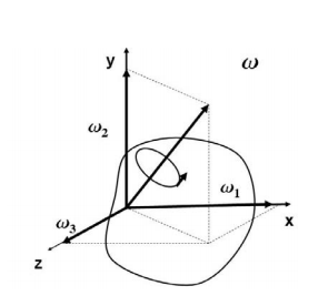
We seek a coordinate axes x, y and z, about which a rotation ωx, ωy and ωz, which is aligned with this coordinate direction, will be parallel to the angular momentum vector and related by the equation

We then express the general form for angular momentum vector in components along the x, y and z axis in term of the components of ω along these axes using the general form of the inertia tensor in the x, y, z system, we have

At this point in the process we know the inertia tensor in an arbitrary x, y, and z system and are seeking the special orientation of ω which will align the angular momentum HG with the angular velocity ω. Collecting terms from equation(11) on the left-hand side, we obtain

The structure of the solution for finding the principal axes of inertia and their magnitudes is a characteristic value problem. The three eigenvalues give the directions of the three principal axis, and the three eigenvectors give the moments of inertia with respect to each of these axis. In principal directions, the inertia tensor has the form

- Point load
Load acting at a single point on the beam is known as point load. Its unit is N or kN

2. Uniformly Distributed load (UDL) or Rectangular Load:
A load which is spread over the beam or part of the beam uniformly is known as UDL
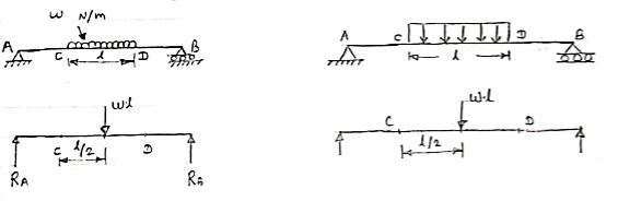
Conversion of UDL or Rectangular load into point load
= Intensity of UDL × distance
= w. l. ------------- N
3. Uniformly varying load or Triangular load:
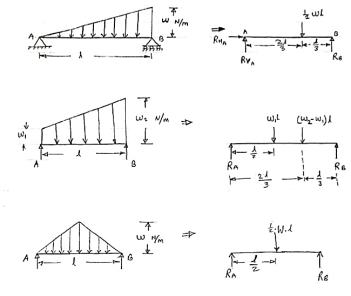
A load whose intensity is linearly varying between the two points on the beam is known as UVL. If an intensity of the load at one end is zero and at other ends is maximum then it is called as uniformly varying load or triangular load.
Following figures shows different types of UVL
- To convert UVL into point load, calculate the area of uniformly varying load.
- For location of point load find x coordinate of centroid of the UVL area.
Classification of statically determinate beams
- Cantilever beams
- Simply supported beams
- Overhanging beams.
Types of applied loads on the beams
- Concentrated loads
- Uniformly distributed loads
- Uniformly varying loads
- Externally applied moments.
Definitions
Shear force: The resultant vertical force either to the right or to the left of the section is known as shear force.
Bending moment: The algebraic sum of the moments of all forces either to the left or the right at a section in a beam is known as bending moment.
Shear force diagram: A diagram in which ordinate represents shear force and abscissa represents the position of the section is called shear force diagram.
Bending moment diagram A diagram in which ordinate represents bending moment and abscissa represents the position of the section is called bending moment diagram.
SFD and BMD for Standard Cases
1. Cantilever subjected to:
- a concentrated load at free end
- Uniformly distributed load over entire span
- Uniformly varying load over entire span
2. Simply supported beam subjected to:
- a concentrated load
- Uniformly distributed load over entire span
- Uniformly varying load over entire span
- An external moment
3. Overhanging beam subjected to a concentrated load at free end.
Nature of SF and BM variation
Load S.F. B.M.
- No load Constant Linear
- Uniformly distributed load Linear Parabolic
- Uniformly varying Parabolic Cubic
- Maximum shear force and bending
- Moment values for standard cases
Maximum shear force and bending moment values for standard cases
