Unit 1
D.C. Circuits
- Voltage Source: A voltage source always have a resistance in series.
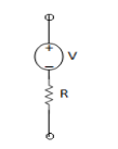
Ideal source
R = 0
Practical = 2 - 5Ω
I = 0

2. Current Source: Always have R parallel with the source.
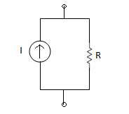
(R) Practical = Mega Ω
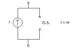
Ideal =  I =
I =

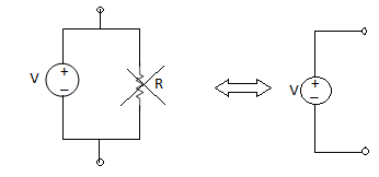
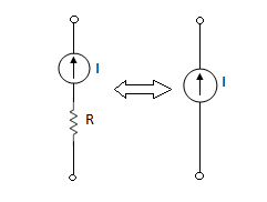
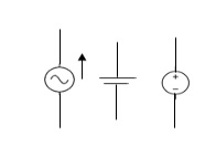
Few either
AC or DC 
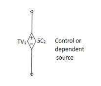
dc

Units and dimensions
Current:
The rate of flow of charge across a cross-section of the conducting material is called as current.
i = 
q= charge in coulombs
t= time in seconds
Power: The rate at which energy is generated. It is energy per unit time. Units is watt.
P= E/t
Energy: It is work done by a force of one newton acting over a distance of one meter.
E= Fl
F=m*a
F= force
m=mass
a=acceleration
- From VI:
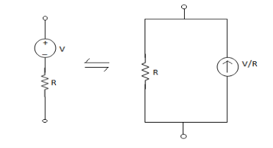
2. From IV:
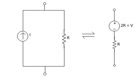
Ohms Law: It states that the current in the electric circuit is directly proportional to the voltage across the two points
V α I
V= IR
V = voltage across terminals in volts
R = resistance in ohms
I= current in Amperes
KCL:
It is defined as a node, nodes may be simple node, principle node.
Simple Node interconnection of two branches
Principle Node interconnection of at least two branches
Definition:
In a lumped electric circuit , for any of its node at any time ‘t’, the algebric sum of all the currents, leaving the node is zero.
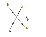
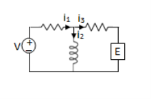


 (on integration)
★ Charge conservation is dependent on KCL.
FEATURES:
- The KCL applies to any lumped electric circuit, it does not matter whether elements are linear - non linear, active - passive, time-invariant - time-variant etc. i.e. the KCL is independent of the nature of element connected to the node.
- Since, there is no accumulation of charge at any node (KCL expression) the conservation of charge at each and every node in lumped circuit is expressed by KCL.
2. KVL:
In a lumped electric circuit for any of its nodes at any time ‘t’, the algebraic sum of branch voltages around the loop is zero.
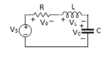
VS = VR + VL+VC
Work Done (W) = qV


★ KVL gives Law of Conservation of energy.
Features:
- It is independent of nature of element present in the loop.
- KVL expression provides the law of conservation of energy in a lumped electric circuit.
SUPERPOSITION THEOREM
- This is only applicable to circuits with linear elements.
- If two or more than two independent sources (voltage or current) are operating in the circuit than voltage across any element or current through any element is sum of current and voltages due to individual sources.
Question 1. Find the current through  resistance.
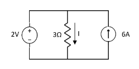
Solution:
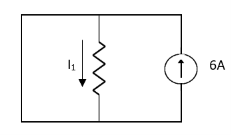
 1 = 0
1 = 0
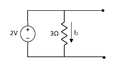
 2 =
2 =
 1 +
1 +  2
2 
Special Case:
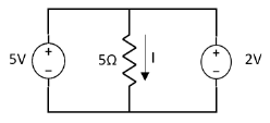
Since two voltage sources with different magnitude in parallel which cannot be connected as in single branch two different current is not possible (if 5V than I = zero).
Question:
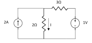
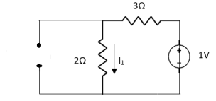
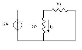
 1 =
1 = 
 2 =
2 = 
=
 1 +
1 +  2
2
= 
THEVENIN’S AND NORTON’S THEOREM

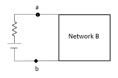
Thevenin’s equivalent of A
Norton’s equivalent of A
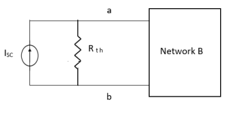
 sc = Vth/Rth
- Norton’s equivalent is obtained by source conversion of thevenin’s equivalent circuit.
CONDITIONS FOR APPLICATION
- For network A:
- Network A should contain linear elements.
- Network A can have independent and dependent current and voltage source.
- If network A has dependent source than controlling parameter must lie in network A itself.
- Network A should not have any source coupling and magnetic coupling.
- For network B:
- It can have linear and non linear elements.
- It can have dependent and independent voltage and current sources.
- It should not have any source and magnetic coupling with network A.
Method for finding Rth :
Firstly, open circuit terminal A and B.
- If network is operating with only independent sources:
- Make all sources zero in network A.
- Find out the equivalent resistance across terminal A and B.
2. If network A is operating with independent and dependent sources:
- Make all independent sources zero in network A.
- Connect a generation between A and B.
3. If network is operating with only dependent sources:
Connect generation between A and B

Method for Vth:
First open circuit terminal A and B.
Find out the voltage between A and B this is Vth
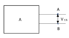
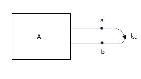
Method for Isc:
- Isc =

- Remove network B and S.C. The terminal A and B and current from terminal A to B Isc.
Question: Find Vth and Rth
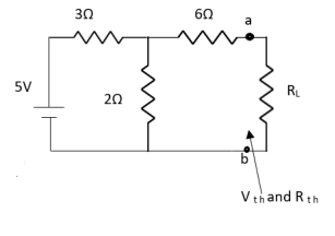
Answer:
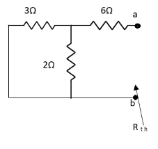


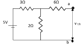


Finding Isc from circuit directly:
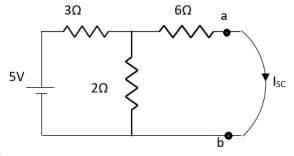
By KCL,


Question:
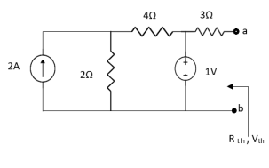
Answer
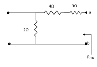
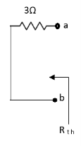
Also, clear from circuit that Vth = 1V.
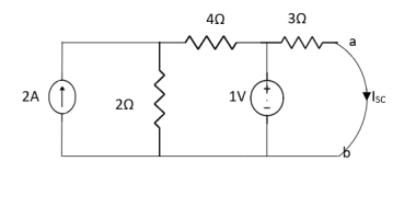
By applying KVL we get,
1-3Isc=0
Isc= A
A
Que:
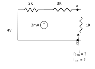
Ans;
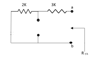
Rth=3k+2k=5k
By applying KVL we get


Therefore, 
Question:
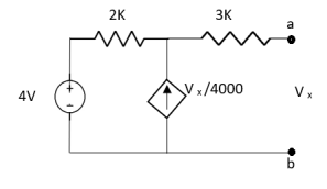
Solution: For Rth
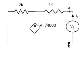
By KCL,


But, 


By KVL,


Question:
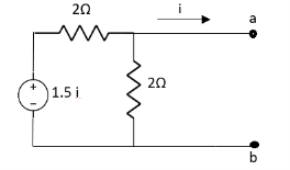
Solution: Since, no independent source is present so,
Isc = 0
And we know that,


Since Rth cannot be zero
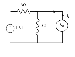


But 


Question: Find out the Norton’s equivalent
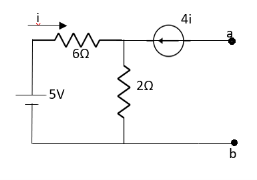
Solution:
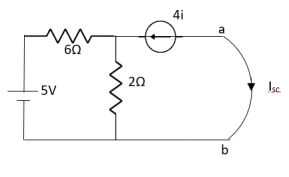
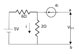

Since, there is no significance of current source


 A
A
Power: The rate at which energy is generated. It is energy per unit time. Units is watt.
P= E/t
Energy: It is work done by a force of one newton acting over a distance of one meter.
E= Fl
F=m*a
F= force
m=mass
a=acceleration
LOOP ANALYSIS
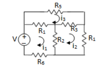
For Loop 1 with il

For Loop 2 with i2

For Loop 3 with i3

Example 1. For the circuits given below write the voltage equations:
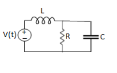
Solution: Let current i1be in loop 1 current and i2 for loop 2
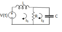


B.
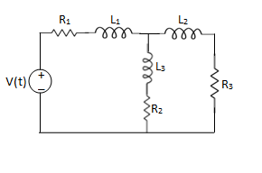
Solution:
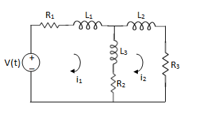
For loop 1

For loop 2

NODE ANALYSIS
For these we assume every node as a voltage point and write the current equation for every element. For current source, current entering is negative.
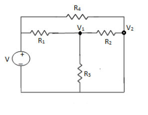
For node V1

For node V2

For V

Example: Using nodal analysis find voltage across 5resistor.
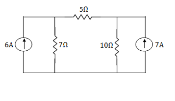
Solution:
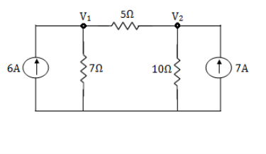
For V1


 1
1
For V2


 2
2
Solving 1 and 2:


For 5 voltage = 
= -50.9 + 57.27
= 6.37V
