Unit 2
Ac circuit
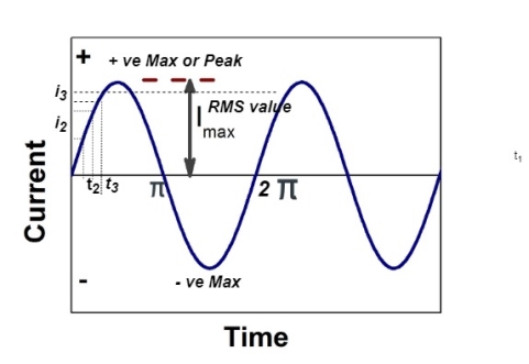
When a coil is placed in uniform magnetic field. When coil rotates in opposite direction at constant angular velocity the emf is induced in the coil. The magnitude of emf induced depends on the flux cut by the conductor. The magnitude of induced emf becomes maximum when conductor is perpendicular to the lines of forces. The direction of emf induced is determined by Flemings right hand rule.
Average Value:
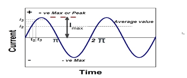
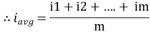
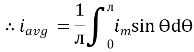
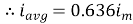
The arithmetic mean of all the value over complete one cycle is called as average value
 =
= 
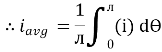
For the derivation we are considering only hall cycle.
Thus  varies from 0 to ᴫ
i = Im Sin
Solving
We get

Similarly, Vavg=
The average value of sinusoid ally varying alternating current is 0.636 times maximum value of alternating current.
Root mean square value
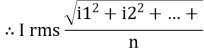
The RMS value of AC current is equal to the steady state DC current that required to produce the same amount of heat produced by ac current provided that resistance and time for which these currents flows are identical.
I rms = 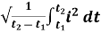
Direction for RMS value:
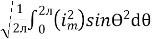
Instantaneous current equation is given by
i = Im Sin 
But 
I rms = 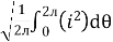
= 
=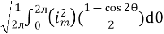
=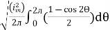
Solving
=
=
Similar we can derive
V rms=  or 0.707 Vm
 the RMS value of sinusoidally alternating current is 0.707 times the maximum value of alternating current.
Form Factor:
Form Factor = 
For sine wave form factor = 
Peak factor of AC quantity
Peak factor = 
For sine wave =  2
2
The alternating quantities (voltages and currents) in practice are represented by straight lines having definite direction and length. Such lines are called the phasors and the diagrams in which phasors represent currents, voltages and their phase difference are known as phasor diagrams.
Though phasor diagrams can be drawn to represent either maximum or effective values of voltages and currents but since effective values are of much more importance, phasor diagrams are mostly drawn to represent effective values.
In order to achieve consistent and accurate results it is essential to follow certain conventions.
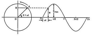
The above figure shows that OA is the maximum ac quantity present. The OA represents emf on vertical axis. This phasor of OA in ACW direction represents sinusoidal voltage or current. Its angular velocity is one revolution complete in same time as by the alternating voltage or current.
The ACW is taken positive for phasor. In series circuit current phasor is taken as reference as the current is same. In parallel circuit voltage is taken as reference as it is same throughout.
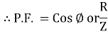
Power factor (P.F.)
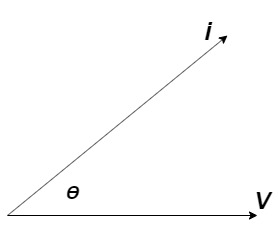
It is the cosine of angle between voltage and current
If Ɵis –ve or lagging (I lags V) then lagging P.F.
If Ɵ is +ve or leading (I leads V) then leading P.F.
If Ɵ is 0 or in phase (I and V in phase) then unity P.F.
Impedance (Z)
The ac circuit is to always pure R pure L and pure C it well attains the combination of these elements. “The combination of R1 XL and XC is defined and called as impedance represented as
Z = R +i X
Ø = 0
 only magnitude
R = Resistance, i = denoted complex variable, X =Reactance XL or Xc
Polar Form
Z =  L I
L I
Where  =
=
 Measured in ohm
Admittance:
The reciprocal of impedance is admittance. Its unit is mho (siemens)
Y=  =
= 
V=IZ
I=VY
Y=  =
= 
Y= G+iB
G= 
B= 
Real Power: [P]
It is nothing but the actual power being used in a circuit.
P= = I2R Watts
Reactive Power: [Q]
It is the function of reactance in the circuit X. Mainly reactive loads are inductor and capacitors. These elements dissipate zero power. These element shows that they dissipate power. This is called as reactive power.
Q= = I2X VAR (volt-Ampere-Reactive)
Apparent Power: [S]
It is the product of a circuit voltage and current without reference to phase angle. It is the combination of both reactive and real power.
S= = I2Z VA (volt-Ampere)
FOR RL Circuit
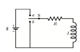
Fig: Series RL circuit
After switch is closed applying KVL
 =0
=0
This is first order homogeneous differential equation so
 dt
dt
Integrating both sides
Ln i=  t+K
t+K
Taking antilog of both sides
i=k
At t=0
i(0)= =I0
=I0
 =ke0
=ke0
The particular solution is given as
i=  for t≥0
= for t<0
FOR RC Circuit
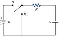
Fig: Series RC circuit
 =V
=V
For t>0 applying KVL
Ri(t)+ +V=0
+V=0

Hence general solution of above equation is calculated same as for RL circuit
i=k
i(0)=- 
Hence, particular solution for network is given as
i=-  for t for t≥0
= for t<0
Time Constant
Time constant for RL circuit
From above section for RL circuit at t≥0
i= 
i=I0
I0= 
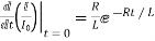
Time taken for current to drop from unity to zero is called as time constant T.

 sec
sec
FOR RC Circuit
It can be calculated in the same manner as for series RL circuit
The time constant is given as 
T=RC
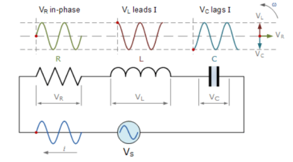
The series RLC circuit is shown below. Let current i(t) be sinusoidal. The value of instantaneous voltage across R is in phase with current. The instantaneous voltage across L leads current by 900. The instantaneous voltage across C lags current by 90o.
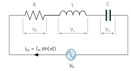
Writing the loop equations, we get
Vs-VR-VL-VC=0
VS-IR-L -
- = 0
= 0
VS= IR + L +
+ 
The voltage triangle will be
Vs=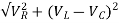
VR = iRsin t
t
VL= iXLsin t+90)
t+90)
VC= iXcsin t-90)
t-90)
Z = =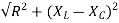
Impedance Z= 
Que) For a series RLC circuit having R=10ohms, L= 0.15H, C=100 F. They are connected across 100v 50Hz supply. Calculate total impedance?
Sol: Impedance Z= 
Z=  = 18.27ohm
Que) For a series RLC circuit having R=12ohms, L= 0.2H, C=60 F. They are connected across 100v 50Hz supply. Calculate circuit current?
Sol: I= 
Z= 
Z=  = 13.89ohm
I = 100/13.89 =7.2A
Que) For a series RLC circuit having R=10ohms, L= 0.15H, C=100 F. They are connected across 100v 50Hz supply. Calculate power factor?
Sol: cosφ = 
Impedance Z= 
Z=  = 18.27ohm
Cosφ =  =
= 
φ = 56.81o lagging
Que) A coil takes a current of 6A when connected to 24V dc supply. To obtain the same current with 50HZ ac, the voltage required was 30V. Calculate inductance and p.f of coil?
Sol: The coil will offer only resistance to dc voltage and impedance to ac voltage
R =24/6 = 4ohm
Z= 30/6 = 5ohm
XL = 
= 3ohm
Cosφ =  = 4/5 = 0.8 lagging
Que) The potential difference measured across a coil is 4.5V,when it carries a dc current of 8A. The same coil when carries ac current of 8A at 25Hz,the potential difference is 24V. Find current and power when supplied by 50V,50Hz supply?
Sol: R=V/I= 4.5/8 = 0.56ohm
At 25Hz Z= V/I=24/8 =3ohm
XL = 
= 2.93ohm
XL = 2 fL = 2
 x 25x L = 2.93
L=0.0187ohm
At 50Hz
XL = 2x3 =6ohm
Z =  = 5.97ohm
I= 50/5.97 = 8.37A
Power = I2R = 39.28W
Que) A coil having inductance of 50mH an resistance 10ohmis connected in series with a 25 F capacitor across a 200V ac supply. Calculate resonant frequency and current flowing at resonance?
Sol: f0= = 142.3Hz
I0 = V/R = 200/10 = 20A
Que) A 15mH inductor is in series with a parallel combination of 80ohm resistor and 20 F capacitor. If the angular frequency of the applied voltage is 1000rad/s find admittance?
Sol: XL = 2 fL = 1000x15x10-3 = 15ohm
XL = 1/ C = 50ohm
Impedance of parallel combination Z = 80||-j50 = 22.5-j36
Total impedance = j15+22.5-j36 = 22.5-j21
Admittance Y= 1/Z = 0.023-j0.022 siemens
Que) A circuit connected to a 100V, 50 Hz supply takes 0.8A at a p.f of 0.3 lagging. Calculate the resistance and inductance of the circuit when connected in series and parallel?
Sol: For series Z =100/0.8 = 125ohm
Cosφ = 
R = 0.3 x 125 = 37.5ohm
XL =  = 119.2ohm
XL = 2 fL = 2
 x 50x L
119.2 = 2 x 50x L
L= 0.38H
For parallel:
Active component of current = 0.8 cosφ = 0.3x0.3 = 0.24A
R = 100/0.24 =416.7ohm
Quadrature component of current = 0.8 sinφ = 0.763
XL= 100/0.763 = 131.06ohm
L= 100/0.763x2 x50 = 0.417H
i) It gives more smooth power delivery
Ii) The ripple factor in rectifier is less.
Iii) We can use 3-phase to supply 1-phase system
Iv) If there is problem in one of the phases in 3-phase supply the other two windings can be used in open delta.
v) For same amount of electric power, the 3-phasetransformers are smaller than the 1-phase.
Vi) The power factor is better than 1-phase.
Vii) The 3-phase motors like induction motors are self started
Viii) The 3-phase system require less conductor material for power transmission and distribution.
In three phase the windings are separated by 1200 each. The voltage produced in those windings are 1200 apart from each other. Below shown is one coil RR’ and two more coils YY’ and BB’ each having phase shift of 1200.
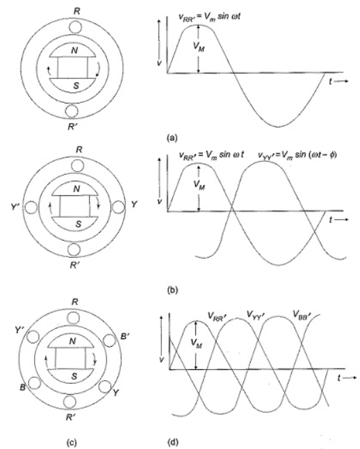
The instantaneous value of voltages is given as
VRR’ = Vmsinωt
VYY’ = Vmsin(ωt-120)
VBB’ = Vmsin(ωt-240)
The three phase voltages are of same magnitude and frequency.
The change in voltage is in order VRR’- VYY’- VBB’. So, the three-phase are changed in that order and are called as phase change.
VRR’ = Vmsinωt
VYY’ = Vmsin(ωt-120)
VBB’ = Vmsin(ωt-240)
A balanced three phase load is one that is equally shared (balanced) across all three phases. The total load is determined by adding up the individual kW balanced loads.
The conversion formula is as follows
KW gen = kW load = kVA x PF = [√3 x volts x current x PF]/1000
PF = power factor of load
Volts = rated line to line voltage
Current = rated line current
An unbalanced 3 phase load is one in which the load is not equally distributed over all the three phases. To obtain the equivalent 3-phase rating the highest single phase loading must be multiplied by 3. An unbalanced load give rise to unequal phase to phase and phase to neutral voltages.
The formula is as follows: KW gen = [3 x volts (line to neutral) x current x PF]/1000
Star Connection:
In this type similar ends are connected to common point called as neutral and having a star shape. These connections are used in case of unbalanced current flowing in the three-phase. To avoid any kind of damage we use this connection.
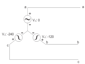
Line voltage VL =  Vphase
Line current IL = Iphase
Delta Connection:
There are three wires with no neutral. They are used for short distance due to unbalanced current in circuit.
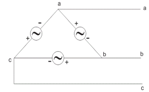
Line voltage VL = Vphase
Line current IL =  Iphase
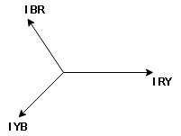
- Phasor Diagram
Consider equation ①
Note : we are getting resultant line current IR by subtracting 2 phase currents IRY and IBR  take phase currents at reference as shown
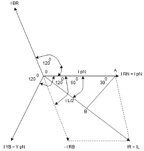
Cos 300 = 
 =
= 
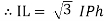
- Complete phases diagram for delta connected balanced Inductive load.
Phase current IYB lags behind VYB which is phase voltage as the load is inductive
- Power relation for delta load star power consumed per phase
PPh = VPh IPh Cos Ø
For 3 Ø total power is
PT= 3 VPh IPh Cos Ø …….①
For star
VL and IL = IPh (replace in ①)
 PT = 3
  IL Cos Ø
 PT = 3
  VL IL Cos Ø – watts
For delta
VL = VPh and IL =  (replace in ①)
PT = 3VL
= 3VL  Cos Ø
Cos Ø
 PT
PT VL IL Cos Ø – watts
Total average power
P =  VL IL Cos Ø – for ʎ and
  load
load
K (watts)
Total reactive power
Q =  VL IL Sin Ø – for star
  delta load
K (VAR)
Total Apparent power
S =  VL IL – for star
  delta load
K (VA)


