Unit V
Reciprocating Machines
Working principle of steam engine:
Steam engine is a device which converts heat energy into mechanical energy and heat is supplied into the engine through the medium of steam. This is a Machine where steam is used as a working substance. Steam engine works on the principle of first law of thermodynamics where work and heat are mutually convertible.
In a steam engine there is a cylinder fitted with a piston. Then steam from the boiler enters to the engine cylinder and the cylinder is made act on the piston which thereby reciprocates to and fro motion of the piston. So, heat energy in the steam is converted into mechanical work, thus, it is called Reciprocating steam engine.
In a steam engine, high-pressure superheated steam from boiler is fed into the steam chest. Here a D-shaped valve V called D-slide valve, moves to and fro in a steam chest and this valve regulates the supply of steam into the engine cylinder is operated by a mechanism E, called eccentric which is situated on the crankshaft. There are two different ports A and B in which steam is led into the cylinder on the two sides of the piston and K is the exhaust port in which steam is led out of the cylinder.
When D slide valve moves to the right, steam from steam chest enters from the left side through port A. This high-pressure steam pushes the piston to the right side of the crank end. This is called the forward stroke of the piston. With the movement of piston, crosshead moves to the right thus pushing the connecting rod which also pushes the crank to the right side. Now the crank and crankshaft both rotate in clockwise direction show in the picture.
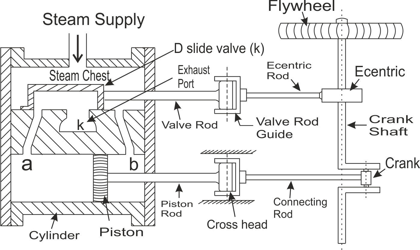
When piston is in extremely right side or nearer to crank end cover, the V valve is moving towards the left direction and open the steam port B in which steam is entering into the cylinder through this port. So, the piston is now moving left side direction or away from the crank. This is called the returned stroke of the piston. The piston is starting to move in left direction and left side steam leaves the cylinder through the exhaust port K via port A.
Again, when the piston is in the extreme left condition, the valve V are starting to move the right direction and open the port A. As a result, steam enters the cylinder through port A and piston starts to move at right direction. Now the right-side cylinder's steam leaves the cylinder through the exhaust port K via port B.
In this way, the piston is moving to and fro motion in the cylinder's chamber and it circulates crankshaft through piston rod, connecting rod and crank. This process is continuously running and as such the steam engine works. At the end of each stroke, the piston changes its direction of motion and it is momentarily stopped. This is called dead centres of the crank. The above steam engine is called single cylinder double acting horizontal reciprocating steam engine.
II) Carnot cycle:
The most efficient heat engine cycle is the Carnot cycle, consisting of two isothermal processes and two adiabatic processes. The Carnot cycle can be thought of as the most efficient heat engine cycle allowed by physical laws. When the second law of thermodynamics states that not all the supplied heat in a heat engine can be used to do work, the Carnot efficiency sets the limiting value on the fraction of the heat which can be so used.
In order to approach the Carnot efficiency, the processes involved in the heat engine cycle must be reversible and involve no change in entropy. This means that the Carnot cycle is an idealization, since no real engine processes are reversible and all real physical processes involve some increase in entropy.
The Carnot cycle consists of the following four processes:
- A reversible isothermal gas expansion process. In this process, the ideal gas in the system absorbs qin amount heat from a heat source at a high temperature Thigh expands and does work on surroundings.
- A reversible adiabatic gas expansion process. In this process, the system is thermally insulated. The gas continues to expand and do work on surroundings, which causes the system to cool to a lower temperature, Tlow
- A reversible isothermal gas compression process. In this process, surroundings do work to the gas at Tlow, and causes a loss of heat, qout.
- A reversible adiabatic gas compression process. In this process, the system is thermally insulated. Surroundings continue to do work to the gas, which causes the temperature to rise back to Thigh.
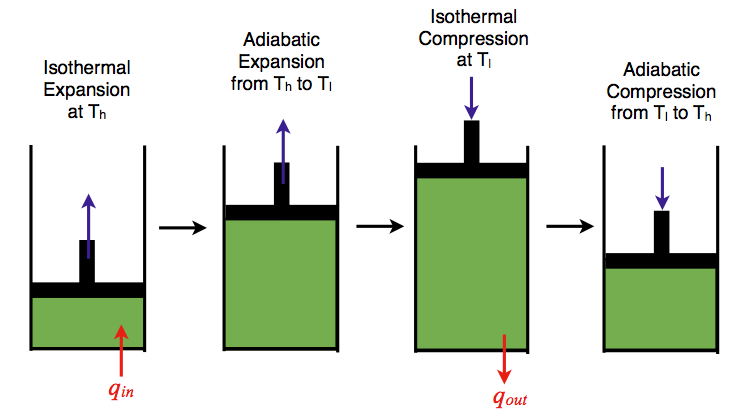 Figure 1: An ideal gas-piston model of the Carnot cycle.
P-V Diagram
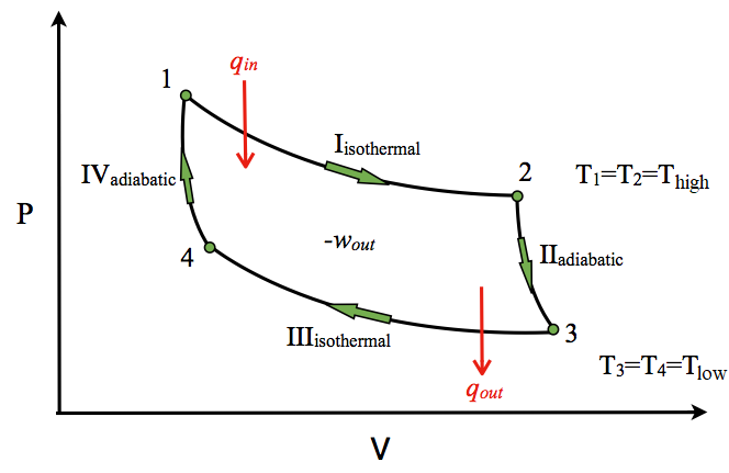
The P-V diagram of the Carnot cycle is shown in Figure. In isothermal processes I and III, ∆U=0 because ∆T=0. In adiabatic processes II and IV, q=0. Work, heat, ∆U, and ∆H of each process in the Carnot cycle are summarized below.
T-S Diagram
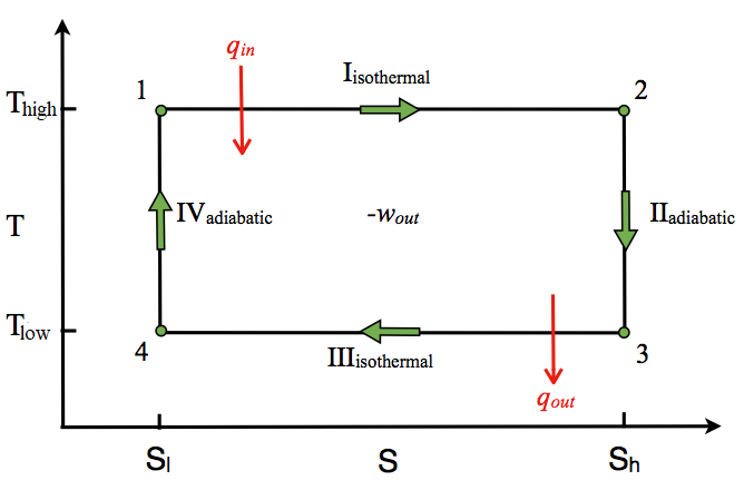
The T-S diagram of the Carnot cycle is shown in Figure In isothermal processes I and III, ∆T=0. In adiabatic processes II and IV, ∆S=0 because dq=0. ∆T and ∆S of each process in the Carnot cycle are shown in Table.
Steps involved in a Carnot Cycle
For an ideal gas operating inside a Carnot cycle, the following are the steps involved:
Step 1:
Isothermal expansion: The gas is taken from P1, V1, T1 to P2, V2, T2. Heat Q1 is absorbed from the reservoir at temperature T1. Since the expansion is isothermal, the total change in internal energy is zero, and the heat absorbed by the gas is equal to the work done by the gas on the environment, which is given as:
W1→2=Q1=μ×R×T1×ln (v2 / v1)
Step 2:
Adiabatic expansion: The gas expands adiabatically from P2, V2, T2 to P3, V3, T3.
Here, work done by the gas is given by:
W2→3= μR / γ−1 (T2−T3)
Step 3:
Isothermal compression: The gas is compressed isothermally from the state (P3, V3, T3) to (P4, V4, T4).
Here, the work done on the gas by the environment is given by:
W3-4= μRT2ln (v3 / v4)
Step 4:
Adiabatic compression: The gas is compressed adiabatically from the state (P4, V4, T4) to (P1, V1, T1).
Here, the work done on the gas by the environment is given by:
W4-1 = μR / γ−1 (T4−T1)
Hence, the total work done by the gas on the environment in one complete cycle is given by:
W=W1-2+W2-3+W3-4+W4-1
W = μ×R×T1×ln (v2 / v1) + μR / γ−1 (T2−T3) + μRT2ln (v3 / v4) + μR / γ−1 (T4−T1)
W= μ x R x T1 x ln (v2/ v1) – μ x R x T2 ln (v3 / v4)
Net efficiency = Net work done by the gas / Heat absorbed by the gas
Net efficiency = W / Q
= Q1−Q2 / Q1=1−Q2 / Q1
=1− [T2 ln (v3 / v4)/ T1 ln (v2 / v1)]
Since the step 2 to 3 is an adiabatic process,
We can write T2V2Ƴ-1 = T3V3Ƴ-1
Or,
v2 / v3= (T2 / T1)1/ γ−1
Similarly, for the process 4 to 1, we can write
v1 / v2 = (T2 / T1)1/ γ−1
This implies,
v2 / v3= v1 / v2
So, the expression for net efficiency of Carnot engine reduces to:
1− [T2 ln (v3 / v4)/ T1 ln (v2 / v1)] :( ln (v3 / v4)/ ln (v2 / v1) cancel out)
Net efficiency = 1−T2 / T1
III) Otto cycle
Otto cycle is a thermodynamic cycle upon which a spark ignition engine works. Spark Ignition (or SI) engine uses petrol (or Gasoline) as fuel. Otto cycle was invented by Nicolas Otto in 1876.
Spark ignition engine is a type of internal combustion engines.
Below are P-V and T-S Diagrams of the Otto Cycle.
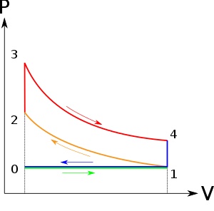
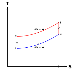
Otto Cycle is comprised of four processes (apart from the intake and exhaust process)
Process 1-2: This process comes after intake process. In case of SI engines, intake is a mixture of gasoline and air, also known as charge. In this process charge is compressed in isentropic manner. Temperature rose from T1 to T2 and volume decrease from V1 to V2.
Process 2-3: In this process the fuel gets blasted with the help of external spark (that is why the engine is known as spark ignition engine). This process is a constant volume heat addition process. Temperature raised from T2 to T3
.
Q2-3= CV(T3-T2)
Process 3-4: After the combustion process, the exhaust gases expend. This process is an isentropic expansion process. No heat is interchanged. The temperature falls from T3 to T4 and volume increase from V3 to V4.
Process 4-1: After the expansion process, exhaust valve opens. This results into sudden drop of pressure inside engine cylinder. This process is a constant volume heat rejection process.
Q4-1= CV (T4-T1)
Process 0-1 is the intake process and process 1-0 is the exhaust process.
Efficiency of the Otto Cycle is the ratio of work output to the heat input.
Work done or output = Heat Supply-Heat rejected
Work output = [CV (T3-T2)] – [CV (T4-T1)]
Heat Input = CV (T3-T2)
Efficiency = Work done / Heat Input
After putting values of heat input and work output in the above formula, we get
η= [CV (T3-T2)] – [CV (T4-T1)] / CV (T3-T2)
η = 1 – [(T4-T1)/ (T3-T2)]
η = 1 – [T1 (T4 / T1 – 1)/ T2 (T3/T2 - 1)]
r = compression ratio = V1 / V2 = V4 / V3
T2 = T1 (V1/V2) y-1
T2 = T1 (r) y-1 ……..equation 1
T3/T4 = (V4 /V3)y-1
T3 = T4 (r) y-1 ……equation 2
From equation 1 and 2
T2 / T1 = T3/T4
Or T4 / T1 = T3 / T2
Put the value in this equation
η = 1 – [T1 (T4 / T1 – 1)/ T2 (T3/T2 - 1)]
We get
η = 1 – [T1 / T2]
Or η = 1 – 1 / (r )y-1
IV) DIESEL CYCLE:
Since Carnot’s principle states that no engine can be more efficient than a reversible engine (a Carnot heat engine) operating between the same high temperature and low temperature reservoirs, the Diesel engine must have lower efficiency than the Carnot efficiency.
A typical diesel automotive engine operates at around 30% to 35% of thermal efficiency. About 65-70% is rejected as waste heat without being converted into useful work, i.e. work delivered to wheels. In general, engines using the Diesel cycle are usually more efficient, than engines using the Otto cycle. The diesel engine has the highest thermal efficiency of any practical combustion engine. Low-speed diesel engines (as used in ships) can have a thermal efficiency that exceeds 50%. The largest diesel engine in the world peaks at 51.7%.
In general the thermal efficiency, ηth, of any heat engine is defined as the ratio of the work it does, W, to the heat input at the high temperature, QH.

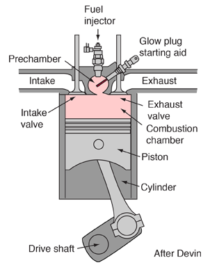
The diesel internal combustion engine differs from the gasoline powered Otto cycle by using a higher compression of the fuel to ignite the fuel rather than using a spark plug ("compression ignition" rather than "spark ignition").
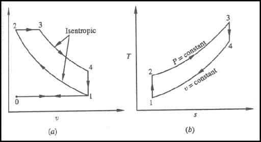
In the diesel engine, air is compressed adiabatically with a compression ratio typically between 15 and 20. This compression raises the temperature to the ignition temperature of the fuel mixture which is formed by injecting fuel once the air is compressed.
The ideal air-standard cycle is modelled as a reversible adiabatic compression followed by a constant pressure combustion process, then an adiabatic expansion as a power stroke and an iso volumetric exhaust. A new air charge is taken in at the end of the exhaust, as indicated by the processes a-e-a on the diagram.
Since the compression and power strokes of this idealized cycle are adiabatic, the efficiency can be calculated from the constant pressure and constant volume processes. The input and output energies and the efficiency can be calculated from the temperatures and specific heats:
Q1 = CP (T3-T2)
Q2 = CV (T4 – T1)
Efficiency = Q1-Q2/Q1
It is convenient to express this efficiency in terms of the
Compression ratio rC = V1/V2 = V4/V3 and the
CUT OFF ratio rE = V3/V2.
η = CP (T3-T2) - CV (T4 – T1) / CP (T3-T2)
Efficiency = η= 1- CV (T4 – T1) / CP (T3-T2)
Now using the ideal gas law PV=nRT and γ = CP/CV, this can be written
η = 1- 1/ γ [T1 (T4/T1-1) / T2 (T3/T2-1)]
From p-v t-s diagram
Process 1-2 is adiabatic compression process so that
T2 / T1= (V1/V2) γ-1
T2 / T1 = (rc) γ-1
Process 3-4 is adiabatic expansion process so that
T4 / T3 = (V3/V4) γ-1 = (V3 x V2 / V2 x V4) γ-1= (rE / rC ) γ-1
rE = V3/V2= T3 / T2
T4 / T1 = (T4 / T3) x (T3 / T2) x (T2 / T1)
T4 / T1 = (rE / rC ) γ-1 x ( rE)x (r) γ-1
T4 / T1= (rE ) γ
By putting all these valuesfinally, we get
η = 1- 1/ γ [T1 (T4/T1-1) / T2 (T3/T2-1)]
η = 1- 1/ (rc) γ-1 [(rE) γ – 1 / γ (rE -1)]
V) Duel cycle:
The combustion process in a spark ignition engine does not occur exactly at constant volume, nor does the combustion process in an actual compression ignition engine occur exactly at constant pressure, therefore another idealized cycle known as Dual cycle has been developed that more closely approximate the actual spark-ignition and compression-ignition engines. The p-v and T-s diagrams of Dual cycle are shown in Fig. 45.1. In this cycle, part of heat addition occurs at constant volume while the rest is at constant pressure. The dual cycle is also called mixed or limited pressure cycle.
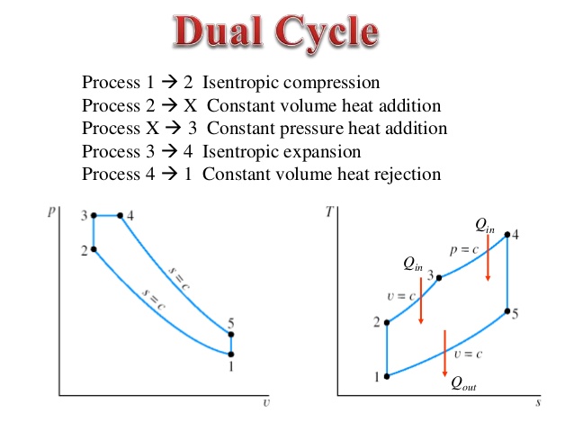
In a dual cycle, the system executing the cycle undergoes a series of five processes: two isentropic (reversible adiabatic) processes alternated with two isochoric process and one isobaric process:
Dual cycle – PV Diagram
Isentropic compression (compression stroke) – The gas is compressed adiabatically from state 1 to state 2, as the piston moves from intake valve closing point (1) to top dead centre. The surroundings do work on the gas, increasing its internal energy (temperature) and compressing it. On the other hand, the entropy remains unchanged. The changes in volumes and its ratio (V1 / V2) is known as the compression ratio. The compression ratio is smaller than the expansion ratio.
Isochoric compression (ignition phase) – In this phase (between state 2 and state 3) there is a constant-volume (the piston is at rest) heat transfer to the air from an external source while the piston is at rest at top dead centre. This process is similar to the isochoric process in the Otto cycle. It is intended to represent the ignition of the fuel–air mixture injected into the chamber and the subsequent rapid burning. The pressure rises and the ratio (P3 / P2) is known as the “explosion ratio”.
Isobaric expansion (power stroke) – In this phase (between state 3 and state 4) there is a constant-pressure (idealized model) heat transfer to the air from an external source (combustion of the fuel) while the piston is moving toward the V4. During the constant pressure process, energy enters the system as heat Qadd, and a part of work is done by moving piston.
Isentropic expansion (power stroke) – The gas expands adiabatically from state 4 to state 5, as the piston moves from V3 to bottom dead center. The gas does work on the surroundings (piston) and loses an amount of internal energy equal to the work that leaves the system. Again, the entropy remains unchanged.
Isochoric decompression (exhaust stroke) – In this phase the cycle completes by a constant-volume process in which heat is rejected from the air while the piston is at bottom dead centre. The working gas pressure drops instantaneously from point 5 to point 1. The exhaust valve opens at point 5. The exhaust stroke is directly after this decompression. As the piston moves from bottom dead centre (point 1) to top dead centre (point 0) with the exhaust valve opened, the gaseous mixture is vented to the atmosphere and the process starts anew.
During the Dual cycle, work is done on the gas by the piston between states 1 and 2 (isentropic compression). Work is done by the gas on the piston between stages 2 and 3 (isobaric heat addition) and between stages 2 and 3 (isentropicexpansion). The difference between the work done by the gas and the work done on the gas is the network produced by the cycle and it corresponds to the area enclosed by the cycle curve. The work produced by the cycle times the rate of the cycle (cycles per second) is equal to the power produced by the Diesel engine.
Thermal Efficiency for Dual Cycle
In general the thermal efficiency, ηth, of any heat engine is defined as the ratio of the work it does, W, to the heat input at the high temperature, QH.

The thermal efficiency, ηth, represents the fraction of heat, QH, that is converted to work. Since energy is conserved according to the first law of thermodynamics and energy cannot be be converted to work completely, the heat input, QH, must equal the work done, W, plus the heat that must be dissipated as waste heat QC into the environment. Therefore, we can rewrite the formula for thermal efficiency as:

Therefore, the heat added and rejected is given by:
Qadd-1 = mcv (T3 – T2)
Qadd-2 = mcp (T4 – T3)
Qout = mcv (T5 – T1)
Therefore, the thermal efficiency for a dual cycle is:

Two stroke petrol engines
In two stroke engine the working cycle is completed in two stroke of the piston or one revolution of crankshaft. This is achieved by carried out suction and compression in one stroke expansion and exhaust in the second stroke.
A two-stroke engine has port instead of valves. Opening and closing of the port are controlled by the piston
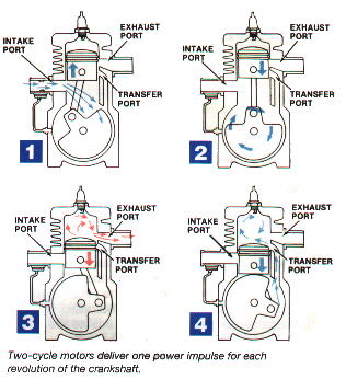
Following are the process in two stroke engines
1) Suction stroke: In this stroke piston while moving downward BDC (bottom dead centre) both the transfer port and exhaust port are open. The fresh fuel air mixture flows into the engine cylinder from crankcase.
2) Compression stroke: In this stroke, the piston while moving upwards, first cover the transfer port then exhausts port. After that fuel is compressed as the piston moves upwards. In this stage the inlet port opens and fresh air fuel mixture enters into crankcase.
3) Expansion stroke: During compression stroke the piston reached TDC (top dead centre) the charge is ignited with the help of spark plug. It suddenly increases the pressure and temperature of the product of combustion and volume remain constant. Due to rise in pressure the piston is pushed downwards with greater pressure. During the expansion some of the heat energy is produces and transform into mechanical work.
4) Exhaust stroke: In this stroke piston move downward and exhaust port is opened. The burned gases are exhaust from the engine cylinder through exhaust port into the atmosphere.
The two-stroke engines lighter, simpler and less expensive to manufacture. Two-stroke engines also have the potential to pack about twice the power into the same space because there are twice as many power strokes per revolution. The combination of light weight and twice the power gives two-stroke engines a great power-to-weight ratio compared to many four-stroke engine designs.
Two stroke diesel engines
In two stroke diesel engine the working cycle is completed in two stroke of the piston or one revolution of crankshaft. This is achieved by carried out suction and compression in one stroke expansion and exhaust in the second stroke.
A two-stroke engine has port instead of valves. Opening and closing of the port are controlled by the piston
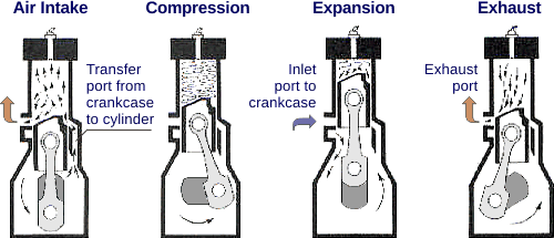
Following are the process in two stroke engines
1) Suction stroke: In this stroke piston while moving downward BDC (bottom dead centre) both the transfer port and exhaust port are open. The fresh fuel air mixture flows into the engine cylinder from crankcase.
2) Compression stroke: In this stroke, the piston while moving upwards, first cover the transfer port then exhausts port. After that air is compressed as the piston moves upwards. In this stage the inlet port opens and fresh air enters into crankcase.
3) Expansion stroke: During compression stroke the piston just before reached TDC (top dead centre) the fuel is injected in the form of very fine spray with the help of fuel injector valve. It suddenly increases the pressure and temperature of the product of combustion and volume remain constant. Due to rise in pressure the piston is pushed downwards with greater pressure. During the expansion some of the heat energy is produces and transform into mechanical work.
4) Exhaust stroke: In this stroke piston move downward and exhaust port is opened. The burned gases are exhaust from the engine cylinder through exhaust port into the atmosphere.
Four Stroke petrol and diesel engine:
Four stroke diesel engines:
In four stroke engine the working cycle is completed in four stroke of the piston or two revolution of crankshaft. This is achieved by carried out suction in one stroke and compression in second stroke, expansion in third stroke and exhaust in the fourth stroke. They have inlet and exhaust valve. Suction and compression in one revolution of crankshaft, expansion and exhaust in second revolution of crankshaft.
Following are the process in four stroke engines;
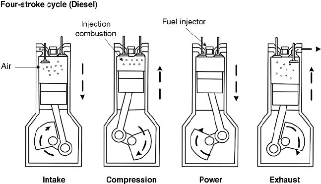
1) Suction stroke: In this stroke while piston moving downward BDC (bottom dead centre) inlet valve opens and pure air is sucked into the cylinder.
2) Compression stroke: In this stroke, the piston while moving from BDC to TDC, the inlet and outlet valve are closed. The compressed start as piston moves upwards. Which increase pressure and temperature. This complete one revolution of crankshaft
3) Expansion stroke: just before the piston reached the top dead centre fuel oil injected in the form of very fine spray into the cylinder. At this point temperature of the compressed air is sufficiently high to ignite the fuel which suddenly increases the pressure and temperature of combustion products. Due to increase in pressure the piston is pushed down with a great force.
4) Exhaust stroke: In this stroke exhaust valve open as piston move from BDC to TDC. This movement of the piston moves up and pushed out the burned gases to atmosphere from the engine cylinder
Four stroke petrol engines:
In four stroke engine the working cycle is completed in four stroke of the piston or two revolution of crankshaft. This is achieved by carried out suction in one stroke and compression in second stroke, expansion in third stroke and exhaust in the fourth stroke. They have inlet and exhaust valve. Suction and compression in one revolution of crankshaft, expansion and exhaust in second revolution of crankshaft.
Following are the process in four stroke engines;
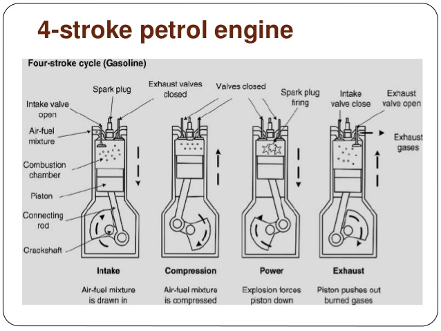
1) Suction stroke: In this stroke while piston moving downward BDC (bottom dead centre) inlet valve opens and air-fuel mixture is sucked into the cylinder.
2) Compression stroke: In this stroke, the piston while moving from BDC to TDC, the inlet and outlet valve are closed. The compressed start as piston moves upwards. Which increase pressure and temperature. This complete one revolution of crankshaft
3) Expansion stroke: just before the piston reached the top dead centre. The charge is ignited with the help of spark plug which suddenly increases the pressure and temperature of combustion products. But volume remains constant Due to increase in pressure the piston is pushed down with a great force.
4) Exhaust stroke: In this stroke exhaust valve open as piston move from BDC to TDC. This movement of the piston moves up and pushed out the burned gases to atmosphere from the engine cylinder
Compressor is a simple mechanical device which converts electrical energy into kinetic energy. Its main purpose is to provide high-pressure air for different industrial purposes. From filling the tires, manufacturing plants and small workshops all use high-pressure air to make their work easy and fast. Unlike the old fashion of using a single power source in the production plants and workshops, the use of air compressor is simple and helps in delivering high performance. It provides power to drills, sanders, nail guns, staplers and even sprays gun. The major advantage is that each tool now does not require bulky motors to run.
Here the air compressor motor runs all the equipment and converts electrical energy into kinetic energy. This makes them light, easy to use, increases performance and demands less repair. Let’s have a concise look at air compressor and its working principle.
An air compressor is a machine which presses the working fluid and pumps it to anywhere at the same time. Here the working fluid is always gas or air. It is a versatile device which compresses air at the notable pressure.
There are three types of compressors
- Reciprocating Air Compressor
- Rotary Air Compressor and
- Centrifugal Air Compressor
Reciprocating Air Compressor
A reciprocating compressor is a positive-displacement machine that uses a piston to compress a gas and deliver it at high pressure.
This type of compressor uses piston-cylinder arrangement to compress the air. Whenever something moves back and forth it is considered as moving in reciprocating motion. Similarly, in this type piston moves back and forth inside the cylinder and compress the air. There are two sets of valves that take care of air intake and exhaust.
The compressor takes inside successive amount of volume of air from intake valve and confined it in closed surface at that time piston moves downward with the closure of intake valve. Then there is compression of air by reducing its volume. Now the piston moves upward and compress the air and then displace the compressed air through exhaust valve. And then again intake take place and cycle repeat itself
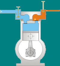
This type of compressor also called positive displacement machines. They are available in both as lubricated and oil-free.
The reciprocating compressor is single acting when the compressing is accomplished using only one side of piston and double acting when both the sides of piston used.
Major components of reciprocating compressor:
Reciprocating compressors are available in a variety of designs and arrangements. Major components in a typical reciprocating compressor are
- Frame
- Cylinders
- Distance Piece
- Piston
- Piston rings
- Cross Head
- Crankshaft
- Connecting Rod
- Valve
- Bearings
Some important parts are explained below:
Frame
The frame is a heavy, rugged housing containing all the rotating parts and on which the cylinder and crosshead guide is mounted. Compressor manufacturers rate frames for a maximum continuous horsepower and frame load.
Separable compressors are usually arranged in a balanced-opposed configuration characterized by an adjacent pair of crank throws that are 180 degrees out of phase and separated by only a crank web. The cranks are arranged so that the motion of each piston is balanced by the motion of an opposing piston.
Integral compressors typically have compressor and engine-power cylinders mounted on the same frame and are driven by the same crankshaft. Cylinders in integral compressors are usually arranged on only one side of the frame (i.e., not balanced-opposed).
Cylinder
The cylinder is a pressure vessel that contains the gas in the compression cycle. Single-acting cylinders compress gas in only one direction of piston travel. They can be either head end or crank end. Double-acting cylinders compress gas in both directions of piston travel. Most reciprocating compressors use double-acting cylinders.
Distance piece
The distance piece provides separation between the compressor cylinder and the compressor frame
Crankshaft
The crankshaft rotates around the frame axis and drives the connecting rod, piston rod, and piston.
Connecting rod connects the crankshaft to the crosshead pin
Crosshead converts the rotating motion of the connecting rod to a linear, oscillating motion that drives the piston
Piston rod connects the crosshead to the piston.
Piston and piston ring
The piston is located at the end of the piston rod and acts as the movable barrier in the compressor cylinder. Selection of material is based on strength, weight, and compatibility with the gas being compressed. The piston is usually made of a lightweight material such as aluminium or from cast iron or steel with a hollow centre for weight reduction. Thermoplastic wear (or rider) bands often are fitted to pistons to increase ring life and reduce the risk of piston-to-cylinder contact. Cast iron usually provides a satisfactorily low friction characteristic, eliminating the need for separate wear bands.
Wear bands distribute the weight of the piston along the bottom of the cylinder or liner wall. Piston rings minimize the leakage of gas between the piston and the cylinder or liner bore. Piston rings are made of a softer material than the cylinder or liner wall and are replaced at regular maintenance intervals. As the piston passes the lubricator feed hole in the cylinder wall, the piston ring gathers oil and distributes it over the length of the stroke.
Bearings
Bearings located throughout the compressor frame assure proper radial and axial positioning of compressor components. Main bearings are fitted in the frame to properly position the crankshaft. Crank pin bearings are located between the crankshaft and each connecting rod. Wrist pin bearings are located between each connecting rod and crosshead pin. Crosshead bearings are located at the top and bottom of each crosshead.
Most of the bearings in reciprocating compressors are hydrodynamic lubricated bearings. Pressurized oil is supplied to each bearing through oil supply grooves on the bearing surface. The grooves are sized to ensure adequate oil flow to prevent overheating.
Compressor valves
The essential function of compressor valves is to permit gas flow in the desired direction and to block all flow in the opposite (undesired) direction. Each operating end of a compressor cylinder must have two sets of valves. The set of inlets (suction) valves admits gas into the cylinder. The set of discharge valves is used to evacuate compressed gas from the cylinder. The compressor manufacturer normally specifies valve type and size.
Working of reciprocating compressor:
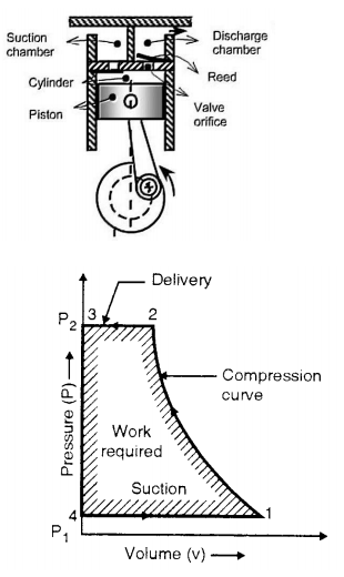
In single stage reciprocating air compressor, the entire compression is carried out in a single cylinder. The opening & closing of a simple check valve (plate or spring valve) depends upon the difference in pressure, if mechanically operated valves are used for suction & discharge then their functioning is controlled by cams. The weight of air in the cylinder will be zero when the piston is at top dead centre. At this position, you have to neglect clearance volume.
When piston starts moving downwards, the pressure inside the cylinder falls below atmospheric pressure& suction valve/inlet valve opens. The air is drawn into the cylinder through a suction filter element. This operation is known as suction stroke.
When the piston moves upwards, compresses the air in cylinder & inlet valve closes when the pressure reaches atmospheric pressure. Further compression follows as the piston moves towards the top of its stroke until when the pressure in the cylinder exceeds that in the receiver. This is compression stroke of a compressor. At the end of this stroke discharge/delivery valve opens & air is delivered to a receiver.
Advantages and disadvantages of reciprocating compressor
Advantages:
1. High thermal efficiency and low power consumption per unit
2. Convenient processing, low material requirements and low cost
3. Simple device system
4. Early design and production, mature manufacturing technology
5. Wide range of application
Disadvantages:
1. There are many moving parts, complex structure, heavy maintenance work and high maintenance cost
2. Speed Limited
3. The wear of piston ring, the wear of cylinder and the transmission mode of belt make the efficiency drop rapidly
4. Loud noise
5. The backward control system does not meet the needs of chain control and unattended, so although the price of piston machine is very low, it is often not accepted by users.
Applications:
The reciprocating compressor generally seen where there is requirement of high pressure and low flow (or discontinuous flow up to 30 bars). Mostly where the air is used for hand-tools, cleaning dust, small paint jobs, commercial uses, for examples-
1. In spray painting shop.
2. In workshop for cleaning machines.
3. For operation of pneumatic tool like rock drill, vibrator etc.
4. In automobile service station to clean vehicle.
5. To drive air motors in coal mines.
Rotary Air Compressor:
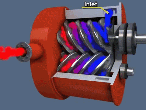
Rotary compressors are the type of famous compressors. It uses two Asymmetrical rotors that are also called helical screws to compress the air.
The rotors have a very special shape and they turn in opposite directions with very little clearance between them. The rotors are covered by cooling jackets. Two shafts on the rotors are placed that transfer their motion with the help of timing gears that are attached at the starting point of the shafts/compressor (as shown in the image).
Rotary Compressors and Types
Working principle-Air sucked in at one end and gets trapped between the rotors and get pushed to other side of the rotors. The air is pushed by the rotors that are rotating in opposite direction and compression is done when it gets trapped in clearance between the two rotors. Then it pushed towards pressure side.
Rotary screw compressors are of two types oil-injected and oil-free. Oil-injected is cheaper and most common than oil-free rotary screw compressors.
Advantages
i) Less noisy.
Ii) These are called the work-horses as they supply large amount of compress air.
Iii) More energy efficient as compared to piston type compressors.
Iv) The air supply is continuous as compared to reciprocating compressors.
v) Relatively low-end temperature of compressed air.
Rotary scroll compressor
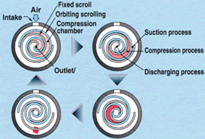
They are one of the best compressor types in rotary compressors. The air is compressed using two spiral elements. One element is stationary and the other one moves in small eccentric circles inside the spiral. Air gets trapped inside the spiral way of that element and get transported in small air-pockets to the centre of the spiral.
Simply air gets trapped at the outer edge and get compressed due to reduction of our as it travels from outer edge to inner edge. It takes about 2 to 3 turns for the air to reach the pressure output in the centre.
Vane Type Rotary Compressor
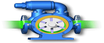
This is a type of rotary compressor. There is a fixed casing in Vane type compressor in which a rotary rotor disc is placed which has slots that are used for holding the sliding plates.
Whenever rotor rotates the disc also rotates thus allowing the sliding plates to slide as the inner surface of casing is eccentric. Whenever the plates move away from the centre a huge amount of air get trapped inside it and with the rotation the sliding plates converge due to its shape and the trapped air get compressed. This results in compression of air.
Lobe Type Air Compressor
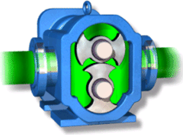
This is one of the simpler compressor types. In this there is no complicated moving part. There are two lobes attached to the driving shaft by the prime mover. These lobes are displaced with 90 degrees to one another. Thus, if one of the lobes is in horizontal direction the other lobes will be exactly positioned at 90 degree i.e. in vertical direction.
The air gets trapped from one end and as the lobes rotates the air gets compressed as shown in image. The compressed air is then delivered to delivery line.
Centrifugal Air Compressor
Centrifugal compressor is also termed as turbo compressors. In centrifugal compressors, energy will be supplied from outside and again energy will be imparted to the fluid by the machine and by virtue of which fluid will gain its internal energy and this internal energy will be gained by the fluid in the terms of rise in static pressure and in the terms of kinetic energy i.e. high flow velocity.
In centrifugal compressors, required rise in pressure will take place due to the continuous conversion of angular momentum imparted to the working fluid by a high-speed impeller in to static pressure. Centrifugal compressors are steady flow devices and hence they are subjected to less vibration and noise.
In centrifugal compressors, working fluid i.e. air will enter to the compressor at the impeller eye axially and will be released radially outward or we can say that compressed air will leave the compressor in radial direction.
Centrifugal compressor components
There will be basically three important components in a centrifugal compressor as mentioned below.
- Stationary casing
- Impeller or rotor of centrifugal compressor
- Diffuser
Casing
The casing of a centrifugal compressor will be approximately similar to the casing of a centrifugal pump. Casing is basically an air tight passage surrounding the impeller and will be designed in such a way that the kinetic energy of working fluid (let us say air) discharged at the outlet of the impeller will be converted in to pressure energy before the fluid leaves the casing and enters to delivery pipe.
Impeller or rotor of centrifugal compressor
Impeller, which is also termed as rotor of centrifugal compressor, is displayed here in following figure.
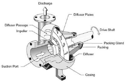
There will be one shaft of centrifugal compressor which will be coupled with the shaft of electric motor. Impeller or rotor of centrifugal compressor is basically a circular disc mounted over the compressor shaft with key assembly. Curved blades will be mounted on this circular disc. Number of these curved vanes will differ and it will be approximately 15 to 20 vanes in an impeller of a centrifugal compressor. These curved vanes, fixed over the impeller of a centrifugal compressor, will provide the diverging passage to the working fluid or air.
The centre of the impeller will be termed as impeller eye and air will be sucked at this impeller eye when impeller will be rotated and further air will move along the curved vanes of impeller in radial outward direction. When impeller will be rotated, the pressure energy of the air will be increasing as air will move in radial outward direction along the curved vanes of the impeller.
As impeller will be rotating, therefore a tangential velocity will be imparted on the fluid and hence fluid will secure a centripetal acceleration and it will be manifested in terms of the rise in pressure in radial outward direction.
Working fluid i.e. air will have high velocity and high pressure at the outlet of the impeller or at the tip of the impeller of the centrifugal compressor.
Diffuser
Diffuser is provided inside the casing. Impeller will be surrounded by a series of stationary guide vanes mounted on the diffuser ring as displayed here in following figure.
The purpose of diffuser is to convert the kinetic energy in to static pressure energy and we must note it here that a diffuser is very important part of a centrifugal compressor in order to secure the high productivity or performance.
Diffuser is basically provided in order to increase the pressure of working fluid i.e. air. Working fluid i.e. air will have high velocity and high pressure at the outlet of the impeller or at the tip of the impeller of the centrifugal compressor.
Centrifugal compressor operation tends to develop more pressure and hence air from the outlet of the impeller will enter and pass through some stationary curved vanes. These stationary curved vanes will be fixed over the diffuser.
These stationary curved guide vanes will provide a passage of diverging in nature and hence it increases the cross-sectional area in the direction of flow which will convert the kinetic energy in to pressure energy.
At the outlet of diffuser, air will be with very high static pressure and with relatively very lower velocity of flow. Therefore, air with high static pressure will flow to delivery pipe of centrifugal compressor from the outlet of diffuser of compressor.