UNIT-1
FRICTION AND MECHANICS OF SOLIDS
1.1.1 FRICTION
Pushing, lifting and pulling are contact forces that we experience in the everyday world. Rest your hand on a table; the atoms that form the molecules that make up the table and your hand are in contact with each other. If you press harder, the atoms are also pressed closer together. The electrons in the atoms begin to repel each other and your hand is pushed in the opposite direction by the table.
According to Newton’s Third Law, the force of your hand on the table is equal in magnitude and opposite in direction to the force of the table on your hand. Clearly, if you push harder the force increases. If you push your hand straight down on the table, the table pushes back in a direction perpendicular (normal) to the surface. Slide your hand gently forward along the surface of the table. You barely feel the table pushing upward, but you do feel the friction acting as a resistive force to the motion of your hand. This force acts tangential to the surface and opposite to the motion of your hand. Push downward and forward.
Try to estimate the magnitude of the force acting on your hand. The force of the table acting on your hand, , is called the contact force. This force has both a normal component to the surface,
  , called the normal force, and a tangential component to the surface,
  , called the frictional force(Figure 1).
|
Figure 1: Normal and tangential components of the contact force
By the law of vector decomposition for forces


 +
+ 
Any force can be decomposed into component vectors so the normal component,  , and the tangential component,
  , are not independent forces but the vector components of the contact force perpendicular and parallel to the surface of contact.
It is harder to move objects with larger inertia, but there are ways to make moving objects with larger amounts of inertia easier. One way is to reduce the amount of friction between the object and its contact surface.
Friction is a force that resists the relative motion of two objects in contact, caused by the irregularities of the surfaces coming into contact and colliding with each other.
If we slide or try to slide a body over a surface the motion is resisted by a bonding between the body and the surface. This resistance is represented by a single force and is called friction.
The force of friction is parallel to the surface and opposite to the direction of intended motion.
It is parallel to the contact surface between systems and always in a direction that opposes motion or attempted motion of the systems relative to each other.
If the two systems are in contact and moving relative to one another, then the friction between is called kinetic friction.
When objects are stationary, static friction can act between them.
The static friction is usually greater than the kinetic friction between the objects.
1.1.2 TYPES OF FRICTION
As mentioned above Friction is broadly is classified in two categories. These are
- Static Friction is the force that opposes the start of relative motion between two objects in contact with each other.
- Kinetic/Dynamic Friction is the force that opposes the relative motion between two objects in contact with each other when the objects are actually in motion.
Friction is the force that opposes motion between any surfaces that are in contact. There are Two types of friction: Static (limiting friction), Kinetic or dynamic friction (sliding, rolling and fluid friction). Static, sliding, and rolling friction occur between solid surfaces. Fluid friction occurs in liquids and gases. All these types of friction are described below.
- Static friction: The opposing force that comes into play when objects are at rest. Static Friction, Static friction acts on objects when they are resting on a surface. For example, if you are hiking in the woods, there is static friction between your shoes and the trail each time you put down your foot (see Figure 2 below). Without this static friction, your feet would slip out from under you, making it difficult to walk. In fact, that's exactly what happens if you try to walk on ice. That's because ice is very slippery and offers very little friction.
|
Figure 2: Static friction
Push your hand forward along a surface; as you increase your pushing force, the frictional force feels stronger and stronger. Try this! Your hand will at first stick until you push hard enough, then your hand slides forward. The magnitude of the static frictional force, fs, depends on how hard you push.
One example is the friction that helps the people climb the rock wall in the opening picture above. Static friction keeps their hands and feet from slipping.
(i) In this case static friction F = P.
(ii) Static friction is a self-adjusting force because it changes itself in accordance with the applied force.
|
Figure 3: Box on plane
Limiting friction: The maximum value of static friction up to which body does not move is called limiting friction.
(i) The magnitude of limiting friction between any two bodies in contact is directly proportional to the normal reaction between them.
F1 R or F1= usR
ii) Direction of the force of limiting friction is always opposite to the direction in which one body is at the verge of moving.
(iii) Coefficient of static friction:
(a) s is called coefficient of static friction.
(b) Dimension: [M0L0T0]
(c) Unit: It has no unit.
(d) Value of s lies in between 0 and 1
(e) Value of depends on material and nature of surfaces in contact.
(f) Value of does not depend upon apparent area of contact
2. Kinetic or dynamic friction: If the applied force sets the body in motion, the friction opposing the motion is called kinetic friction.
(i) Kinetic friction depends upon the normal reaction friction.
Fk  R or Fk = kR where k is called the coefficient of kinetic friction.
(ii) Kinetic friction is always lesser than limiting friction Fk < F1 k < s
Thus we require more force to start a motion than to maintain it against friction. This is because when motion has actually started, irregularities of one surface have little time to get locked again into the irregularities of the other surface.
Based on experimental measurements, the force of kinetic friction, Fk, between two surfaces, is independent of the relative speed of the surfaces, the area of contact, and only depends on the magnitude of the normal component of the contact force. The force law for the magnitude of the kinetic frictional force between the two surfaces can be modelled by Fk =μkN, where μk is called the coefficient of kinetic friction.
(iv) Types of kinetic friction:
(a) Sliding friction: Sliding friction is friction that acts on objects when they are sliding over a surface. Sliding friction is weaker than static friction. That's why it's easier to slide a piece of furniture over the floor after you start it moving than it is to get it moving in the first place. Sliding friction can be useful. For example, you use sliding friction when you write with a pencil. The pencil “lead” slides easily over the paper, but there's just enough friction between the pencil and paper to leave a mark. There is sliding friction between the brake pads and bike rims each time you use your bike's brakes. This friction slows the rolling wheels so you can stop.
(b) Rolling friction: Rolling friction is friction that acts on objects when they are rolling over a surface. Rolling friction is much weaker than sliding friction or static friction. This explains why most forms of ground transportation use wheels, including bicycles, cars, 4-wheelers, roller skates, scooters, and skateboards. Ball bearings are another use of rolling friction. You can see what they look like in the Figure below. They let parts of a wheel or other machine roll rather than slide over on another. The ball bearings in this wheel reduce friction between the inner and outer cylinders when they turn.[Figure 4].
|
Figure 4: Ball bearing in a wheel
Rolling friction is directly proportional to the normal reaction (R) and inversely proportional to the radius (r) of the rolling cylinder or whell.
FRrolling = r
|
is called coefficient of rolling friction. It would have the dimensions of length and would be measured in metre.
Rolling friction is often quite small as compared to the sliding friction. In rolling the surfaces at contact do not rub each other.
The velocity of point of contact with respect to the surface remains zero all the times.
(c) Fluid Friction: Fluid friction is friction that acts on objects that are moving through a fluid. A fluid is a substance that can flow and take the shape of its container. Fluids include liquids and gases. If you've ever tried to push your open hand through the water in a tub or pool, then you've experienced fluid friction. You can feel the resistance of the water against your hand. Look at the skydiver in the Figure below. He's falling toward Earth with a parachute. Resistance of the air against the parachute slows his descent. The faster or larger a moving object is, the greater is the fluid friction resisting its motion. That's why there is greater air resistance against the parachute than the skydiver's body.
|
Figure 5: Fluid Friction
1.1.3 LAWS OF FRICTION
The friction of the moving object is proportional and perpendicular to the normal force.
- Friction is always parallel to the contact surface and is in the opposite direction of the force causing the motion.
- The coefficient of static friction is greater than the coefficient of kinetic friction. This is due to inertia –An object at rest tends to stay at rest while an object in motion tends to continue moving.
- Friction increases as the force between two surfaces increases.
- Friction depends on the nature of the materials coming into contact with each other.
- Friction depends on the force pressing the objects together.
- Kinetic friction is independent of velocity.
- Friction is independent of the area of contact as long as there is an area of contact.
A surface can always supply a normal force, perpendicular to the surface. However, a surface quite often also supplies a fiction force parallel to the plane. Friction forces always oppose the motion -- or prevent the motion.
Let us take a example of pulling on a block to the right with an external force F as shown here:
|
Figure 6: Pulling on a block to the right with an external force
We know gravity pulls down with a force w, the weight of the block. From the y-components of F = ma, we have seen that the plane responds by exerting a normal force n . But the surface also responds by exerting a parallel force, fs; this is the force of static friction.
When we first push on this block it does not move; it is held in place by this force of static friction. No matter how smooth the surfaces of the block and the plane appear at first glance, if we look at them under a microscope, we find they are quite rough.
But there is some maximum value of this force of static friction. If we increase the external force F, the block finally breaks loose and starts to move to the right. Now the forces on it are as shown in this sketch:
|
Figure 7: F and Fk Force acting on block
The surface exerts a force of kinetic friction that is labelled fk. "kinetic" simply means "moving"; this is the friction force once the block is in motion. This force of kinetic friction is less than the maximum value of the force of static friction; that is
fk < fs
This behaviour can be summarized in the graph,
Graph between Applied Force and Force of Friction
(1) Part OA = static friction (Fs).
(2) At point A = limiting friction (F1).
(3) Beyond A, the force of friction is seen to decrease slightly.
The portion BC = kinetic friction (Fk).
(4) As the portion BC of the curve is parallel to x axis therefore kinetic
So we have observed from graph that friction does not change with the applied force.
|
Figure 8: Graph between Applied Force and Force of Friction
1.1.4 ANGLE OF FRICTION, ANGLE OF REPOSE
Angle of Friction
Angle of friction may be defined as the angle which the resultant limiting friction and normal reaction makes with the normal reaction.
Angle of friction is defined as the angle made by the resultant of normal reaction and frictional force with the normal reaction.
Consider a body lying on a horizontal surface. Let R be the normal reaction and Fc be the frictional force. If α is the angle made by the resultant of normal reaction and frictional force with the normal reaction, then, α is the angle of friction.
|
Figure 9: Angle of Friction
Here, tanα = tanα = tanα = ∴tanα=μ ……………..(1)
|
Therefore, coefficient of limiting friction is equal to the tangent of angle of friction.
Angle of Repose
Angle of repose is defines as the angle of an inclined plane, at which a body placed on it just begins to slide.
Place a body of mass m on an inclined plane. Increase the angle of inclined plane till the body just begins to slide. If θ is the angle of inclination at which the body just begins to slide, then θ is the angle of repose.
|
Figure 10: Angle of Repose
The weight mg of the body acts vertically downwards. Because of the angle of inclination, this weight can be resolved into two components; mgcosθ and mgsinθ as shown in fig. If the body just begins to slide, then mgsinθ =Fc ……………(2) 2. mgcosθ is equal to the normal reaction mgcosθ=R ……………(3) Dividing (2) by (3),
tanθ = tanθ = μ ___(2) Thus, coefficient of limiting friction is equal to the tangent of the angle of repose. Relation between Angle of Friction and Angle of Repose From (1) and (3), tanα =μ= tanθ tanα = tanθ α=θ Thus, angle of friction is equal to the angle of repose.
|
Key Takeaways
- The force of the table acting on your hand,
 , is called the contact force. This force has both a normal component to the surface,
  , called the normal force, and a tangential component to the surface,
  , called the frictional force
 - By the law of vector decomposition for forces


 +
+ 
- Friction is a force that resists the relative motion of two objects in contact, caused by the irregularities of the surfaces coming into contact and colliding with each other.
- The static friction is usually greater than the kinetic friction between the objects.
- There are Two types of friction: Static (limiting friction), Kinetic or dynamic friction (sliding, rolling and fluid friction). Static, sliding, and rolling friction occur between solid surfaces. Fluid friction occurs in liquids and gases.
- Types of kinetic friction: (a) Sliding friction, (b) Rolling friction, (c) Fluid Friction
- Friction is always parallel to the contact surface and is in the opposite direction of the force causing the motion.
- The coefficient of static friction is greater than the coefficient of kinetic friction. Friction increases as the force between two surfaces increases.
- Friction is independent of the area of contact as long as there is an area of contact.
- Angle of repose is defines as the angle of an inclined plane, at which a body placed on it just begins to slide.
- Coefficient of limiting friction is equal to the tangent of angle of friction. ∴tanα=μ
Imagine, for example, trying to slide a heavy crate across a concrete floor, you might push on the crate and not able to move it at all. This means that the static friction responds to what you do—it increases to be equal to and in the opposite direction of your push.
If you finally push hard enough, the crate seems to slip suddenly and starts to move. Now static friction changes to kinetic friction. Once in motion, it is easier to keep it in motion than it was to get it started, indicating that the kinetic frictional force is less than the static frictional force.
If you add mass to the crate, say by placing a box on top of it, you need to push even harder to get it started and also to keep it moving.
Furthermore, if you oiled the concrete you would find it easier to get the crate started and keep it going.
Figure 11 is a crude pictorial representation of how friction occurs at the interface between two objects. Close-up inspection of these surfaces shows them to be rough.
Thus, when you push to get an object moving, you must raise the object until it can skip along with just the tips of the surface hitting, breaking off the points, or both. A considerable force can be resisted by friction with no apparent motion. The harder the surfaces are pushed together (such as if another box is placed on the crate), the more force is needed to move them. Part of the friction is due to adhesive forces between the surface molecules of the two objects, which explain the dependence of friction on the nature of the substance. Once an object is moving there are fewer points of contacts, So less force is required to keep the object is moving.
At small but nonzero speeds, friction is nearly independent of speeds.
|
Figure 11: Friction occurs at the interface between two objects.
Frictional forces, such as f, always oppose motion or attempted motion between objects in contact. Friction arises in part because of the roughness of the surfaces in contact, as seen in the expanded view. For the object to move, it must rise to where the peaks of the top surface can skip along the bottom surface. Thus a force is required just to set the object in motion.Much of the friction is due to the attractive forces between the molecules making up the two objects, so that even perfectly smooth surface are not friction-free.
|
Figure 12: (a) Impending Motion (b) Object moves (c) Graph of the frictional force versus the applied force
The force of friction  between the block and the rough surface opposes the direction of the applied force
  .
.
The magnitude of the static friction balances that of the applied force. This is shown in the left side of the graph in Figure 12 (c).
Figure 12 (b) At some point, the magnitude of the applied force is greater than the force of kinetics friction, and the block moves to the right. This is shown in the right side of the graph in Figure 12 (c).
The graph of the frictional force versus the applied force; note that fs(max) >fk this mean that μs > μk.
Work done in sliding a body on horizontal planes
Consider a body of mass m resting on a rough horizontal surface.
|
Figure 13: Work done in sliding a body on horizontal planes
The various forces acting on the body are:
(i) Weight, W = mg, of the body acts vertically downward.
(ii) Normal reaction R of the surface on the body, which cts acts vertically upwards,
Since a body is at rest, therefore
R = mg.
Let F be the kinetic force of friction between the body and the horizontal surface. If the body moves through the distance, 's', then the work done against friction is given by
work = F x S
Since,
F/R = μk ⇒ F = μk R = μk Mg ....[From (i)]
Work done = F x S = μk MgS
Motion on inclined planes
A body placed on an incline is subjected to downward pull due to gravity. The downward motion along the incline is, therefore, natural tendency of the body, which is opposed by friction acting in the opposite direction against the component of gravity along the incline. Depending on the relative strengths of two opposite forces, the body remains at rest or starts moving along the incline.
The translational motion of a body on an incline is along its surface. There is no motion in the direction perpendicular to the incline surface. The force components in the direction perpendicular to the incline form a balanced force system.
Let us examine the free body diagram as superimposed on the body systems and shown in the figure. In the direction of incline i.e. x – axis, we have :
|
Figure 14: Motion on inclined planes
Motion on incline plane Motion of the block is opposed by static friction.
∑Fx =mgsinθ−FF=ma
where FF is the force of friction, which can be static friction, maximum static friction or kinetic friction.
In the y-direction,
∑Fy = N−mgcosθ = 0⇒ N=mgcosθ
Based on the angle of incline” θ”, there are following possibilities:
Case 1 : The friction is less than the maximum static friction and body is yet to start motion. Here, θ<tan−1(μs). In this case, friction is simply equal to component of gravity, parallel to the contact surface. Thus,
|
Figure 15: Motion on inclined planes
Motion on incline plane Motion of the block is opposed by static friction.
FF=fs=mgsinθ
The net component of external forces in x-direction (including friction), therefore, is zero. As such, the block remains stationary.
∑Fx = mgsinθ − FF= mgsinθ−mgsinθ = 0
Case 2: The friction is equal to the maximum static friction and body is yet to start motion. Here, θ=tan−1(μs). In this case also, the component of net external force in x-direction (inclusive of friction) is zero and the block is stationary. Here,
⇒tanθ = tanφ =μs
Case 3: The friction is equal to the kinetic friction and body is in motion. Initially, θ>tan−1(μs). In this case, friction is given by:
FF=Fk=μkN
We must understand here that friction can be equal to kinetic friction only when body has started moving. This is possible when component of gravity, parallel to contact surface is greater than the maximum static friction. However, once this condition is fulfilled, the friction between the surfaces reduces slightly to become equal to kinetic friction. Subsequently, the motion of the body can be either without acceleration (uniform velocity) or with acceleration.
Motion with uniform velocity
This is a case of balanced force system in x-direction. The component of net force in x-direction is zero and the block is moving with constant velocity. Here,
⇒tanθ=μk
Accelerated motion
This is a case of unbalanced force system in x-direction.
|
Figure 16: Accelerated motion
Motion on incline plane Motion of the block is opposed by kinetic friction.
In x – direction,
∑Fx= mgsinθ−FF = max ⇒ mgsinθ−μkN=ma
Putting value of normal force, N, we have:
⇒ mgsinθ−μkmgcosθ = ma ⇒a= gsinθ−μkgcosθ
For the given value of “θ” and “μk”, acceleration is constant and the block, therefore, moves down with uniform acceleration.
Example: A block of mass “m” slides down an incline, which makes an angle of 30° with the horizontal. If the acceleration of the block is g/3, then find the coefficient of kinetic friction. Consider g = 10 m/s2.
Solution:
The coefficient of kinetic friction is given by :
μk=FkN
In order to evaluate this ratio, we need to find normal and friction forces. The free body diagram of the block as superimposed on the system is shown in the figure 16.
|
Figure 17: Motion on inclined planes
Motion on incline plane Motion of the block is opposed by kinetic friction.
In the x-direction, ∑Fx = mgsin300−Fk =max ⇒ mgsin300− Fk =m ⇒mg ⇒Fk = mg In the y-direction, there is no acceleration, ∑Fy = mgcos300−N = 0⇒ N=mgcos300 = Putting values in the expression of coefficient of friction, we have: μk =
|
Key Takeaways
- Frictional forces, such as f, always oppose motion or attempted motion between objects in contact.
- For the object to move, it must rise to where the peaks of the top surface can skip along the bottom surface. Thus a force is required just to set the object in motion.
- The graph of the frictional force versus the applied force; note that fs(max) >fk this mean that μs > μk.
- Work done in sliding a body on horizontal planes F x S = μk MgS
- Motion on incline plane ⇒a= gsinθ − μkgcosθ, For the given value of “θ” and “μk”, acceleration is constant and the block, therefore, moves down with uniform acceleration.
First, let us find out why do we need to reduce friction?
Disadvantages of friction
- Unwanted heating effects like forest fires
- Unwanted noise pollution like highway road sounds
- Wear and tear most commonly seen in shoes
- Reduced efficiency in machines
- Slows down many processes
1) Friction can be reduced by making the surface smooth by polishing
The friction is due to the roughness of surface. If we make the surfaces smooth by polishing, then friction will be reduced. For example a slide in the park is polished to make its surface smooth and reduce friction. Due to reduced friction of a polished, smooth slide, children can slide down easily.
2) Friction can be reduced by applying lubricants (like oil or grease) to the rubbing surface
When oil or grease is applied between the moving parts of a machine, a thin layer of oil or grease is formed between the two rubbing surfaces. This layer of oil separates the two rubbing surfaces a little bit due to which their interlocking is reduced to a large extent. This friction is reduced and movement becomes smooth. When oil or grease is applied to the moving parts of a machine, then their surfaces do not rub directly against each other, they rub through a layer of oil and grease.
The substance which reduce friction are called lubricants Oil, grease, graphite and fine powder are lubricants. The applying of lubricants to a machine is called lubrication. Friction can be reduced by lubrication. A well lubricated machine runs more smoothly and lasts longer.
- A bicycle mechanic and motor mechanic uses grease between the moving parts of these machines to reduce friction and increase efficiency
- When a few drops of oil are poured on the hinges of a door, the friction is reduced and the door smoothly.
- We Sprinkle fine powder as dry lubricant on carrom board to reduce friction.
- In some machines an air cushion between the moving parts is used to reduce friction. For example, the frictional drag from the sea on hovercraft is reduced by a cushion of compressed air. (A vehicle or craft which travels over land or water on a cushion of air provided by a downward blast is called hovercraft)
3) Friction can be reduced by using wheels to move objects
It is quite difficult to move a heavy suitcase by dragging it on the ground because the sliding friction between the heavy suitcase and the ground is very large. If this heavy suitcase is fitted with small wheels then it can be pulled very easily. Because when we attach wheels then sliding friction is converted into rolling friction. And rolling friction between the wheels of suitcase and ground is much less.
Friction can be reduced by attaching wheels to move the objects.
4) Friction can be reduced by using ball bearing between the moving parts of machine
Ball bearing is a device which consists of a ring of small metal balls. The small metal balls of a ball bearing can roll freely. They are designed to make the moving parts of a machine to roll over each other rather than slide. The ball bearing is introduced between the two surfaces which have to rotate over each other. The axle is fixed on the inner side of a ball bearing and wheel is fixed to the outer side of the ball bearing the ball bearing. They reduces friction by making the two surfaces (axle and wheel) to roll over each other. This happens due to the rolling action of small metal balls present inside the ball bearing.
Even a wheel produces some friction where its central hole rubs with the axle. To reduce friction still further, wheels are mounted on ball bearing. The ball bearing is fixed between the hub of wheel and axle. When the wheel revolves the balls of ball bearing roll and reduce friction. The use of ball bearing makes the wheel roll smoothly over the axle. In most of the machine friction is reduced by using ball bearing. The Wheels of the bicycle turn on sets of ball bearing. These ball bearings reduce friction because they roll rather than slide.
5. Streamlined design of the sliding body
A streamlined body helps in reducing friction especially in fluids. It enables the sliding body to easily pass through the medium with the least resistance. The streamlined body of fishes and birds are mimicked to ensure minimal friction. Streamlined body of bullet trains.
|
Figure 18: Bullet Trains
6. Reduce contact between surfaces
Reducing contact during sliding can reduce friction. we can reduce contact by magnetic levitation or by charging both the surfaces with same polarity. Maglev (Magnetic levitation) trains run on the principle of magnetic levitation to reduce friction in order to increase speed and travel experience.
|
Figure 19: Reduce contact between surfaces
7. Convert to rolling friction
Sliding friction is always greater than rolling friction. Imagine a car with square wheels. Rolling friction is applied widely in our daily lives.
Examples in our daily lives: Ball bearings use balls to separate two bearing races. Hence sliding friction is converted into rolling friction. The races won’t slide over each other now but transfer the load to the balls through rolling friction.
|
Figure 20: Ball bearings
8. Reduce pressure or weight on the object
Friction is directly proportional to normal force applied on it. Since we are on earth, the weight of the body is the normal force on the object generally. In space there will be very less or no friction. So, choose materials wisely to reduce the friction.
9. Use fluid friction instead of the dry friction
Fluids offer less friction compared to solid surfaces. That is why aircraft can travel at high speeds compared to cars. Also, when we are applying lubricants or oil onto surfaces, we are essentially converting dry friction into fluid friction.
APPLICATIONS OF FRICTION
- Friction plays an important part in many everyday processes. For instance, when two objects rub together, friction causes some of the energy of motion to be converted into heat. This is why rubbing two sticks together will eventually produce a fire.
- Friction is also responsible for the wear and tear on bike gears and other mechanical parts. That's why lubricants, or liquids, are often used to reduce the friction — and wear and tear — between moving parts.
- Motion of pistons in a cylinder is an application of friction.
- It is possible to write on books and board as there is friction between pen and the board.
- Sticky pads are used to prevent object from slipping off smooth surfaces by effectively increasing the friction coefficient between the surface and the object.
- Automobile brakes inherently rely on friction, slowing a vehicle by converting its kinetic energy into heat. Dealing with dispersing this large amount of heat safely is one technical challenge in designing brake systems.
- Disk brakes rely on friction between a disc and brake pads that are squeezed transversely against the rotating disc.
Key Takeaways
- Friction can be reduced by making the surface smooth by polishing
- Friction can be reduced by applying lubricants (like oil or grease) to the rubbing surface
- Friction can be reduced by using wheels to move objects
- Friction can be reduced by using ball bearing between the moving parts of machine
- Streamlined design of the sliding body
- Reduce contact between surfaces
- Convert to rolling friction
- Reduce pressure or weight on the object
- Use fluid friction instead of the dry friction
Deformation is the change in shape of the body when a force is applied on it. Even very small magnitude of forces is enough to cause some deformation.
Two terms describe the forces on objects undergoing deformation:
- Stress
- Strain
STRESS
When an external force is acting on an elastic body, it causes deformation that means change in shape or in size or both.
Stress = Force/Area = F/A
The stress is defined as the restoring force acting on unit area.
Unit: The unit for stress is Newton Metre-2 or Nm-2 or Pascal written as Pa.
Restoring Force: Due to elastic property, a force is developed within the material, which is equal and opposite to the applied force, this force is responsible to bring the body to its original shape and size. This force is Restoring Force.
Since the applied force and the restoring force are equal in magnitude, the ‘stress’ is measured as the applied force acting per unit area.
- When the applied force tends to compress the body, the stress is compressive stress.
- When it tends to increase the length in the direction of the force, it is tensile stress.
- When it acts parallel to the surface of a body, the stress is tangential stress or Shear stress.
- When an object is being squeezed from all sides, like a submarine in the depths of an ocean, we call this kind of stress a bulk stress or volume stress.
STRAIN
Within the elastic limits, the strain produced in a body is directly proportional to the stress which causes it.
i.e. strain ∝ stress or stress ∝ strain
Strain: Change in dimensions to original dimensions is known as Strain.
Types of Strain
(1) Linear Strain: When a wire or bar is subjected to two equal and opposite forces namely pulls at its ends there is an increase in the length. If the forces are tensile, the body is elongated. If the forces are compressive, the length is shortened in the direction of the forces. This is called the 'linear strain'.
The linear strain is defined as the ratio of change in length to the original length.
If the change (increase or decrease) in length is ' 5m ' in a wire or bar of original length L=20m.
Linear strain = Change in length/ original length = 5m/20m = 0.25
As the linear strain is ratio of lengths, it has no unit.
(2) Bulk (or) Volume Strain: When a force is applied uniformly and normally to the entire surface of the body, there is a change in volume of the body, without any change in its shape. This strain is called 'bulk or volume strain.
Volume strain is defined as the ratio of change in volume to the original volume.
If 'v' is the change in volume produced in a body of original volume ‘V’
Bulk or volume strain = Change in volume v / original volume V
It has also no unit.
(3) Shearing (or) Rigidity strain: When a force is applied parallel to one face of a body, the opposite side being fixed, there is a change in shape but not in size of the body. This strain is called the shearing strain.
Solids alone can have a shearing strain. It is measured by the angle of the shear 'θ' in radian.
Key Takeaways
- Even very small magnitude of forces is enough to cause some deformation
- The stress is defined as the restoring force acting on unit area.
- Stress can be compressive stress, tensile stress, tangential stress and bulk stress.
- Change in dimensions to original dimensions is known as Strain.
- Strain can be linear, Bulk and rigidity strain.
ELASTIC BEHAVIOR OF SOLIDS
The property of matter by virtue of which its regains its original shape and size, when deforming forces have been removed is called elasticity.
An elastic body is one that regains its original shape and size when deforming forces are removed.
To know more about elasticity let us look at atomic level. We know that solids are made of atoms (or molecules). They are surrounded by other such atoms which are held by interatomic forces in a state of equilibrium. When an external force is applied these particles are displaced, resulting in the deformation of the solid. When the applied force is removed interatomic forces drive the atoms to regain their state of equilibrium.
In reality no material is perfectly elastic. For example, if you use a hair rubber band to tie your hair, you will found that rubber band loose its elasticity after some time. If you may have noticed that even your hair shows deformation from its original shape, when it is put in certain style for long time that is its size tends to deform after prolonged use. This is because the hair tie eventually loses its elastic nature.
Most solid materials exhibit elastic behaviour to a greater or lesser extent. But there is a limit to the magnitude of the force and the associated deformation within which elastic recovery is possible for any given material. This limit is called the elastic limit. It is defined as the maximum stress or force per unit area within a solid material that can arise before the beginning of permanent deformation.
For such materials the elastic limit marks the end of elastic behaviour and the beginning of plastic behaviour.
Stress beyond the elastic limit cause a material to yield or flow.
For most brittle materials, stresses beyond the elastic limit result in fracture with almost no plastic deformation.
Different materials show different elastic behaviour. The study of the elastic behaviour of a material is of much importance. Almost every engineering design requires knowledge of the elastic behaviour of materials.
Unlike fluids, solids do not respond to outside force by flowing or easily compressing. The term elasticity refers to the manner in which solids respond to stress, or the application of force over a given unit area. An understanding of elasticity—a concept that helps to illuminate the properties of objects from steel bars to rubber bands to human bones.
Elasticity, ability of a deformed material body to return to its original shape and size when the forces causing the deformation are removed. A body with this ability is said to behave (or respond) elastically.
Most solid materials exhibit elastic behaviour to a greater or lesser extent, but there is a limit to the magnitude of the force and the accompanying deformation within which elastic recovery is possible for any given material. This limit, called the elastic limit.
Elastic limit is the maximum stress or force per unit area within a solid material that can arise before the onset of permanent deformation. Stresses beyond the elastic limit cause a material to yield or flow.
For these type of materials the elastic limit tells the end of elastic behaviour and the beginning of plastic behaviour.
But for some brittle materials, stresses beyond the elastic limit result in fracture. No plastic deformation exists in these types of cases.
Metals and Elasticity
Metals, in fact, exhibit a number of interesting characteristics with regard to elasticity. With the notable exception of cast iron, metals tend to possess a high degree of ductility, or the ability to be deformed beyond their elastic limits without experiencing rupture. Up to a certain point, the ratio of tension to elongation for metals is high: in other words, a high amount of tension produces only a small amount of elongation. Beyond the elastic limit, however, the ratio is much lower: that is, a relatively small amount of tension produces a high degree of elongation.
For example, a steel bar or wire can be extended elastically only about 1 percent of its original length, while for strips of certain rubber like materials, elastic extensions of up to 1,000 percent can be achieved. Thus elastic limit depends on the type of solid considered.
Steel is much stronger than rubber, however, because the tensile force required to effect the maximum elastic extension in rubber is less (by a factor of about 0.01) than that required for steel. The elastic properties of many solids in tension lie between these two extremes.
The different macroscopic elastic properties of steel and rubber are because of the different microscopic structures.
Here is the point to note that the elasticity of steel and other metals arises from short-range interatomic forces that, when the material is unstressed, maintain the atoms in regular patterns. Under stress the atomic bonding can be broken at quite small deformations.
Whereas at the microscopic level, rubber like materials and other polymers consist of long-chain molecules that uncoil as the material is extended and recoil in elastic recovery.
The mathematical theory of elasticity and its application to engineering mechanics is concerned with the macroscopic response of the material and not with the underlying mechanism that causes it.
The elastic limit is in principle different from the proportional limit, which marks the end of the kind of elastic behaviour that can be described by Hooke’s law, namely, that in which the stress is proportional to the strain (relative deformation) or equivalently that in which the load is proportional to the displacement. The elastic limit nearly coincides with the proportional limit for some elastic materials, so that at times the two are not distinguished; whereas for other materials a region of non-proportional elasticity exists between the two.
Gases and liquids also possess elastic properties since their volume changes under the action of pressure. For small volume changes, the bulk modulus, κ, of a gas, liquid, or solid is defined by the equation P = −κ(V − V0)/V0, where P is the pressure that reduces the volume V0 of a fixed mass of material to V. Since gases can in general be compressed more easily than liquids or solids, the value of κ for a gas is very much less than that for a liquid or solid. By contrast with solids, fluids cannot support shearing stresses and have zero Young’s modulus.
The tensile strength in bone fibers comes from the protein collagen, while the compressive strength is largely due to the presence of inorganic (non-living) salt crystals. It may be hard to believe, but bone actually has an ultimate strength, both in tension and compression, greater than that of concrete.
The ultimate strength of most materials is rendered in factors of 108 N/m2—that is, 100,000,000 newtons (the metric unit of force) per square meter. For concrete under tensile stress, the ultimate strength is 0.02, whereas for bone, it is 1.3. Under compressive stress, the values are 0.2 and 1.7, respectively. In fact, the ultimate tensile strength of bone is close to that of cast iron (1.7), though the ultimate compressive strength of cast iron (5.5) is much higher than for bone.
It may be hard to understand how bone can be stronger than concrete, but that is largely because the volume of concrete used in most situations is much greater than the volume of any bone in the body of a human being. By way of explanation, consider a piece of concrete no bigger than a typical bone: under relatively small amounts of stress, it would crumble.
FACTORS AFFECTING ELASTICITY
It is found that bodies lose their elastic limit, due to elastic fatigue. Therefore, the manufacture should choose the material in such a way that it should regain its elastic property even when it is subjected to large number of cycles of stress.
For example substances like quartz, phosphor, bronze etc. May be employed in manufacturing of galvanometers, electrometers etc. after knowing their elastic properties.
Apart from elastic fatigue some material will have change in their elastic property because of the following factors.
- Effect of stress
- Effect of annealing
- Hammering and Rolling
- temperature
- Effect of impurities
- Effect of nature of crystals
- Effect of stress
When a material is subjected to a large number of cycles of stresses, it loses its elastic property even within elastic limit, it results in the formation of large crystal grain, which reduces the elastic property of the material. Taking these into account, the working stress on an engineering piece is kept far below its ultimate tensile strength. Therefore the working stress on the material should be kept lower than the ultimate tensile strengthen and the safety factor.
2. Effect of Annealing
Annealing is a process by which the material is heated to a very high temperature and then it is slowly cooled. Usually this process is adopted for the material to increase the softness and ductility in the material. But if annealing is made to a material it results in the formation of large crystal grains, which ultimately reduces the elastic property of the material.
3. Hammering and rolling
Crystal grains break up into smaller units by Hammering and rolling. This results in increase in elasticity of material.
4. Effect of temperature
Intermolecular forces decrease with increase in temperature so The elastic property of the materials decreases with the rise in temperature. Normally the elasticity increases with the decrease in temperature and vice-versa.
Examples
1. Lead is not a good elastic material. But at low temperature it becomes a very good elastic material. The elastic property of lead increases when the temperature is decreased.
2. A carbon filament which is highly elastic at normal temperature becomes plastic when it is at high temperature
3. Invar is a special alloy used for making pendulums and its elasticity is not affected by the temperature change in the normal temperature range.
5. Effect of impurities
The addition of impurities produces variation in the elastic property of the materials. The increase and decrease of elasticity depends upon the type of impurity added to it.
Examples:
1. When potassium is added to gold, the elastic property of gold increases.
2. When carbon is added to molten iron, the elastic property of iron decreases provided the carbon content should be more than 1% in iron.
6. Effect of nature of crystals
The elasticity also depends upon the types of the crystals, whether it is a single crystal or poly crystals. For a single crystal the elasticity is more and for a poly crystal the elasticity is less.
Key Takeaways
- The property of matter by virtue of which its regains its original shape and size, when deforming forces have been removed is called elasticity.
- In reality no material is perfectly elastic.
- For most brittle materials, stresses beyond the elastic limit result in fracture with almost no plastic deformation.
- Gases and liquids also possess elastic properties since their volume changes under the action of pressure.
- Some material will have change in their elastic property because of the certain factors Effect of stress, Effect of annealing, Hammering and Rolling, Temperature. Effect of impurities, Effect of nature of crystals.
The property of the material by virtue of which it does not regain its original shape when the external force acting on it is removed. It is called plasticity.
Plasticity.
It is also known as plastic deformation, is the ability of a solid material to undergo permanent deformation.
Under the effect applied forces a non-reversible change of shape is occur.
The transition from elastic behaviour to plastic behaviour is known as yielding.
Paraffin wax, wet clay are the nearest approach to a perfectly plastic bodies.
The solid acquires a permanent change in its structure if, on restoring the external environment (under which the deformation process has taken place) to the initial configuration, the solid fails to restore to the initial structure. The quantifiers for such structural changes can be the shape of the body (at a macroscopic level of observation) or a rearrangement of defects (at a microscopic level of observation).Unlike elasticity, plasticity is fundamentally a microscopic phenomenon.
To illustrate the phenomenon of plasticity we consider a simple example of stretching a metal wire (with cylindrical cross-section) under an isothermal environment. A representative element of the wire is selected and the following two quantities are measured:
- The force per unit cross-sectional area (stress) and
- The change in length of the element with respect to some fixed reference state (strain).
Below a certain critical value of stress and strain, the element under observation returns to its original state of stress and strain upon removal of the external mechanism for stretching. The collection of all such stress/strain values forms the elastic range associated with the material. The deformation remains elastic as long as the stress/strain values are restricted to the elastic range. For values beyond the elastic range, the element will undergo permanent structural changes. The boundary of the elastic range signifies the onset of plastic deformation and therefore can be appropriately termed as the yield limit for the transition from an elastic to a plastic deformation process. It should however be noted that for most materials an accurate measurement of the yield limit is difficult because of the gradual nature of the transition from elastic to plastic behaviour. It then becomes a matter of convention to choose an appropriate yield limit for such materials. Based on the nature of the yield limit, we distinguish between two models of plastic flow. The first model is known as perfect plasticity (or the ideal plastic flow), wherein the yield limit for stress is assumed to remain constant. The second model, however, allows the yield stress to vary with the structural changes in the body
Note from that for a zero strain, the stress does not necessarily vanish. This can be attributed to the presence of microstructure in the form of defects in the unstrained state, which induces internal stresses so as to maintain an equilibrium configuration of defects in the element.
Plasticity, ability of certain solids to flow or to change shape permanently when subjected to stresses of intermediate magnitude between those producing temporary deformation, or elastic behaviour, and those causing failure of the material, or rupture (see yield point).
Plasticity enables a solid under the action of external forces to undergo permanent deformation without rupture. Elasticity, in comparison, enables a solid to return to its original shape after the load is removed.
Plastic deformation occurs in many metal-forming processes (rolling, pressing, forging) and in geologic processes (rock folding and rock flow within the earth under extremely high pressures and at elevated temperatures).
Plastic deformation is a property of ductile and malleable solids. Brittle materials, such as cast iron, cannot be plastically deformed, though at elevated temperatures some, such as glass, which is not a crystallized solid, do undergo plastic flow.
Key Takeaways
- The property of the material by virtue of which it does not regain its original shape when the external force acting on it is removed. It is called plasticity.
- It is also known as plastic deformation, is the ability of a solid material to undergo permanent deformation.
- Zero strain, the stress does not necessarily vanish.
- Plastic deformation occurs in many metal-forming processes (rolling, pressing, forging) and in geologic processes
Strain Hardening
Figure 21: Stress Strain Curve
Stain Softening
Strain softening is defined as the region in which the stress in the material is decreasing with an increase in strain. This can be observed in certain materials after yielding point. It causes deterioration of material strength with increasing strain, which is a phenomenon typically observed in damaged quasi brittle materials, including fibre reinforced composites and concrete. It is primarily a consequence of brittleness and heterogeneity of the material.
Strain Softening Materials can also strain soften, for example soils. In this case, the stress-strain curve “turns down” as shown in figure. The yield surface for such a material will in general decrease in size with further straining.
|
Figure 22: uniaxial stress-strain curve for a strain-softening material
Key Takeaways
- Strain hardening (also called work-hardening or cold-working) is the process of making a metal harder and stronger through plastic deformation.
- A material that does not show any strain hardening (n=0) is classed as perfectly plastic.
- Strain softening is defined as the region in which the stress in the material is decreasing with an increase in strain. This can be observed in certain materials after yielding point.
1.8 FAILURE (FRACTURE/FATIGUE)
Figure 23: Fracture
Key Takeaways
- Fracture is the separation of an object or material into two or more pieces under the action of stress.
- Fracture strength, also known as breaking strength, is the stress at which a specimen fails via fracture.
- Bones, on the whole, do not fracture due to tension or compression. Rather they generally fracture due to sideways impact or bending.
In 17ᵗʰ century physicist Robert Hooke observed that the stress vs strain curve for many materials has a linear region.
Hooke's law: Within the elastic limits, the strain produced in a body is directly proportional to the stress which causes it.
i.e., strain ∝ stress or stress ∝ strain
So
|
This constant is called 'modulus of elasticity.
Hooks law can be defined as
The force required to stretch an elastic object such as a metal spring is directly proportional to the extension of the spring. This is known as Hooke's law and commonly written:
F=−kx
Where F is the force,
x is the length of extension/compression
k is a constant of proportionality known as the spring constant which is usually given in N/m.
Negative sign signify that the restoring force due to the spring is in the opposite direction to the force which caused the displacement.
Dimensional Formula [ML-1T-2]
The total length L of a spring under extension is equal to the nominal length L0 plus the extension x, L=L0+x and during compression of spring, it is given by L=L0 – x.
In a simple tension test, the elastic response of materials such as steel and bone is given by a linear relationship between the tensile stress σ, and the extension ratio, e.
σ = tension or stretching force per unit area of cross section of the material
e = difference between extended and initial lengths divided by the initial length
σ = Ee
where E, the constant of proportionality, is called Young’s modulus.
In other words, σ is proportional to e; this is expressed. The value of E depends on the material; the ratio of its values for steel and rubber is about 100,000.
The equation σ = Ee is known as Hooke’s law and is an example of a constitutive law.
It expresses, in terms of macroscopic quantities, something about the nature (or constitution) of the material. Hooke’s law applies essentially to one-dimensional deformations, but it can be extended to more general (three-dimensional) deformations by the introduction of linearly related stresses and strains (generalizations of σ and e) that account for shearing, twisting, and volume changes. The resulting generalized Hooke’s law, upon which the linear theory of elasticity is based, provides a good description of the elastic properties of all materials, provided that the deformations correspond to extensions not exceeding about 5 percent. This theory is commonly applied in the analysis of engineering structures and of seismic disturbances.
It was Hooke's observation that for linearly-elastic, isotropic materials, normal strain is proportional to normal stress with Young's modulus or the elastic modulus, E, as the constant of proportionality. For a stress along the x direction
And Poisson observed that an extension along x is accompanied by contractions in the orthogonal directions y and z.
where Poisson's ratio is the constant of proportionality. If a normal stress in the y direction is added to this, it would cause an extension in the y direction and proportional contractions in the x and z directions. For small deformation we can superpose the results.
Adding a third stress component in the z direction and rearranging terms gives generalized Hooke’s law for the normal components of stress and strain.
The shear strains are uncoupled from the normal strains and from each other for an isotropic material.
Here G is the shear modulus for the material, but only two elastic constants are needed to characterize an isotropic elastic material. Thus the shear modulus can expressed in terms of E and G can be eliminated.
In the three-dimensional case there are six stress and six strain components. Referenced to a Cartesian coordinate system, x, y, z, the stress and strain vectors are written as follows. The relationships between strain and stress can be written as
where C is the compliance matrix of elastic constants relating strain and stress. Using the notations above.
The inverse of this relationship is also of interest, that is, stresses written in terms of strains. Symbolically
where E = C-1 is a matrix of elastic constants relating stresses to strains. Inverting the compliance relation gives the stress-strain relation for an isotropic material with six stress and strain components as follows.
There are three significant sub-cases of the overall 3D stress/strain state that happen often sufficient to be recognised. These are a state of plane stress, a state of plane strain, and a case involving axisymmetric geometry and loading which causes axisymmetric stresses and strains. Some simplification of the generalized Hooke's laws can be realized in each case.
|
Plane Stress
In a case of plane stress, one direction can be found that is free of normal stress and shear stress. If we place the z-axis in this direction, we must
The generalized Hooke's law equation reduces to
|
Plane Strain
In this case we have a direction along which the extensional strain is zero, and selecting the z axis as that direction, we have E z = 0, and the extensional stress-strain relations may be combined as follows.
|
Generalized Hooke's Law:
The general Hooke's Law can be used to expect the deformations produced in a specified material by an arbitrary grouping of stresses.
Figure 24: Hooke's Law
it's Young's modulus n is the Poisson ratio |
Generalized Hooke's law also reveals that tension can exist without stress. For example, if the member is experiencing a load in the y direction (which in turn causes stress in the y direction), Hooke's Law shows that the stress in the x direction is not equal to zero. This is because when the material is pulled out through the y plane, the material in the x plane moves inward to fill the void once occupied, just like an elastic band becomes thinner when you try to separate it. In this situation, the x plane does not have external forces that act on them, but undergo a change in length. Therefore, it is valid to say that voltage exists without voltage on the x plane.
Key Takeaways
|
A stress-strain curve is a graphical representation of the behaviour of a material when it's subjected to a load or force.
The two characteristics stress and strain are plotted. Stress along the y-axis and strain along the x-axis.
We already discussed that Stress is the ratio of the load or force to the cross-sectional area of the material. The standard unit of measurement for stress is Nm2.
Strain, on the other hand, is a measure of the deformation of the material as a result of the applied force. Deformation is a change in the shape of the material.
The stress-strain graph provides engineers and designers a graphical measure of the strength and elasticity of a material. It allows them to predict the behaviour of materials used in a given application. To draw the graph, the material must first undergo a tensile test.
|
Figure 25: Stress Strain Curve
When a ductile material consider a wire is put under stress, initially the resulting strain is proportional to the magnitude of the forces.
This is represented by the straight-line OA. The straight-line implies that stress and strain share a linear or we can simply say that the material obeys Hooke’s law. Stress corresponding to point A is known as proportionality limit. In this region, the material behaves like elastic.
Now when the stress is increased beyond A then for small stress there is large strain in the wire. Beyond the point A, stress and strain stop to share their linear relationship. The material in this region doesn’t obey Hooke’s law this fact can easily observe from its non-linear shape.
Still, even though the material doesn’t obey Hooke’s Law, it manages to retain its elasticity.
Point B is therefore known as the elastic point or elastic limit. Elastic limit represents the maximum stress on whose removal, the body regains its original shape or dimensions. This region OB is called the elasticity region.
Point B is also known as yield point because if the stress is increased beyond point B, the strain increases and increased in strain is represented by BC part of curve. Now if the load is removed the wire does not regain its original shape. But the increase in length is permanent. This permanent strain in the wire is known as permanent set.
Now further when the stress is increased beyond point C, there is large increase in the stain for small stress is represented by CD part of the curve.
The material from C to D shows plastic behaviour or plastic deformation.
The stress decreases until point C, which is known as the lower-yield point but as we can observe the material continues to elongate.
When plasticity is induced in the material its internal molecular structure suffers constant rearrangements. The material tries to resist this change and tends to harden. This is known as strain hardening.
However as the stress applied to it increases, it continues to elongate along its length, progressively growing longer and thinner until point D, which represents the material’s maximum strength. This is referred to as the material’s ultimate strength point.
Stress greater than D is so unbearable, beyond this wire break. The wire break at point E is known as fracture point.
Uses of stress-strain diagram
1. It is used to categorize the materials into ductile or brittle or plastic in nature.
2. It provides engineers and designers a graphical measure of the strength and elasticity of the material.
Idealization of One dimensional Stress-Strain Curve:
|
Figure 26: Idealization of One dimensional Stress-Strain Curve
Key Takeaways
- A stress-strain curve is a graphical representation of the behaviour of a material when it's subjected to a load or force.
- Stress is the ratio of the load or force to the cross-sectional area of the material. The standard unit of measurement for stress is Nm2.
- Strain, on the other hand, is a measure of the deformation of the material as a result of the applied force.
- It is used to categorize the materials into ductile or brittle or plastic in nature.
- It provides engineers and designers a graphical measure of the strength and elasticity of the material.
1.11.1 FORCE ANALYSIS - AXIAL FORCE, SHEAR FORCE, BENDING MOMENT
Shear force: The cutting force is the force on the radius that acts perpendicularly to its longitudinal axis (x). For design purposes, the ability of the beam to resist shear force is more important than its ability to resist axial force.
Axial force
it is the force in the radius that acts parallel to the longitudinal axis.
Below is a drawing of a simply supported beam of length L under uniform load, q:
|
Figure 27: Axial force
This beam has the following support reactions:
|
Figure 28: Beam
where Rl and R rare the responses at the left and right ends of the beam, correspondingly.
The shear forces at the ends of the beam are equivalent to the vertical forces of the support responses. The shear force F(x) at some other point x on the beam can be establish by using the succeeding equation.
|
here x is the distance from the left side of the beam.
Shear force diagrams are only plots of the shear force (on the y-axis) versus the position of various points along the beam (on the x-axis). Thus, the succeeding is the generalized shear force diagram for the beam shown above.
|
Figure 29: Shear force diagrams
Concept of Shear Force and Bending moment in beams: When the beam is loaded in some arbitrarily manner, the internal forces and moments are developed and the terms shear force and bending moments come into pictures which are helpful to analyze the beams further.
When a beam or frame is subjected to transverse loadings, the three possible internal forces that are developed are the normal or axial force, the shearing force, and the bending moment, as shown in section k of the cantilever of Figure 30. To predict the behaviour of structures, the magnitudes of these forces must be known.
|
Figure 30: The shearing force, and the bending moment,
- Normal Force
The normal force at any section of a structure is defined as the algebraic sum of the axial forces acting on either side of the section.
2. Shearing Force
The shearing force (SF) is defined as the algebraic sum of all the transverse forces acting on either side of the section of a beam or a frame. The phrase “on either side” is important, as it implies that at any particular instance the shearing force can be obtained by summing up the transverse forces on the left side of the section or on the right side of the section.
3. Bending Moment
The bending moment (BM) is defined as the algebraic sum of all the forces’ moments acting on either side of the section of a beam or a frame.
4. Shearing Force Diagram
This is a graphical representation of the variation of the shearing force on a portion or the entire length of a beam or frame. As a convention, the shearing force diagram can be drawn above or below the x-centroidal axis of the structure, but it must be indicated if it is a positive or negative shear force.
5. Bending Moment Diagram
This is a graphical representation of the variation of the bending moment on a segment or the entire length of a beam or frame. As a convention, the positive bending moments are drawn above the x-centroidal axis of the structure, while the negative bending moments are drawn below the axis.
Sign Convention
- Axial Force
An axial force is regarded as positive if it tends to tier the member at the section under consideration. Such a force is regarded as tensile, while the member is said to be subjected to axial tension. On the other hand, an axial force is considered negative if it tends to crush the member at the section being considered. Such force is regarded as compressive, while the member is said to be in axial compression (see Figure 31(a) and Figure 31(b).
2. Shear Force
A shear force that tends to move the left of the section upward or the right side of the section downward will be regarded as positive. Similarly, a shear force that has the tendency to move the left side of the section downward or the right side upward will be considered a negative shear force (see Figure 31c and Figure 31d).
3. Bending Moment
A bending moment is considered positive if it tends to cause concavity upward (sagging). If the bending moment tends to cause concavity downward (hogging), it will be considered a negative bending moment (see Figure 31e and Figure 31f).
|
Figure 31: Sign conventions for axial force, shearing force, and bending moment
Relation Among Distributed Load, Shearing Force, and Bending Moment
For the derivation of the relations among w, V, and M, consider a simply supported beam subjected to a uniformly distributed load throughout its length, as shown in Figure 32. Let the shear force and bending moment at a section located at a distance of x from the left support be V and M, respectively, and at a section x + dx be V + dV and M + dM, respectively. The total load acting through the center of the infinitesimal length is wdx.
|
Figure 32: Simply supported beam
To compute the bending moment at section x + dx, use the following:
Or Equation (1) implies that the first derivative of the bending moment with respect to the distance is equal to the shearing force. The equation also suggests that the slope of the moment diagram at a particular point is equal to the shear force at that same point. Equation (1) suggests the following expression:
Equation (2) states that the change in moment equals the area under the shear diagram. Similarly, the shearing force at section x + dx is as follows: Vx+dx = V – wdx V + dV = V – wdx or
Equation (3) implies that the first derivative of the shearing force with respect to the distance is equal to the intensity of the distributed load. Equation (3) suggests the following expression:
Equation (4) states that the change in the shear force is equal to the area under the load diagram. Equation (1) and (3) suggest the following:
Equation (5) implies that the second derivative of the bending moment with respect to the distance is equal to the intensity of the distributed load.
|
Conclusions:
|
1.11.2 TWISTING MOMENT
Consider a cylindrical rod of length l radius r and coefficient of rigidity η. Its upper end is fixed and a couple is applied in a plane perpendicular to its length at lower end as shown in figure.
|
Figure 33: Twisting Moment
Consider a cylinder is consisting a large number of co-axial hollow cylinders. Now, consider a one hollow cylinder of radius x and radial thickness dx as shown in fig.(b). Let θ is the twisting angle. The displacement is greatest at the rim and decreases as the center is approached where it becomes zero.
As shown in fig.(a), Let AB be the line parallel to the axis OO’ before twist produced and on twisted B shifts to B’, then line AB become AB’. Before twisting if hollow cylinder cut along AB and flatted out, it will form the rectangular ABCD as shown in fig.(c). But if it will be cut after twisting it takes the shape of a parallelogram AB’C’D. The angle of shear ∠BAB’ = ɸ From fig.(c) BB’= Lɸ From fig.(b) BB’= xθ So Lɸ= xθ And ɸ = The modules of rigidity is η = F = η ɸ = η
|
The surface area of this hollow cylinder = 2πxdx
|
Figure 34: Hollow cylinder
∴ Total shearing force on this area = η = The moment of this force= = Now, integrating between the limits x = 0 and x = r, We have, total twisting couple on the cylinder = = = ∴ Total twisting couple = Then, the twisting couple per unit twist (θ= 1) is C = This twisting couple per unit twist is also called the torsional rigidity of the cylinder or wire.
|
Key Takeaways
|
Normal Stress
A normal stress is a stress that occurs when a member is loaded by an axial force. The value of the normal force for any prismatic section is simply the force divided by the cross sectional area.
|
A normal stress will occur when a member is placed in tension or compression. Examples of members experiencing pure normal forces would include columns, collar ties, etc.
Bending Stress
|
Figure 35: Bending Stress
When a member is being loaded similar to that in figure one bending stress (or flexure stress) will result. Bending stress is a more specific type of normal stress. When a beam experiences load like that shown in figure one the top fibers of the beam undergo a normal compressive stress. The stress at the horizontal plane of the neutral is zero. The bottom fibers of the beam undergo a normal tensile stress. It can be concluded therefore that the value of the bending stress will vary linearly with distance from the neutral axis.
|
Calculating the maximum bending stress is crucial for determining the adequacy of beams, rafters, joists, etc.
Shear Stress
Normal stress is a result of load applied perpendicular to a member. Shear stress however results when a load is applied parallel to an area. Looking again at figure one, it can be seen that both bending and shear stresses will develop. Like in bending stress, shear stress will vary across the cross sectional area.
|
Calculating the maximum shear stress is also crucial for determining the adequacy of beams, rafters, joists, etc.
Under combination of
- Direct Stress
σd= P/A
here P = axial thrust, A = area of cross-section
- Bending Stress
σb= My/l
here M = bending moment, y- distance of fibre after neutral axis,
I = moment of inertia.
Shear stresses
Τ= Tr/J
here T = torque, r = radius of shaft, J = polar moment of inertia.
Combined Stress is:
The equivalent torsional moment is described as the torsional moment, which when performing alone, will produce the same torsional shear stress in the shaft as under the joint act of bending moment (Mb) and torsional moment (Mt)
The equivalent Bending moment is different as the bending moment, which when performance only, will produce the same bending stresses (tensile and compressive) in the shaft as below the joint action of bending moment (Mb) and torsional moment (Mt)
|
Key Takeaways
|
Strain energy is defined as the energy stored in a body due to deformation. The strain energy per unit volume is known as strain energy density and the area under the stress-strain curve towards the point of deformation. In many such cases, we can turn back this energy into kinetic energy relatively in an easy way. As the springs return to their original length, therefore its strain energy is transferred back to the form of kinetic energy. Strain energy is the key feature in such examples.
When the applied force is released, the whole system returns to its original shape. It is usually denoted by U.
The strain energy formula is given as, U = Fδ / 2 Where, δ = compression, F = force applied. When stress σ is proportional to strain ϵ, the strain energy formula is given by,
Where, σ = stress
V = volume of body Regarding Young’s modulus E, the strain energy formula is given as, U = σ2 / 2E × V. Where, σ = stress, E = Young’s modulus, V = volume of body.
|
If, for instance, a beam that is supported at two ends is subjected to a bending moment by a load suspended in the canter, then the beam is said to be deflected from its unstressed state, and strain energy is stored in it.The integration for strain energy can only be applied over a length of beam for which a continuous expression can be obtained. This generally will imply a separate integration for each section between two concentrated loads or reactions.
Whenever we apply a force to an object of a deformable material, it will change its shape. Sometimes, it is a big change, like when we stretch out a rubber band. Also, it’s hard to see, like when a load is applied to a steel support beam. As we apply more and more force, the object will continue to stretch. Stress will be the amount of force applied divided by the cross-sectional area of the object.
The linear theory of elasticity is not adequate for the description of the large deformations that can occur in rubber or in soft human tissue such as skin. The elastic response of these materials is nonlinear except for very small deformations and, for simple tension, can be represented by the constitutive law σ = f (e), where f (e) is a mathematical function of e that depends on the material and that approximates to Ee when e is very small. The term nonlinear means that the graph of σ plotted against e is not a straight line, by contrast with the situation in the linear theory. The energy, W(e), stored in the material under the action of the stress σ represents the area under the graph of σ = f (e). It is available for transfer into other forms of energy.
The stored-energy function W(e) can be determined by comparing the theoretical relation between σ and e with the results of experimental tension tests in which σ and e are measured. In this way, the elastic response of any solid in tension can be characterized by means of a stored-energy function. An important aspect of the theory of elasticity is the construction of specific forms of strain-energy function from the results of experiments involving three-dimensional deformations, generalizing the one-dimensional situation described above.
Strain-energy functions can be used to predict the behaviour of the material in circumstances in which a direct experimental test is impractical. In particular, they can be used in the design of components in engineering structures. For example, rubber is used in bridge bearings and engine mountings, where its elastic properties are important for the absorption of vibrations. Steel beams, plates, and shells are used in many structures; their elastic flexibility contributes to the support of large stresses without material damage or failure. The elasticity of skin is an important factor in the successful practice of skin grafting. Within the mathematical framework of the theory of elasticity, problems related to such applications are solved. The results predicted by the mathematics depend critically on the material properties incorporated in the strain-energy function, and a wide range of interesting phenomena can be modelled.
Strain energy is definite as the energy stored in a body due to deformation. The strain energy per unit volume is recognized as strain energy density and the area under the stress-strain curve to the point of deformation. When the functional force is released, the whole system proceeds to its original shape. It is typically denoted by U.
The strain energy formula is given as, U = Fδ / 2 here, δ = compression, F = force applied. When stress σ is relative to strain ϵ, the strain energy formula is assumed by, here, σ = stress
V = volume of body Concerning young’s modulus E, the strain energy formula is assumed as, U = σ2 / 2E × V. Where, σ = stress, E = young’s modulus, V = volume of body.
|
Key Takeaways
|
Although tightening changes the position of the elastic limit, both effects can be treated separately. The yield point is measured fixed in its first position and the curing effects are added gradually when desired.
In literature there is a variation of criteria for the execution of the material found. The main task is to derive, from the tension tensor, a criterion that triggers the performance for different types of materials. For example, in fragile materials, a good criterion is measured according to which the performance occurs, in detail, the fracture of fragile materials instead of lowering, when the main main stress exceeds an experimentally established threshold. However, for ductile materials, the maximum shear stress functions are a more appropriate criterion. Furthermore, anisotropic materials require a completely different treatment, which considers the directional dependence of the material properties.
Usually, materials used in the semiconductor industry are ductile. For these types of materials there are two most often implemented theories: Tresca theory (or the Maximum Shear Stress) and von Mises theory (or Distortion Energy theory).
Tresca Theory
Initially the study of yielding was carried by the wish to predict mechanical failure of materials. Yielding is considered as the beginning of a process which will eventually lead to fracture, characterized by the breaking of the bonds between atoms and separation of the material. It is possible to show that the stress required to break the atom bonds is roughly one third of the material’s Young’s modulus. However, ductile materials fail with stress values far smaller than this estimate. For example, aluminium has a theoretical strength of 22GPa, but the stress required for material failure is approximately 100MPa . This inconsistency is justified by the split mechanism of ductile materials. Instead of the rupture of atomic bonds, the material is separated by sliding of atoms as shown in Figure 36.
|
Figure 36: Defect movement triggered by shear stress
This phenomenon is related to defects and the way they move inside the materials. In conclusion, failure in ductile materials is caused by shear deformations. Hence, it is logical to establish a yield criterion in terms of the amount of shear stress a material is able to sustain. This is the principle of the Tresca theory which can be quantified by
where Von Mises Theory The von Mises criterion also considers shear deformations as the main mechanism to trigger yielding. However, instead of using the maximum shear stress as the limit of elasticity, the strain energy of shear deformations (distortion energy) is used. In principle there is a critical distortion energy which, if surpassed, pushes the material into the plastic regime. The total strain energy per unit of volume of a body can be calculated in terms of the principal stresses by
Where
Consequently, the distortion energy is given by
Yielding occurs whenever UD exceeds a critical energy (UDmax). The experimental determination of UDmax is challenging and it is more convenient to use a critical stress value. Nonetheless, an uniaxial determination of the critical stress is straightforward to obtain experimentally and the von Mises criterion remains valid in any situation. Moreover UDmax is a material property and must be independent of the load configuration. Hence, for a body under an uniaxial load the relation can be further simplified for
where
where the left hand side of the inequality is the equivalent stress which leads to yielding, explicitly described by
The equivalent stress is also known as von Mises stress.
|
Comparison
A comparison between the criteria is a good exercise to obtain a better understanding of both theories. Consider the orthogonal space S defined by the principal stress vectors. A point in S is called stress state. The inequalities (1) and (5) delineate a region in S, where every stress state internal to the border is in the elastic regime, while the states at the border and external to it refer to the plastic regime, as shown in Figure 36.
The Tresca theory is more conservative than the von Mises theory. It predicts a narrower elastic region. The Tresca criterion can be safer from the design point of view, but it could lead the engineer to take unnecessary measures to prevent an unlikely failure. The criterion choice depends on the type of design and personal taste of the designer.
.
|
Figure 37: Von Mises versus Tresca criteria in a 2D system.
Key Takeaways
4. The von Mises criterion also considers shear deformations as the main mechanism to trigger yielding.
|
Reference
- M.K. Harbola, ‘Engineering Mechanics’, 2nd Edn.
- M.K. Verma, ‘Introduction to Mechanics’.
- Mathur, ‘Mechanics’, S. Chand Publishing.
- J.L. Synge & B.A. Griffiths, ‘Principles of Mechanics’. J.L. Meriam, ‘Engineering Mechanics – Dynamics’, 7th Edn.
- Malik and Singh, ‘Engineering Physics’, Tata McGraw Hill.
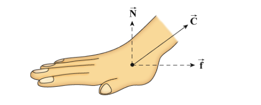

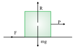
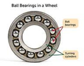


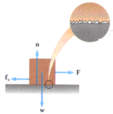
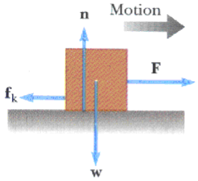
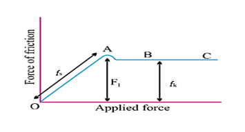
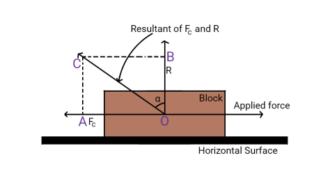


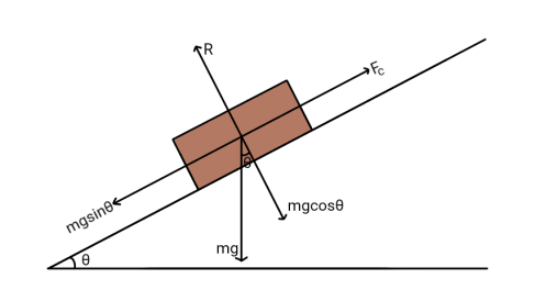


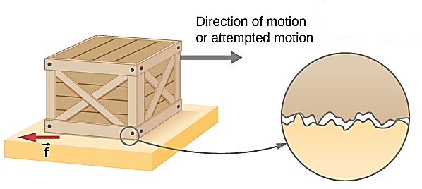
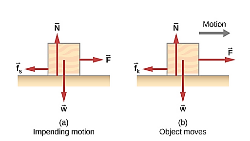
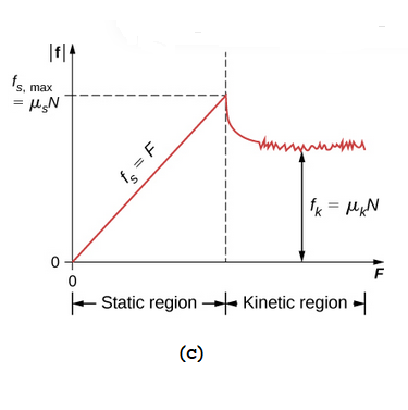
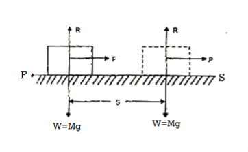
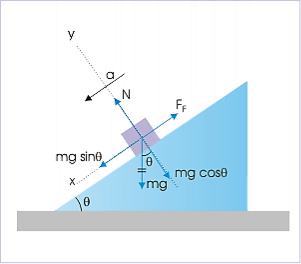
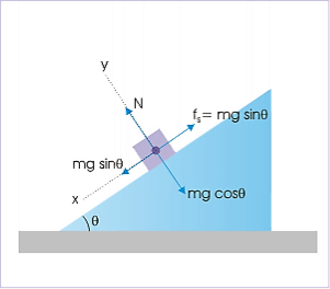
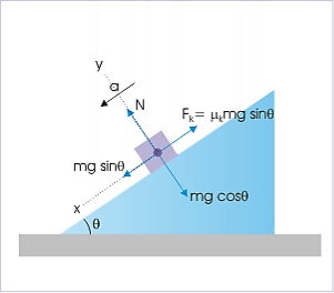
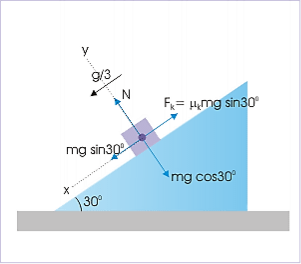





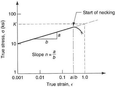
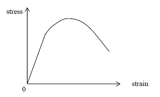
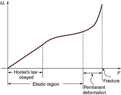


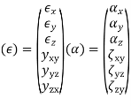

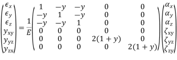

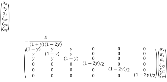


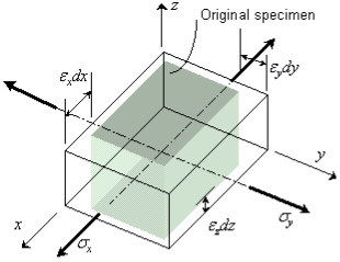


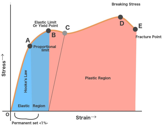
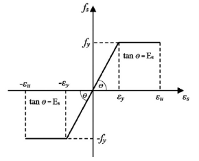

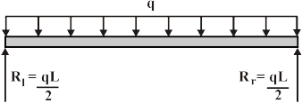

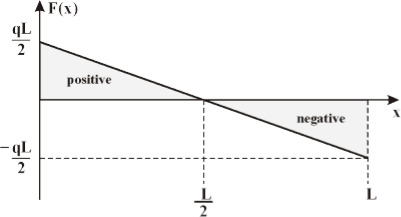
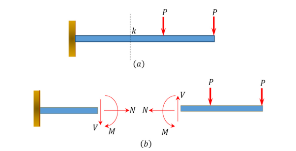
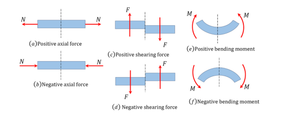
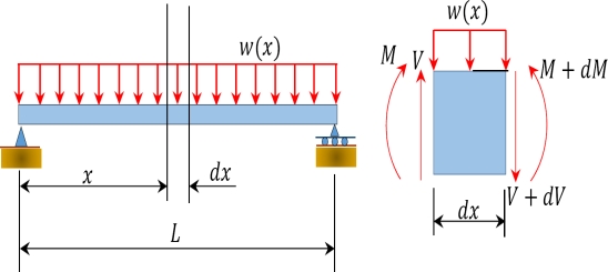


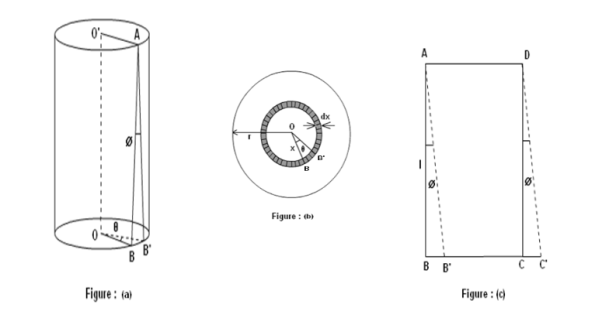


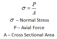
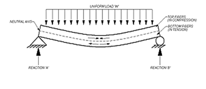
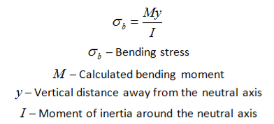
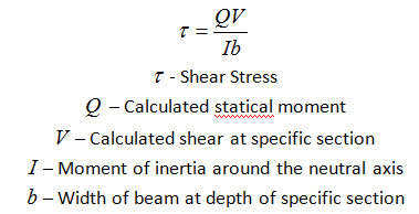


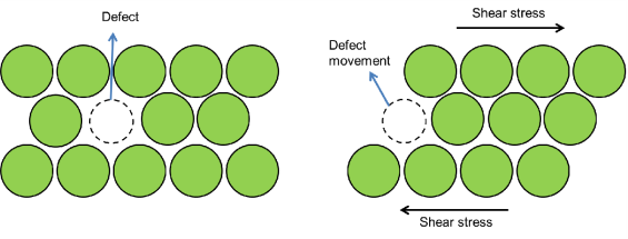


![[(1+ ν)∕6E ]σ2
Max](https://glossaread-contain.s3.ap-south-1.amazonaws.com/epub/1642923724_9163418.png)


![[ ]1∕2
σMises = (σ1 − σ2)2 + (σ1 − σ3)2 + (σ2 − σ3)2 .](https://glossaread-contain.s3.ap-south-1.amazonaws.com/epub/1642923725_0801935.png)
