UNIT-IV
FRAMES OF REFERENCES AND RIGID BODY DYNAMICS
Mechanics is that branch of science which deals with the motion of particles. In order to describe the motion of a particle a coordinate system is required. The choice of coordinate system depends upon the nature of the problem. But generally motion is studied in a coordinate system attached to the earth. Since the earth is rotating about its axis and also about the sun, the coordinate system attached to it is an accelerated system.
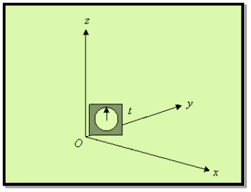
A frame of reference is a set of coordinates (for example x, y & z axes) with respect to whom any physical quantity can be determined.
A “frame of reference” is just a set of coordinates; we use to measure positions, velocities and time.
A point in space is specified by its three coordinates (x, y, z) and an “event” like a little explosion specified by a place and time: (x, y, z, t).
|
Figure 1: Frame of reference
INERTIAL & NON-INERTIAL FRAMES
- Inertial frames of reference
The inertia of a body is the resistance of changing its state of motion.
Uniformly moving reference frames (e.g. those considered at 'rest' or moving with constant velocity in a straight line) are called inertial reference frames.
Or
An inertial frame is defined as one in which Newton’s law of inertia holds that is anybody which isn’t being acted on by an outside force stays at rest if it is initially at rest, or continues to move at a constant velocity if that’s what it was doing to begin with.
Special relativity deals only with physics viewed from inertial reference frames.
If we can neglect the effect of the earth’s rotations, a frame of reference fixed in the earth is an inertial reference frame.
An example of a non-inertial frame is a rotating frame such as a carousel.
Let us understand it by an example; suppose a body is kept on the surface of the earth, for a person on earth it is at rest while for a person on the moon it is in motion so what is my inertial frame here?
Actually, the term inertial frame is relative i.e. first we assume a reference frame to be the inertial frame of reference. So a more general definition of an inertial frame would be: Inertial frame is at rest or moves with constant velocity with respect to my assumed inertial reference frame.
- Non-inertial frame of reference
A frame that is accelerated with respect to the assumed inertial frame of reference. Newton’s law will not hold true in these frames.
So in the above example if I assume earth to be an inertial reference frame then moon becomes a non-inertial reference frame as it is in accelerated motion with respect to earth. But if we want to make Newton’s law hold here we need to take some mysterious forces also known as pseudo forces.
GALILEAN TRANSFORMATIONS
Galilean Coordinate Transformations: For simplicity: - Let coordinates in both references equal at (t = 0). Use Cartesian coordinate systems.
Newton’s laws are only applicable at inertial reference frames. According to Galilean transformations, Newton’s laws are invariant at any inertial reference frame. In other words, the mechanical movement of a particle is exactly the same at two different reference frames, If both of them are inertial (i.e. one moves with constant velocity w.r.t the other & vice versa).
There is no mechanical experiment by which one can distinguish whether a system is at rest or is moving with a constant speed in a straight line (Galilean relativity).
Suppose we know from experiment that these laws of mechanics are true in one frame of reference. How do they look in another frame, moving with respect to the first frame?
To find out, we have to figure out how to get from position, velocity and acceleration in one frame to the corresponding quantities in the second frame.
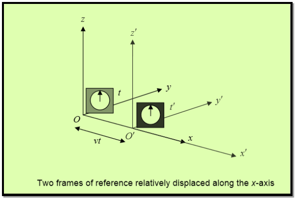
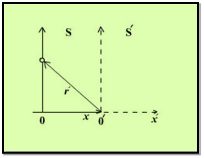
Obviously, the two frames must have a constant relative velocity, otherwise the law of inertia won’t hold in both of them. Let’s choose the coordinates so that this velocity is along the x-axis of both of them.
|
Figure 2: Frame of reference relatively displaced along the x-axis
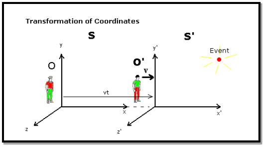
Notice we also throw in a clock with each frame. Suppose S′ is moving relative to S at speed v along the x-axis. For convenience, let us label the moment when O′ passes O as the zero point of timekeeping. That mean at t=0 O and O’ coincide with each other.
Now let us try to find the coordinates of the event (x, y, z, t) in S′
It’s easy to see t′ = t
We synchronized the clocks when O′ passed O. Also, evidently, y′ = y and z′ = z, from the figure.
We can also see that x = x′ +vt.
Thus (x, y, z, t) in S corresponds to (x′, y′, z′, t′) in S′, where
x = x′ +vt.
y = y’
z = z’
t =t’
That’s how positions transform; these are known as the Galilean Transformations.
Velocity
The velocity in S′ in the x′ direction is given by u’x

This is obvious anyway it’s just the addition of velocities formula.
ux = u’x +v
Acceleration

Since v is constant. That is to say,
a’x =ax
The acceleration is the same in both frames. This again is obvious as the acceleration is the rate of change of velocity, and the velocities of the same particle measured in the two frames differ by a constant factor-the relative velocity of the two frames.
LORENTZ TRANSFORMATION
As discussed above we need a transformation between two inertial frames which
(a) Preserves the velocity of light
(b) Keeps the forms of laws of physics invariant.
Lorentz transformation is the relationship between two different coordinate frames that move at a constant velocity and are relative to each other. The name of the transformation comes from a Dutch physicist Hendrik Lorentz.
The Galilean transformation nevertheless violates Einstein’s postulates, because the velocity equations state that a pulse of light moving with speed c along the x-axis would travel at speed c−v in the other inertial frame.
|
Figure 3: Transformation of coordinates
Specifically, the spherical pulse has radius r=ct at time t in the unprimed frame, and also has radius r′=ct′ at time t' in the primed frame.
Expressing these relations in Cartesian coordinates gives
x2+y2+z2−c2t2 =0 ………..(1)
x′2+y′2+z′2−c2t′2=0 ………..(2)
The left-hand sides Equations and can be set equal because both are zero.
Because y=y′ and z=z′ so, we obtain
x2−c2t2 =x′2−c2t′2 ………..(3)
However this cannot be satisfied for nonzero relative velocity v of the two frames if we assume the Galilean transformation results in t=t′ with x=x′+vt′.
To find the correct set of transformation equations, assume the two coordinate systems S and S′
The laws of mechanics are invariant under Galilean transformations, whereas electrodynamics and Maxwell’s equations are varying under this transformation. This shows that the velocity of light will have different values for different observers moving with different uniform velocities. But the speed of light is invariant in all inertial frames of reference; hence, Galilean transformations need to be modified.
Lorentz deduced the transformation equations, which are in agreement with the results of Michelson–Morley experiment. The Lorentz transformations are deduced as given below.
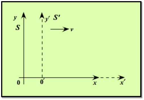
Lorentz transformation equations are developed. Let x, y, z and t be the space and time coordinate in rest system or standard system. The system with x', y', z' moves with velocity 'v' along the x-axis.
The origins at t=t'=0 coincide. The most general transformation equations relating the coordinates of an event in two systems can be written as,
x’ = Ax +Bt ………..(4)
y’ = y ………..(5)
z’ = z ………..(6)
t’ = Cx +Dt ………..(7)

|
Figure 4: Transformation of coordinates
The transformations are linear.
If they are not linear one system would predict acceleration while in other system velocity was even constant.
Because of symmetry, y' and z' axes are left unchanged by the transformation.
Constant can be calculated by using the following boundary conditions.
- Observers in S and S' see (O') the origin of S' as
x = vt
x’ = 0
Substituting values of x and x' in equation (4) We get
0 = Avt +Bt
i.e. B =- Av ………..(8)
- Observer in S' and S see the origin (O) of S as
x' = vt
x = 0
Substituting values of x and x' in equation (4) we get
-vt’ =Bt ………..(9)
Substituting the value of B from equation (8), we get
-vt’ =- Avt ………..(10)
In equation (7) put x=0 we get
t’ = Dt
So equation (10) become
-v Dt =- Avt
A =D ………..(11)
- A light pulse is sent out from the origin of S towards x at t=0, its location is given by
x= ct
x’ = ct’
Substituting values of x and x' in equation (4), we get
ct’ = Act +Bt
Substituting the value of B from equation (8), we get
ct’ = Act +(- Avt) ………..(12)
Substituting values of x and D from eq no (11) in eq no.(7) , we get
t’ = Cct +At
Substituting above value of t' in eq no.(12) , we get
c(Cct +At) = Act - Avt
or
Cc2t +Act =Act - Avt
Cc2t =Avt
Or
C =-A  ………..(13)
- A light pulse is emitted along y axis in S system at t=0, its coordinate in both systems are
|
Figure 5: Frame S and S’
y= ct, x=0
r’=ct’ where
using equation (5)
r’2 = x’2+y’2
using equation (5)
y’= y= ct
and from equation (4) and (7)
x’ = Bt = -Avt
t’= Dt =-At
Therefore r’2 = x’2+y’2 become
c2t’2 = (-Avt)2 +(ct)2
Substituting value of t' above equation became
c2A2t2 = A2v2t2 +c2t2
(c2 - v2) A2t2 = c2t2
A2 = 
A = 
A =  ………..(14)
Substituting the Values of A, B, C, D in equation (1) and (4)
So the Lorentz transformation equations would be,
x’=  -
- 
x’=  (x-vt)
x’= (x-vt)
Where 
And
t’ = -  +
+ 
t’=  ( t -
( t -  )
)
Lorentz transformation equations therefore are
x’=  (x - vt)
y’ =y
z’ = z
t’=  ( t -
( t -  )
)
Or these can be written as
x’=  (x-vt)
y’ =y
z’ = z
t’=  ( t -
( t -  )
)
Where 
This set of equations, relating the position and time in the two inertial frames, is known as the Lorentz transformation. They are named in honour of H.A. Lorentz (1853–1928), who first proposed them. Interestingly, he justified the transformation on what was eventually discovered to be a fallacious hypothesis.
The reverse transformation expresses by the following equations. Simply interchanging the primed and unprimed variables and substituting gives:
x=  (x’+ vt)
y =y’
z = z’
t=  (t’ +
(t’ +  )
)
Key Takeaways
- Thus (x, y, z, t) in S corresponds to (x′, y′, z′, t′) in S′, where x = x′ +vt, y = y’, z = z’, t =t’ these are known as the Galilean Transformations.
- This set of equations, relating the position and time in the two inertial frames, is known as the Lorentz transformation.
- Lorentz transformation are given as x’=
 (x-vt), y’ =y, z’ = z and t’=
  ( t -
( t -  ) Where
CYLINDRICAL COORDINATES
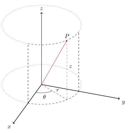
Cylindrical coordinates are essentially polar coordinates in R3. Remember, polar coordinates specify the location of a point using the distance from the origin and the angle formed with the positive x axis when traveling to that point. Cylindrical coordinates use those same coordinates, and add z for the third dimension.
In other words, to find a point (r,θ,z) in cylindrical coordinates, find the point (r,θ) in the xy plane, then move straight up (parallel to the z axis) according to the third dimension given. The first two are the polar radius and angle and the third component is the same as the rectangular z-coordinate.
|
Figure 6: Cylindrical coordinates
Converting rectangular coordinates to cylindrical coordinates and vice versa is straightforward, provided you remember how to deal with polar coordinates. To convert from cylindrical coordinates to rectangular, use the following set of formulas:
x=rcosθ
y=rsinθ
z=z
Notice that the first two are identical to what we use when converting polar coordinates to rectangular and the third simply says that the z coordinates are equal in the two systems.
SPHERICAL COORDINATES
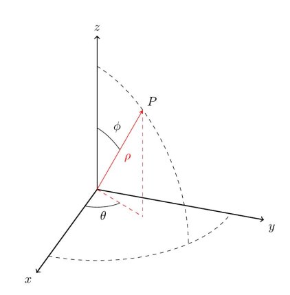
Spherical coordinates are similar to the way we describe a point on the surface of the earth using latitude and longitude. By specifying the radius of a sphere and the latitude and longitude of a point on the surface of that sphere, we can describe any point in R3. To describe the latitude and longitude, we use two angles: θ (the angle from the positive x axis) and ϕ (the angle from the positive z axis). We therefore have three coordinates (ρ,θ,ϕ), where ρ is the radius of the sphere.
|
Figure 7: Spherical coordinates
where the first component is the distance from the origin to the point, the second component is the polar angle and the third component is the altitude angle measured from the positive z-axis to the line connecting the origin and the point.
Note that
0≤θ<2π
0≤ϕ≤π
ρ≥0
The formulas that we need in order to convert between rectangular and spherical coordinates are given below, without derivation
ρ=x2+y2+z2
x=ρcosθsinϕ
y=ρsinθsinϕ
z=ρcosϕ
Example: Convert (3, π/4, 4) in cylindrical coordinates to rectangular coordinates.
Solution:
Use the formulas, noting that r=3, θ=π/4, and z=4.
x=rcosθ=3cosπ/4= 
y=rsinθ=3sinπ/4= 
z=4
Therefore point is ( ) in rectangular coordinates.
To go in the other direction (from rectangular coordinates to cylindrical), use the following set of formulas (again, the first two are exactly what we use to convert from rectangular to polar in R2:
r=x2+y2
θ=tan−1
z=z
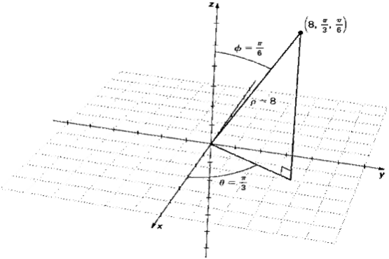
Example: Plot the point with spherical coordinates (8, π/3, π/6) and express its location in both rectangular and cylindrical coordinates.
Solution:
Use the equations in Note to translate between spherical and cylindrical coordinates
ρ=x2+y2+z2
x=ρcosθsinϕ = 8sin(π/6)cos(π/3) = 8(1/2)1/2=2
y=ρsinθsinϕ =8sin(π/6)sin(π/3)=8(1/2) =2
=2
z=ρcosϕ =ρcosφ =8cos(π/6)= 8( =4
=4
The point with spherical coordinates (8,π/3,π/6) has rectangular coordinates (2, 2 4
4 )
)
Finding the values in cylindrical coordinates is equally straightforward:
r=ρsinφ=8sinπ/6= 4
θ= θ
z=ρcosφ=8cosπ/6= 4
Thus, cylindrical coordinates for the point are (4,π/3, 4 )
)
.
|
Figure 8: Coordinate System
Key Takeaways
- cylindrical coordinates system is given by set of formulas: x=rcosθ, y=rsinθ and z=z
- spherical coordinates are given as ρ=x2+y2+z2 , x=ρcosθsinϕ, y=ρsinθsinϕ and z=ρcosϕ
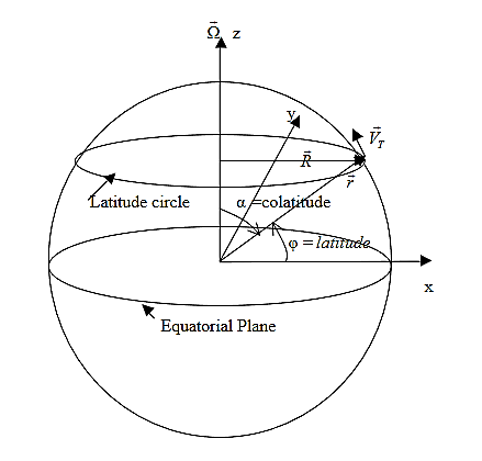
The Coriolis force is a force which acts upon any moving body in an independently rotating system. The most well-known application of the Coriolis force is for the movement or flow of air across the Earth. The effect is named after the French physicist Gaspard de Coriolis (1792-1843), who first analysed the phenomenon mathematically.
The Earth rotates about its axis from west to east once every 24 hours. Consequently, an object moving above the Earth in a generally northerly or southerly direction, and with a constant speed relative to space, will be deflected in relation to the rotation of the Earth. This deflection is clockwise, or to the right, in the Northern Hemisphere and anticlockwise, or to the left, in the Southern Hemisphere.
Moving air undergoes an apparent deflection from its path, as seen by an observer on the Earth. This apparent deflection is the result of the Coriolis force. The amount of deflection the air makes is directly related to both the speed at which the air is moving and its latitude. Therefore, slowly blowing winds will be deflected only a small amount, while stronger winds will be deflected more. Likewise, winds blowing closer to the poles will be deflected more than winds at the same speed closer to the equator. The Coriolis force is zero right at the equator.
The Coriolis force only acts on large objects like air masses moving considerable distances. Small objects, for example ships at sea, are too small to experience significant deflections in direction due to the Coriolis Force.
Any force or combination of forces can cause a centripetal or radial acceleration. Just a few examples are the tension in the rope on a tether ball, the force of Earth’s gravity on the Moon, friction between roller skates and a rink floor, a banked roadway’s force on a car, and forces on the tube of a spinning centrifuge.
Any net force causing uniform circular motion is called a centripetal force. The direction of a centripetal force is toward the center of curvature, the same as the direction of centripetal acceleration. Time derivatives in fixed and rotating coordinates
|
Figure 9: Time derivatives in fixed and rotating coordinates
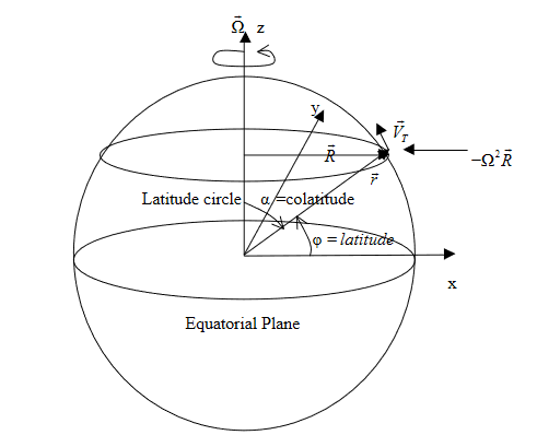
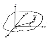
Let  = position vector from the origin (center of the earth). Then, we can find out that the instantaneous tangential velocity of a particle at any distance
  (
( +
+ where a = mean radius of earth and z = altitude above ground) is given by
 ……….(1)
Here  is the vector angular velocity of the earth rotation.
We can see this by first looking at the magnitude of  . According to the above figure,
 ……….(2)
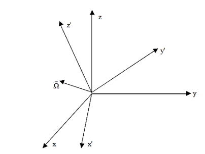
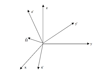
Now, let's try to relate  in 2 reference frames:
a) Fixed (absolute) system ( )
)
b) Rotating ( ) system (
 )
)
|
Figure 10: Rotating coordinates
Now, a vector  is the same vector no matter what coordinate system it is viewed from. This

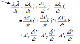
Given that the primed system is rotating, however, the time derivative of  will be different if viewed from the 2 systems. Mathematically, we have
'a' for absolute
|
……….(3)
Note that the primed unit vectors vary with time.
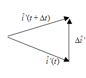
Due to rotation of unit vector
|
Figure 11: Rotation of unit vector
Recall earlier that 
 a particle rotating at angular velocity
  . Since

therefore

The above is correct only for a vector whose length does not change. The same is true for the unit vectors, therefore
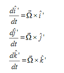 ……….(4)
If we now look at  in the reference frame of the rotating (primed) system, then
( ) to be fixed.
 ……….(5)
which is a time rate of change in  seen from the rotating reference frame and is analogous to
  earlier.
Thus, from (3), we can write
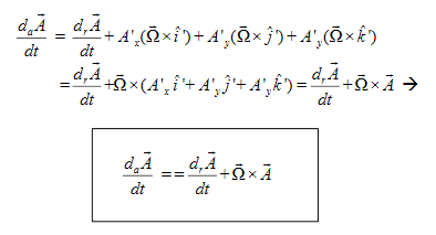 ……….(6)
Let's look at a physical interpretation. If  , then we can write
|
……….(7)
In another word,

EQUATION OF MOTION IN ABSOLUTE AND ROTATING COORDINATES
Let's now apply concepts from the previous section to any arbitrary velocity vector of a particle assuming that the origins of the rotating and fixed (inertial) frames are the same. In this case, the position vector to any location is the same in both systems.
Our goal is to find the equations of motion in the absolute and rotating coordinates.
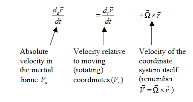
Now, we just showed that
 ……….(8)
where  is the relative velocity (we shall drop subscript r from now on).
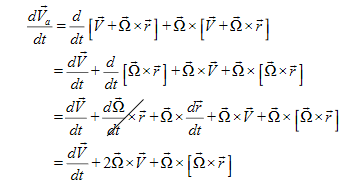
Apply Eq.(6) to  in (8)
|
……….(9)
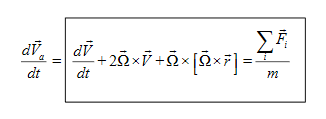
Apply the Newton's second law
|
……….10)
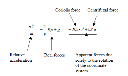
The part in the box is the equation of motion in the rotating coordinate system.
It describes the change of (relative) velocity in time subjecting the net force. The forces on the right hand side are real forces, and the second and third term on the left arises because of the coordinate rotation, and there are apparent (not real) forces. We will discuss them in more details in the following.
We will look at the last term one the left with respect to an earth oriented coordinate system:
|
Figure 11: Earth oriented coordinate system
Note that  =
=  cosφ.
cosφ.
Look at the last term in (10)

We can write it as

Using this we can rewrite equation (10) as
|
Abs. Accel = Rel. Accel. + Coriolis accel + (-Centripetal accel ) = Net real force
This is a very important equation.
How do we make use of this equation?
Let's look at the forces on the right hand side of (11) in the real atmosphere. They are
Gravity =  (force per unit mass)
PGF (per unit mass) = -  ∇ρ
∇ρ
These are real forces (those seen and felt in an inertial / fixed reference frame), so let's put them into the equation:
|
………(12)
this is the acceleration that we see and
measure in our earth coordinate system
– not an inertial frame, but the next 2
terms take that into account.
Rearranging (12)
|
………..(13)
Equation (13) is "THE EQUATION OF MOTION".
Even though a rigid body is composed of an infinite number of particles, the motion of these particles is constrained to be such that the body remains a rigid body during the motion. In particular, the only degrees of freedom of a 2D rigid body are translation and rotation.
- Translation, rectilinear and curvilinear: Motion in which every line in the body remains parallel to its original position. The motion of the body is completely specified by the motion of any point in the body. All points of the body have the same velocity and same acceleration.
- Rotation about a fixed axis: All particles move in circular paths about the axis of rotation. The motion of the body is completely determined by the angular velocity of the rotation.
- General plane motion: Any plane motion that is neither a pure rotation nor a translation falls into this class. However, as we will see below, a general plane motion can always be reduced to the sum of a translation and a rotation.
Motion Relative to Translating Axes
Particle motion has been described using position vectors that were referred to fixed reference frames. The positions, velocities and accelerations determined in this way are referred to as absolute. Often it isn’t possible or convenient to use a fixed set of axes for the observation of motion. Many problems are simplified considerably by the use of a moving reference frame.
In the following we will restrict our attention to moving reference frames that translate but do not rotate.
|
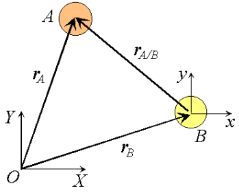
Figure 12: Observation of particle motion using a translating reference
Consider two particles A and B moving along independent trajectories in the plane, and a fixed reference O. Let rA and rB be the positions of particles A and B in the fixed reference. Instead of observing the motion of particle A relative to the fixed reference as we have done in the past, we will attach a non-rotating reference to particle B and observe the motion of A relative to the moving reference at B. Let i and j be basis vectors of the moving reference, then the position vector of A relative to the reference at B, denoted rA/B is,
rA/B =xi +yj
where the subscript stands for "A with respect to B" or "A relative to B". Observe that, as the moving frame does not rotate, basis vectors i and j do not change in time. Therefore, taking time derivatives, we obtain simply,


which can be interpreted as the velocity of A relative to B. Now we can express the absolute position vector of A as,

Differentiating the equation in time to obtain expressions for the absolute velocity and acceleration of particle A:

or the absolute velocity of A equals the absolute velocity of B plus the velocity of A relative to B, vA/B , and similarly for the acceleration. The relative terms are the velocity or acceleration measured by an observer attached to the moving reference at particle B.
|
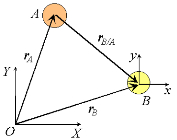
Figure 13: Relative velocities under change of translating reference.
What would happen if the moving reference were attached to A instead?

By comparison with expressions derived previously

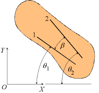
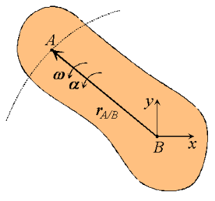
We proceed by demonstrating that every motion of a planar rigid body is associated with a single angular velocity ω and angular acceleration , describing the angular displacement of an arbitrary line inscribed in the body relative to a fixed direction.
|
Figure 14: Angular velocity and acceleration of a rigid body
Consider a rigid body undergoing plane motion. The angular positions of two arbitrary lines 1 and 2 attached to the body are specified by  1and
1and  2 measured relative to any convenient fixed reference direction. These are related to the intermediate angle
  shown as,
 2 =
2 =  1
1
Observe that as the body is rigid, requiring that the distance between each pair of points on the two lines 1 and 2 is constant, angle  must be invariant. Differentiating the relation above with this in mind,

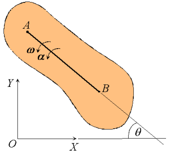
These hold for arbitrary lines attached to the body, implying in turn that the body can be associated with a unique angular velocity ω, defined as,

for an arbitrary line attached to the body. Arguing analogously, the body can be associated with a unique angular acceleration  defined as,
|
Figure 15: Angular velocity and angular acceleration of a rigid body
Consequently, we have the property that all lines on a rigid body in its plane of motion have the same angular displacement, the same angular velocity ω and the same angular acceleration. 
|
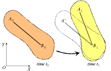
Figure 16: Decomposition of rigid body motion
Next, consider the motion of a rigid body over the interval t0 - t1 as shown, with arbitrary point B0 taken as reference. Clearly, the motion can be consider to occur in two stages: a translation with reference B0 taking arbitrary line A0 B0 to an intermediate position A’B1; and a rotation about point B1 taking A’B1 to its final position A1B1. This corresponds to a decomposition of the motion into the sum of a translation and a rotation. While the translational motion is described by the velocity  and acceleration
  of the reference point, the rotational motion is characterized by the unique angular velocity ω and angular acceleration
  associated with the body. Thus, we have the property that the motion of a rigid body can be decomposed into a translation of an arbitrary point within the body, followed by a rigid rotation of the body about this point. Further, the motion of an arbitrary point within the body is determined completely once the translational quantities
  and
and  and rotational quantities ω and
  are known.
Characteristics of rigid body motion:
- All lines on a rigid body have the same angular velocity ω and the same angular acceleration
 .
. - Rigid motion can be decomposed into the translation of an arbitrary point, followed by a rotation about the point.
Now we will derive equations that describe the motion.
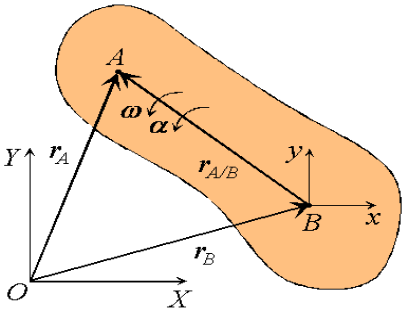
|
Figure 17: Definition of a translating reference attached to point B
Consider a rigid body moving in the plane with angular velocity ω and angular acceleration  , and two arbitrary points A and B of the body. We will examine the motion of this body in both, the fixed reference O shown, as well as relative to a non-rotating reference attached to point B. Proceeding, we express the absolute position of point A in terms of the absolute position of point B as,

where rA/B is the position of A relative to B. An analogous expression for absolute velocities follows by taking time derivatives,

where vA/B is the velocity of point A relative to the reference at B,

|
Figure 18: Motion of point A as seen by a translating observer at B
Now, as the body moves, point A traces a circular path of radius rA/B =  relative to point B, keeping the distance between the two unchanged. The angular velocity of this motion is simply the angular velocity ω of the rigid body. Then, using results derived previously for the time derivatives of rotating vectors we have:

or,

Observe that the expression reflects the decomposition of rigid body motion referred to previously. With B chosen as reference, the velocity of A is the vector sum of a translational portion vB and a rotational portion ω rA/B .
Proceeding to derive expressions for the acceleration of an arbitrary point of a rigid body, we differentiate the equation for velocities to obtain,

Where  A/B , the acceleration of point A relative to the reference at B, is simply
or,
Thus, like the absolute velocity, the absolute acceleration of point A is the vector sum of a translational portion |
Moment of inertia of rigid body
Rigid body is a continuous aggregation of particles. We, therefore, need to modify the summation in the expression of moment of inertia by integration as :
I = ∫r2đm
Evaluation of this integral for a given body is a separate task in itself. It is mathematically possible to evaluate this integral for bodies of regular shape. It would, however, be very difficult to evaluate the same for irregularly shaped rigid body. In such cases, it is pragmatic to resort to experimental methods to calculate moment of inertia. Mathematical evaluation of moment of inertia even for regularly shaped bodies would require specialized analysis and evaluation.
Two theorems, pertaining to moment of inertia, are of great help in the mathematical evaluation of moment of inertia of regularly shaped bodies. They are (i) parallel axes theorem and (ii) perpendicular axes theorem. These theorems extend the result of moment of inertia of basic geometric forms of rigid bodies to other axes.
Key Takeaways
- Even though a rigid body is composed of an infinite number of particles, the motion of these particles is constrained to be such that the body remains a rigid body during the motion.
- Translation, rectilinear and curvilinear: Motion in which every line in the body remains parallel to its original position. The motion of the body is completely specified by the motion of any point in the body. All points of the body have the same velocity and same acceleration.
- Rotation about a fixed axis: All particles move in circular paths about the axis of rotation. The motion of the body is completely determined by the angular velocity of the rotation.
- General plane motion: Any plane motion that is neither a pure rotation nor a translation falls into this class. However, as we will see below, a general plane motion can always be reduced to the sum of a translation and a rotation.
- All lines on a rigid body have the same angular velocity ω and the same angular acceleration
 .
. - Rigid motion can be decomposed into the translation of an arbitrary point, followed by a rotation about the point.
When all parts of a rigid body move parallel to a fixed plane, then the motion of the object is referred to as plane motion. There are two types of plane motion, which are given as follows:
The pure rotational motion: The rigid body in such a motion rotates about a fixed axis that is perpendicular to a fixed plane. In other words, the axis is fixed and does not move or change its direction relative to an inertial frame of reference.
The general plane motion: The motion here can be considered as a combination of pure translational motion parallel to a fixed plane in addition to a pure rotational motion about an axis that is perpendicular to that plane.
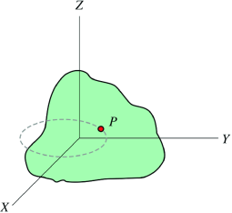
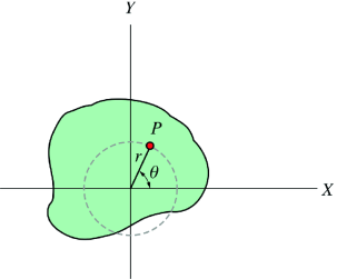
Suppose a rigid body of an arbitrary shape is in pure rotational motion about the z-axis (see Figure 19(a)). Let us analyze the motion of a particle that lies in a slice of the body in the x-y plane as in Figure 19(b). This particle (at point P) will rotate in a circle of fixed radius r which represents the perpendicular distance from P to the axis of rotation. If you look at any other particle in the object you will see that every particle will rotate in its own circle that has the axis of rotation at its center. In other words, different particles move in different circles but the center of all of these circles lies on the rotational axis. Suppose the particle moves through an arc length s starting at the positive x-axis. Its angular position is then given by
θ=s/r
r and θ are the polar coordinates of a point in a plane where θ is always measured from the positive x-axis. Because θ is the ratio of the arc length to the radius, it is a pure (dimensionless) number.
|
| ||
Figure 19(a): A rigid body of an arbitrary shape is in pure rotational motion about the z-axis
| Figure 19(b): The motion of a particle that lies in a slice of the body in the x-y plane
|
When a rigid body moves in such a way that one point in it remains fixed, then motion of the rigid body is called rotation about a point. The point which remains fixed during motion is called the centre of rotation.
Consider a body which is rotating about a point O. All the particles of the body will rotate about it. Since the body is rigid, the distance between all pairs remains fixed during the motion. Let us consider a particles P of the rigid body having position vector  . Let b be its distance from the origin O. The rigidity condition requires that
 = b
= b
Where b is constant.
Squaring the above both sides we obtain
 =
= 
 .
. =
=
Differentiate both sides with respect to time to obtain
 .
. +
+
 = 0
= 0
 .
. +
+
 = 0
= 0
 .
. = 0
= 0
This equation shown that whenever a rigid body rotates about a fixed point, the instantaneous velocity vector of any particle is always perpendicular to its instantaneous position vector.
Kinetic energy of rigid body in rotation
Kinetic energy of a particle or body represents the form of energy that arises from motion. We are aware that kinetic energy of a particle in translation is given by the expression:
K= mv2
mv2
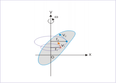
In pure rotation, however, the rigid body has no "over all" translation of the body. However, the body in rotation must have kinetic energy as it involves certain motion. A closer look on the rotation of rigid body reveals that though we may not be able to assign translation to the rigid body as a whole, but we can recognize translation of individual particles as each of them rotate about the axis in circular motion with different linear speeds. The speed of a particle is given by:
|
Figure 20: Kinetic energy of rigid body in rotation
Pure rotational motion Each particle of the body follows a circular path about axis in pure rotational motion.
vi= ωri
Thus, kinetic energy of an individual particle is :
Ki= mivi2
mivi2
where " Ki" is the kinetic energy of "i" th particle having a speed " vi". In terms of angular speed, the kinetic energy of an individual particle is:
Ki= mi(ωri2
Ki= mi(ωri)2
Now, the kinetic energy of the rigid body is sum of the kinetic energies of the particles constituting the rigid body:
K=∑Ki=∑ mi(ωri)2
We note here that angular speeds of all particles constituting the body are same. Hence, the constant "1/2" and " ω2" can be taken out of the summation sign :
K = ω2∑mi(ri)2
However, we know that:
I=∑mi(ri)2
Combining two equations, we have:
K=  Iω2
Iω2
This is the desired expression of kinetic energy of a rigid body rotating about a fixed axis i.e. in pure rotational motion. The form of expression of the kinetic energy here emphasizes the correspondence between linear and angular quantities. Comparing with the expression of kinetic energy for translational motion, we find that "moment of inertia (I)" corresponds to "mass (m)" and "linear speed (v)" corresponds to "angular speed (ω)".
We can also interpret the result obtained above from a different perspective. We could have directly inferred that expression of kinetic energy in rotation should have an equivalent form as:
K (Kinetic energy)=  x(inertia)x(speed)2
In rotation, inertia to the rotation is "moment of inertia (I)" and speed of the rigid body is "angular speed (ω)". Substituting for the quantities, we have the expression for kinetic energy of rigid body in rotation as :
K=  Iω2
Iω2
Comparing this equation with the expression of the sum of kinetic energy of individual particles as derived earlier:
K = ω2∑mi(ri)2
Clearly,
I= ∑mi(ri)2
This conclusion, thus, clearly establishes that the expression as given by ∑mi(ri)2
indeed represents the inertia of the rigid body in rotation.
Key Takeaways
- When all parts of a rigid body move parallel to a fixed plane, then the motion of the object is referred to as plane motion. There are two types of plane motion, which are given as follows:
- The pure rotational motion: The rigid body in such a motion rotates about a fixed axis that is perpendicular to a fixed plane. In other words, the axis is fixed and does not move or change its direction relative to an inertial frame of reference.
- The general plane motion: The motion here can be considered as a combination of pure translational motion parallel to a fixed plane in addition to a pure rotational motion about an axis that is perpendicular to that plane.
- A rigid body rotates about a fixed point, the instantaneous velocity vector of any particle is always perpendicular to its instantaneous position vector.
- I= ∑mi(ri)2 the expression as given by ∑mi(ri)2 indeed represents the inertia of the rigid body in rotation.
Consider a rigid body which a rotating about a fixed point with an angular velocity  . Choose the origin O at the fixed point and axes as shown in Figure 21
The velocity of particle i having position vector is
is
 =
= 

 …………(1)
If mi is the mass of particle i then its angular momentum about the fixed point O is
 =
= 
 …………(2)
Substituting the value of  , it takes the form
 =
= 


 …………(3)
|
Figure 21: Angular momentum about a point of a rigid body in planar motion
The angular momentum of rigid body can be obtained by summing the above equation over all the particles of the rigid body. Thus
Using the vector relation
Eq. (4) may be written as
Let (xi, yi, zi) be the cartesian coordinates of particle i, then
If ωx, ωy and ωz are the components of angular velocity along coordinate axes then
Now take the dot product of
Substitutes these values in eq. (6) to obtain
In this expansion it is useful to introduce the following abbreviations.
…………(11) These nine quantities Ixx, Ixy,….Izy are the components of the moments of intertia of the body about the fixed x,y,z axes. The components Ixx, Iyy and Izz are called the moments of intertia about x-axis, y-axis and z-axis respectively and the components Ixy,Iyz, …., Izy are called the products of intertia. A quantity such as the moment of intertia is called a tensor of second rank. In terms of the moments of intertia and products of intertia,
…………(12) This equation shows that the angular momentum vector Eq. (11) shows that
Thus the rotational behaviour of a rigid body about a given point it determined by a set of six quantities: the three moments of intertia and the three products of intertia. These moments of intertia and products of intertia will in general be function of time.
|
Key Takeaways
- These nine quantities Ixx, Ixy,….Izy are the components of the moments of intertia of the body about the fixed x,y,z axes. T
- he components Ixx, Iyy and Izz are called the moments of intertia about x-axis, y-axis and z-axis respectively and the components Ixy,Iyz, …., Izy are called the products of intertia.
- A quantity such as the moment of intertia is called a tensor of second rank.
 =
=


A model that describes the translational and rotational motion of one or more objects must express the motion of those objects with respect to a set of coordinate systems. It must be possible to determine the position, velocity, angular orientation, and rotational rate of each object in the different coordinate systems to perform system simulation. For example, when Newton's Law of motion is applied to determine the translational motion of an object, you must determine the direction of forces and moments acting on the object with respect to inertial (nonrotating and nonaccelerating) space. This may be difficult, because the forces and moments acting on the body are frequently defined in terms of a body-fixed coordinate system that accelerates and rotates with the object.
In an aircraft flight simulation, there are typically two primary coordinate systems. One coordinate system is fixed to the body of the aircraft and moves with it in both translation and rotation. This coordinate system has its origin at the aircraft center of mass and is called the body-fixed coordinate system. The other originates on the surface of the earth at a defined location and is called the earth-fixed coordinate system. The relations between these coordinate systems define the aircraft position, velocity, Euler angles (roll, pitch, and yaw angles), and rotation rates.
In the general case, the displacement of a rigid body is determined by a translation plus a rotation about some axis. This result is a generalization of Euler’s theorem, which is sometimes known as Chasles' theorem. In practice, this means that six parameters are needed to define the position of a 3D rigid body. For instance, we could choose three coordinates to specify the position of the center of mass, two angles to define the axis of rotation and an additional angle to determine the magnitude of the rotation.
Unlike the motion about a fixed point, it is not always possible to define an instantaneous axis of rotation. Consider, for instance, a body which is rotating with angular velocity ω and, at the same time, has a translational velocity parallel to ω.
It is clear that, in this case, all the points in the body have a non-zero velocity, and therefore an instantaneous center of rotation cannot be defined. It turns out that, in some situations, the motion of the center of mass of a 3D rigid body can be determined independent of the orientation.
Consider, for instance, the motion of an orbiting satellite in free flight in this situation, the sum of all external forces on the satellite does not depend on the satellite's attitude, and, therefore, it is possible to determine the position without knowing the attitude. In more complex situations, however, it may be necessary to solve simultaneously for both the position of the center of a mass and the attitude. The velocity, Vp, and acceleration, ap, of a point, P, in the rigid body can be determined if we know the velocity, vO', and acceleration, aO', of a point in the rigid body, O', as well as the body's angular velocity, ω, and acceleration, a.

Here, rp' is the position vector of the point, P, relative to O'. We point out that the angular velocity and P angular acceleration are the same for all the points in the rigid body.
Motion in two dimension: Motion in a plane is described as two dimensional motion. Example: An ant moving on the top surface of a desk is example of two dimensional motion. Projectile and circular motion are examples of two dimensional motion.
Motion in three dimension: Motion in space which incorporates all the X, Y and Z axis is called three dimensional motion. Example: Movement of gyroscope is an example of three dimensional motion.
References Books
- Engineering Mechanics, 2nd ed.- MK Harbola, Cengage Learning
- “Introduction to Mechanics”, M.K.Vermas,
- Mathur, ‘Mechanics’, S. Chand Publishing.
