Unit-5
Electrical Installations
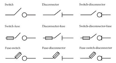
It has one switch unit and one fuse unit. When the breaker is operated the contact to the switch is close and supply passes through the fuse unit to output. In fuse switch unit there is only fuse unit which acts as a switch. During operating the fuse unit closes the input and output of the breaker.
MCB is a switch which automatically turns off when the current flowing through it passes the maximum allowable limit. Generally, MCB is designed to protect against over current and over temperature faults. In MCB there are two contacts one movable and other non-movable. When the current exceeds the predefined limit, a solenoid forces the moveable contact to open and the MCB turns off, thereby stopping the current from flowing in the circuits.
It mainly consists of one bi- metallic strip, one trip coil and one hand operated on-off lever. The current in MCB flows from left side of circuit to bimetallic strip further going into the current coil, moving contact and at last through right side of circuit. When circuit is overloaded the bimetallic strip is overheated.
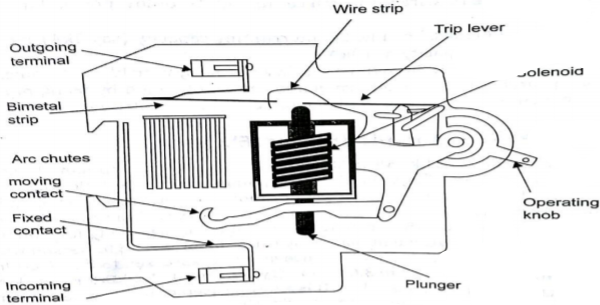
This deformation of bimetallic strip causes displacement in the latch. This displacement releases the spring through which the MCB is connected to the moving contact. This spring makes moving contact to open MCB.
The current coil or trip coil placed in such a manner that during SC faults, the MMF of that coil causes its plunger to hit the same latch point and force the latch to be displaced. Hence, the MCB will open in the same manner.
They are frequently used in domestic and industrial purposes. The MCB detects faults like switching, overload, short circuit protection and overload protection.
An Earth Leakage Circuits Breakers (ELCB) is a device used to directly detect currents leaking to earth from an installation and cut the power. There are two types of ELCBs:
(i) Voltage Earth Leakage Circuits Breaker (voltage -ELCB)
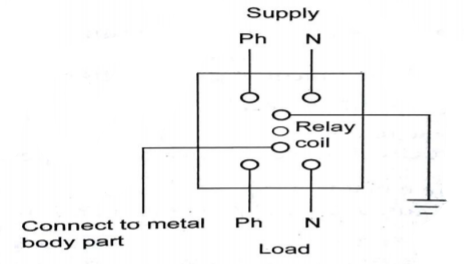
It consists of a relay coil; one end of that coil is connected to the metal body and other to the ground. When voltage on the equipment body rises to 50V (danger level) the current in the relay loop moves the relay contact by disconnecting the supply current and saves from electric shock.
(ii) Current Earth Leakage Circuits Breaker (Current -ELCB)
It is mostly commonly used ELCB. It consists of transformer having two primary (neutral and line wire) windings and one secondary winding. In balanced condition there is no current in secondary because the neutral wire balances the current through the phase wire.
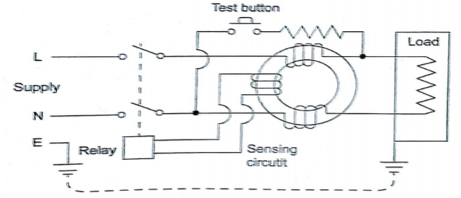
During fault a small current flow to ground causing imbalance between line and neutral currents. As a result of which current is induced in secondary winding. The sensing circuit connected to the secondary sends signal to the tripping system and the contact is tripped.
Moulded case circuits breakers are electromechanical devices which protect a circuit from over current and short circuits. They provide over current and short circuits protection for circuits ranging from 63A up to 3000 A. They are used for heavy duty applications as they have high current ratings. They provide electric feeder protection, capacitor bank protection, generator protection, welding applications, low current application that require adjustable trip setting and motor protection.
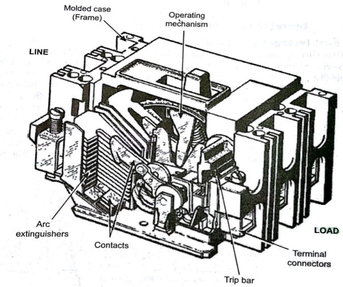
The are made up of heavy duty insulated plastic. MCCB has a bimetallic contact that expands and contacts when there is change in temperature. When current exceeds the adjustable trip value the contact gets heated and expands. The fault currents in MCCB can be interrupted immediately. Whenever a fault occurs, the extremely high current induces a magnetic field in a solenoid coil located inside the breaker – this magnetic induction trips a contact and current it interrupted
Types of Wiring
The wires used for domestic or industrial wiring are classified into different groups as
(i) According to the conductor material used
(a) Copper conductor cables
(b) Aluminium conductor cable
(ii) According to number of cores
(a) Singles core cable (SCC)
(b) Double core or twin core cables (DCC)
(c) Three core cables
(d) four core cables
(e) Two cores with earth continuity conductor cables
(iii) According to type of insulation
(a) Vulcanized Indian rubber (VIR) insulated wires/cables
(b) Tough rubber sheathed (TRS) or cable tyre sheathed (CTS) cables
(c) Polyvinyl chloride (PVC) cables
(b) Lead sheathed cables
(e) Weather proof cables
(f) Flexible cords and cables
(g) XLPE cables
(IV) According to the voltage at which they are manufactured
(a) Low tension (LT) cables – up to 1000V
(b) High tension (HT) cables – up to 11kV
(c) Super tension (ST) cables – from 22-33kV
(d) Extra high tension (EHT) cables – from 33-66kV
(e) Extra super voltage cables – beyond 132 kV
Earthing
It means connecting electrical equipment to earth with very low resistance wire. This ensures safe discharge of electrical energy due to failure of the insulation line coming in contact with the casing, etc. Earthing brings the potential of the body of the equipment to zero.
The main purpose of Earthing is to protect the operating personnel from shock. Under unbalanced load maintain the line voltage. To avoid risk of fire due to leakage currents. For protecting the equipment.
Methods of Earthing:
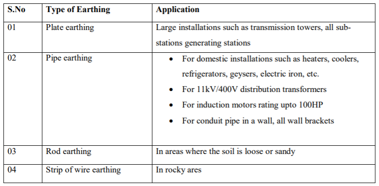
(i) Plate earthing: A copper plate of dimension 60cm x 60cm x 3.18 is used for earthing. The plate is buried in ground and layered with coal and salt. Then water is poured to maintain the earth’s electrode resistance below maximum value. The earth wire is bolted to the earth plate.
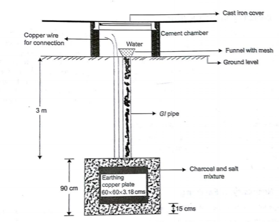
(ii) Pipe earthing:
The earth’s electrode made of galvanized iron pipe with holes on surface is placed upright in wet ground. In order to maintain the earth’s resistance, the pipe is filled with mixture of salt and coal. 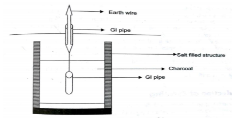
This system can carry larger leakage currents compared to plate earthing method.
(iii) Rod earthing: It is similar to pipe earthing method. A copper rod is buried upright in the earth manually or with pneumatic hammer. The length of embedded electrodes in soil reduces earth resistance to a desired level.
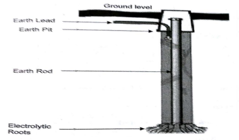
(iv) Strip or wire earthing: In this the earthing strip electrodes are buried in horizontal trenches of depth 0.5m. The copper plate or round conductors are used. The length of the conductor buried in the ground would give a sufficient earth resistance and this length should not be less than 15m. The electrodes shall be as widely distributed as possible in a single straight or circular trench radiating from a point. This type of earthing is used where the earth bed has a rocky soil and excavation work is difficult.
Application
