UNIT 4
Projections of lines
First and third angle projections
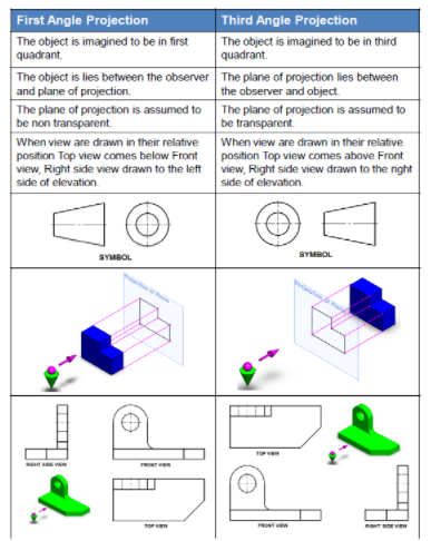
Every engineer must know how to read engineering drawings and the most integral part of this is knowing the difference between first and third angle projection. A collection of 2D drawings can be used to represent a 3D object in orthographic projection and consists of six orthographic views (Top, Bottom, Right, Left, Front and Back view) also known as six principle views. Out of these six, front, right side and top view are the most commonly used ones.
- First-angle projection: In this type of projection, the object is imagined to be in the first quadrant. Because the observer normally looks from the right side of the quadrant to obtain the front view, the objects will come in between the observer and the plane of projection. Therefore, in this case, the object is imagined to be transparent, and the projectors are imagined to be extended from various points of the object to meet the projection plane. When these meeting points are joined in order on the plane they form an image, thus in the first angle projection, any view is so placed that it represents the side of the object away from it. First angle projection is often used throughout parts of Europe so that it is often called European projection.
2. Third-angle projection: In this type of projection, the object is imagined to be in the third quadrant. Again, as the observer is normally supposed to look from the right side of the quadrant to obtain the front view, in this method, the projection plane comes in between the observer and the object. Therefore, the plane of projection is assumed to be transparent. The intersection of this plan with the projectors from all the points of the object would form an image on the transparent plane.
Ii) Projections of lines when it is perpendicular to one of the reference planes, when line is inclined to one & parallel to other reference plane, lines inclined to both reference planes. (Lines in First Quadrant Only), simple problems on straight lines.
A straight line is the shortest distance between two points. Hence, the projections of a straight line may be drawn by joining the respective projections of its ends which are points.
The position of a straight line may also be described with respect to the two reference planes. It may be:
1. Parallel to one or both the planes.
2. Contained by one or both the planes.
3. Perpendicular to one of the planes.
4. Inclined to one plane and parallel to the other.
5. Inclined to both the planes.
6. Projections of lines inclined to both the planes.
7. Line contained by a plane perpendicular to both the reference planes.
8. True length of a straight line and its inclinations with the reference planes.
9. Traces of a line.
10. Methods of determining traces of a line.
11. Traces of a line, the projections of which are perpendicular to xy.
12. Positions of traces of a line.
Line parallel to one or both the planes:
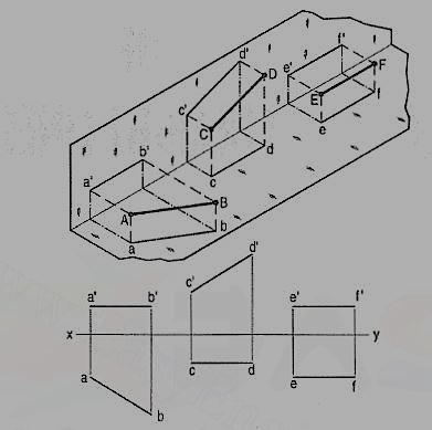
(a) Line AB is parallel to the H.P.
a and b are the top views of the ends A and B respectively. It can be clearly seen that the figure ABba is a rectangle. Hence, the top view ab is equal to AB.
a'b' is the front view of AB and is parallel to xy.
(b) Line CD is parallel to the V.P. The line c'd' is the front view and is equal to CD; the top view cd is parallel to xy.
(c) Line ff is parallel to the H.P. And the V.P. Ef is the top view and e'f' is the front view; both are equal to ff and parallel to xy.
Hence, when a line is parallel to a plane, its projection on that plane is equal to its true length; while its projection on the other plane is parallel to the reference line.
Line contained by one or both the planes:
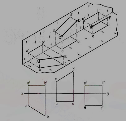
Line AB is in the H.P. Its top view ab is equal to AB; its front view a' b' is in xy.
Line CD is in the V.P. Its front view c'd' is equal to CO; its top view cd is in xy.
Line ff is in both the planes. Its front view e' f' and the top view ef coincide with each other in xy.
Hence, when a line is contained by a plane, its projection on that plane is equal to its true length; while its projection on the other plane is in the reference line.
Line perpendicular to one of the planes:
When a line is perpendicular to one reference plane, it will be parallel to the other.
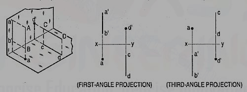
(a) Line AB is perpendicular to the H.P. The top views of its ends coincide in the point a. Hence, the top view of the line AB is the point a. Its front view a' b' is equal to AB and perpendicular to xy.
(b) Line CD is perpendicular to the V.P. The point d' is its front view and the line cd is the top view. Cd is equal to CD and perpendicular to xy.
Hence, when a line is perpendicular to a plane its projection on that plane is a point; while its projection on the other plane is a line equal to its true length and perpendicular to the reference line.
In first-angle projection method, when top views of two or more points coincide, the point which is comparatively farther away from xy in the front view will be visible; and when their front views coincide, that which is farther away from xy in the top view will be visible.
In third-angle projection method, it is just the reverse. When top views of two or more points coincide the point, which is comparatively nearer xy in the front view will be visible; and when their front views coincide, the point which is nearer xy in the top view will be visible.
Line inclined to one plane and parallel to the other:

The inclination of a line to a plane is the angle which the line makes with its projection on that plane.
Line PQ1 is inclined at an angle 8 to the H.P. And is parallelto the V.P. The inclination is shown by the angle 8 which PQ1 makes with its own projection on the H.P., viz. The top view pq1.
The projections may be drawn by first assuming the line to be parallel to both the H.P. And the V.P. Its front view p'q' and the top view pq will both be parallel to xy and equal to the true length. When the line is turned about the end P to the position PQ1 so that it makes the angle 8 with the H.P. While remaining parallel to the V.P., in the front view the point q' will move along an arc drawn with p' as center and p'q' as radius to a point q'1 so that p'q'1 makes the angle 8 with xy. In the top view, q will move towards p along pq to a point q1 on the projector through q'1. p'q'1 and pq1 are the front view and the top view respectively of the line PQ1.
Line inclined to both the planes:
A line AB is inclined at θ to the H.P. And is parallel to the V.P. The end A is in the H.P. AB is shown as the hypotenuse of a right-angled triangle, making the angle θ with the base.
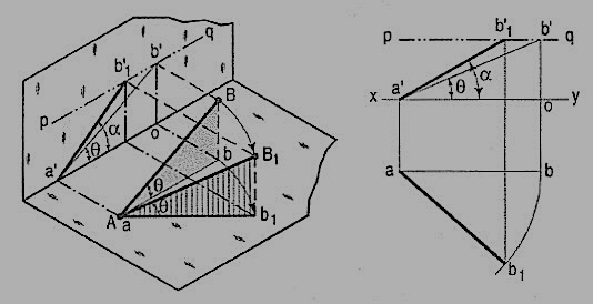
The top view ab is shorter than AB and parallel to xy. The front view a'b' is equal to AB and makes the angle θ with xy.
Keeping the end, A fixed and the angle θ with the H.P. Constant, if the end B is moved to any position, say B1, the line becomes inclined to the V.P. Also.
In the top view, b will move along an arc, drawn with a as center and ab as radius, to a position b1. The new top view ab1 is equal to ab but shorter than AB.
In the front view, b' will move to a point b'1 keeping its distance from xy constant and equal to b'o; i.e. it will move along the line pq, drawn through b' and parallel to xy. This line pq is the locus or path of the end B in the front view. b'1 will lie on the projector through b1. The new front view a'b'1 is shorter than a'b' (i.e. AB) and makes an angle a with xy. As is greater than θ.
Thus, if the inclination θ of AB with the H.P.is constant, even when it is inclined to the V.P.
(i) its length in the top view, viz. Ab remains constant; and
(ii) the distance between the paths of its ends in the front view, viz. b'o remains constant.
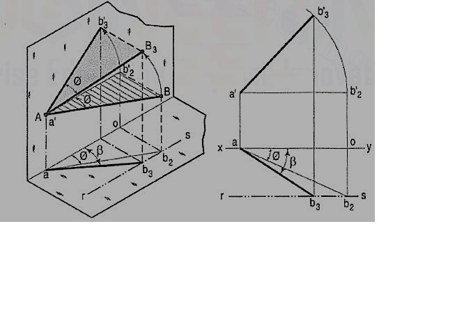
b) The same line AB is inclined at ϕ to the V.P. And is parallel to the H.P. Its end A is in the V.P. AB is shown as the hypotenuse of a right-angled triangle making the angle ϕ with the base.
The front view a'b'2 is shorter than AB and parallel to xy. The top view ab2 is equal to AB and makes an angle ϕ with xy.
Keeping the end, A fixed and the angle ϕ with the V.P. Constant, if B is moved to any position, say B3, the line will become inclined to the H.P. Also.
In the front view, b'2, will move along the arc, drawn with a' as center and a'b'2 as radius, to a position b'3. The new front view a'b'3 is equal to a'b'2 but is shorter than AB.
In the top view, b2 will move to a point b3 along the line rs, drawn through b2 and parallel to xy, thus keeping its distance from the path of a, viz. b2o constant. Rs is the locus or path of the end B in the top view. The point b3 lies on the projector through b'3. The new top view ab3 is shorter than ab2 (i.e. AB) and makes an angle β with xy. β is greater than ϕ.
Here also we find that, if the inclination of AB with the V.P. Does not change, even when it becomes inclined to the H.P.
(i) its length in the front view, viz. a'b'2 remains constant; and
(ii) the distance between the paths of its ends in the top view, viz. b2o remains constant.
Hence, when a line is inclined to both the planes, its projections are shorter than the two length and inclined to xy at angles greater than the true inclinations. These angles viz. α and β are called apparent angles of inclination.
Traces of a line:
When a line is inclined to a plane, it will meet that plane, produced if necessary. The point in which the line or line-produced meets the plane is called its trace.
The point of intersection of the line with the H.P. Is called the horizontal trace, usually denoted as H.T. And that with the V.P. Is called the vertical trace or V.T.
(i) A line AB is parallel to the H.P. And the V.P. It has no trace.
(ii) A line CD is inclined to the H.P. And parallel to the V.P. It has only the H.T. But no V.T.
(iii) A line ff is inclined to the V.P. And parallel to the H.P. It has only the V.T. But no H.T.

Thus, when a line is parallel to a plane it has no trace upon that plane.

(i) A line PQ is perpendicular to the H.P. Its H.T. Coincides with its top view which is a point. It has no V.T.
(ii) A line RS is perpendicular to the V.P. Its V.T. Coincides with its front view which is a point. It has no H.T.
Hence, when a line is perpendicular to a plane, its trace on that plane coincides with its projection on that plane. It has no trace on the other plane.
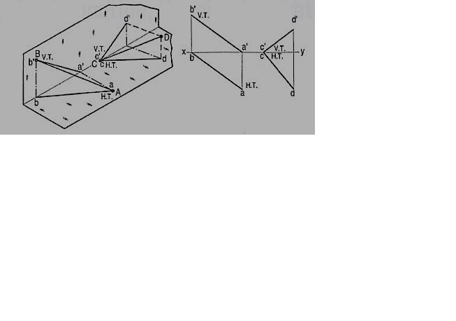
(i) A line AB has its end A in the H.P. And the end B in the V.P. Its H.T. Coincides with the top view of A and the V.T. Coincides with b' the front view of B.
(ii) A line CD has its end C in both the H.P. And the V.P. Its H.T. And V.T. Coincide with c and c' (the projections of C) in xy. Hence, when a line has an end in a plane, its trace upon that plane coincides with the projection of that end on that plane.
Methods of determining traces of a line:
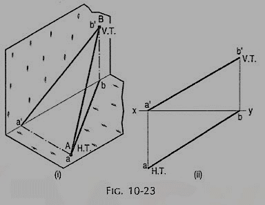
Method I:
a line AB inclined to both the reference planes. Its end A is in the H.P. And 8 is in the V.P. a'b' and ab are the front view and the top view respectively.
The H.T. Of the line is on the projector through a' and coincides with a. The V.T. Is on the projector through b and coincides with b'.
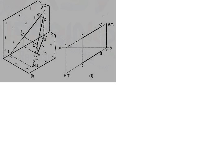
Let us now assume that AB is shortened from both its ends, its inclination with the planes remaining constant. The H.T. And V.T. Of the new line CD are still the same as can be seen clearly. c'd' and cd are the projections of CD. Its traces may be determined as described below.
(i) Produce the front view c'd' to meet xy at a point h.
(ii) Through h, draw a projector to meet the top view cd-produced, at the H.T. Of the line.
(iii) Similarly, produce the top view cd to meet xy at a point v.
(iv) Through v, draw a projector to meet the front view c'd'-produced, at the V.T. Of the line.
Method II:
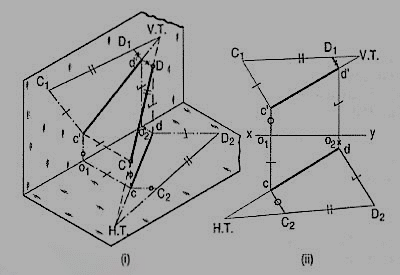
c'd' and cd are the projections of the line CD . Determine the true length C1D1 from the front view c'd' by trapezoid method. The point of intersection between c'd'-produced and C1D1-produced is the V.T. Of the line.
Similarly, determine the true length C2D2 from the top view ed. Produce them to intersect at the H.T. Of the line.
Examples:
1. A line AB 50 mm long, has its end A in both the H.P. And the V.P. It is inclined at 30° to the H.P. And at 45° to the V.P. Draw its projections.
As the end A is in both the planes, its top view and the front view will coincide in xy.
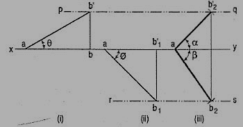
(i) Assuming AB to be parallel to the V.P. And inclined at θ (equal to 30°) to the H.P., draw its front view ab' (equal to AB) and project the top view ab.
(ii) Again, assuming AB to be parallel to the H.P. And inclined at ϕ (equal to 45°) to the V.P., draw its top view ab1 (equal to AB). Project the front view ab'1.
Ab and ab'1 are the lengths of AB in the top view and the front view respectively, and pq and rs are the loci of the end B in the front view and the top view respectively.
(iii) With a as center and radius equal to ab'1, draw an arc cutting pq in b'2. With the same center and radius equal to ab, draw an arc cutting rs in b2.
Draw lines joining a with b'2 and b2. Ab'2 and ab2 are the required projections.
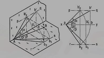
This shows in pictorial and orthographic views, the solution obtained with all the above steps combined in one figure only.