UNIT-1
ELECTROMAGNETIC WAVES AND DIELECTRICS
GRADIENT OF SCALAR FIELD
The gradient is a fancy word for derivative, or the rate of change of a function. It’s a vector (a direction to move) that
- Points in the direction of greatest increase of a function
- Is zero at a local maximum or local minimum (because there is no single direction of increase)
The term "gradient" is typically used for functions with several inputs and a single output (a scalar field). Yes, you can say a line has a gradient (its slope), but using "gradient" for single-variable functions is unnecessarily confusing. Keep it simple.
“Gradient” can refer to gradual changes of colour, but we’ll stick to the math definition. You’ll see the meanings are related.
PROPERTIES OF THE GRADIENT
Now that we know the gradient is the derivative of a multi-variable function, let’s derive some properties.
The regular, plain-old derivative gives us the rate of change of a single variable, usually x. For example, dF/dx tells us how much the function F changes for a change in x. But if a function takes multiple variables, such as x and y, it will have multiple derivatives: the value of the function will change when we “wiggle” x (dF/dx) and when we wiggle y (dF/dy).
We can represent these multiple rates of change in a vector, with one component for each derivative. Thus, a function that takes 3 variables will have a gradient with 3 components:
- F(x) has one variable and a single derivative: dF/dx
- F(x,y,z) has three variables and three derivatives: (dF/dx, dF/dy, dF/dz)
The gradient of a multi-variable function has a component for each direction.
And just like the regular derivative, the gradient points in the direction of greatest increase.
However, now that we have multiple directions to consider (x, y and z), the direction of greatest increase is no longer simply “forward” or “backward” along the x-axis, like it is with functions of a single variable.
If we have two variables, then our 2-component gradient can specify any direction on a plane. Likewise, with 3 variables, the gradient can specify and direction in 3D space to move to increase our function.
Gradient tells you how much something changes as you move from one point to another (such as the pressure in a stream). The gradient is the multidimensional rate of change of a particular function. The gradient vector is a representative of such vectors which present the value of differentiation in all the 360° direction for the given point on the curve”
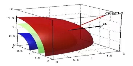
The gradient is a vector function which operates on a scalar function to produce a vector whose scale is the maximum rate of change of the function at the point of the gradient and which is pointed in the direction of that utmost rate of change. The symbol for the gradient is ∇.
Figure 1: Gradient |
(i) A gradient of a scalar quantity is a Vector quantity.
(ii) The magnitude of that vector quantity is equal to the Maximum rate of change of that scalar quantity.
(iii) Change of scalar quantity does not depend only on the coordinate of the point, but also on the direction along which the change is shown.
For the gradient of a vector field, you can think of it as the gradient of each component of that vector field individually, each of which is a scalar. The gradient always points in the direction of the maximum rate of change in a field.
PHYSICAL SIGNIFICANCE OF GRADIENT
A scalar field may be represented by a series of level surfaces each having a stable value of scalar point function θ.
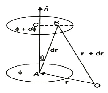
The θ changes by a stable value as we move from one surface to another. These surfaces are known as Gaussian surfaces. Now let the two such surfaces are very close together, be represented by two scalar point functions and (θ + d θ). Let ‘r’ and (r + d θ) be the position vectors of points A and B, on the surfaces θ and (θ + d θ) correspondingly with respect to an origin 0 as shown in Figure 2. Clearly, the vector AB will be dr. Let the least detachment between the two surfaces ‘dn’ be in the direction of unit usual vector n at A.
Figure 2: Physical significance of gradient |
dn = dr cos θ = | n | dr | cos θ =n .dr Dϕ = ∂ϕ/ dn =∂ϕ/dn n .dr…… (1) Since the continuous scalar function defining the level surfaces (Gaussian surfaces) has a value θ at point A (x, y, z) and (θ + dθ) at point (x + dx, y + dy, z + dz), we have dϕ = ∂ ϕ/dx dx +dϕ/∂y + ∂ϕ/∂x dz = (I ∂ϕ/∂x +j ∂ϕ/vy +k ∂ϕ/∂z) .(idx +jdy +kdz) = ∆ ϕ. dr … … (2) From equations (1) and (2), equating the values of d θ, We obtain ∆θ .dr =∆ ϕ= ∂ϕ/ ∂n n .dr As dr is an arbitrary vector, we have ∆ϕ =∂ϕ/∂ n Grad ϕ = ∂ ϕ/∂n n |
Therefore, the gradient an of a scalar field at any point is a vector field, the scale of which is equal to the highest rate of increase of θ at that point and the direction of it is similar as that of usual to the level surface at that point.
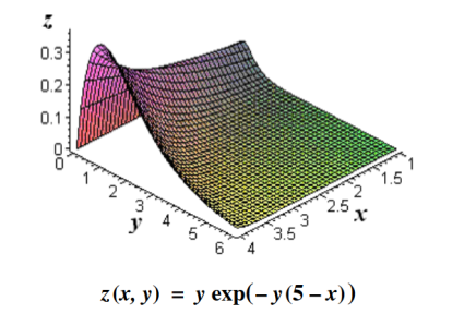
Its physical significance of grad can be understand in terms of the graph of some function z = f(x, y), where f is a reasonable function – say with continuous first partial derivatives. In this case we can think of the graph as a surface whose points have variable heights over the xy – plane. An illustration is given below.
Figure 3: Graph of a surface whose points have variable heights over the xy – plane. |
If, say, we place a marble at some point (x, y) on this graph with zero initial force, its motion will trace out a path on the surface, and in fact it will choose the direction of steepest descent. This direction of steepest descent is given by the negative of the gradient of f. One takes the negative direction because the height is decreasing rather than increasing.
Using the language of vector fields, we may restate this as follows: For the given function f(x, y), gravitational force defines a vector field F over the corresponding surface z = f(x, y), and the initial velocity of an object at a point (x, y) is given mathematically by –∇f(x, y). The gradient also describes directions of maximum change in other contexts. For example, if we think off as describing the temperature at a point(x, y), then the gradient gives the direction in which the temperature is increasing most rapidly.
DIVERGENCE AND CURL OF VECTOR FIELD
Divergence and curl are two measurements of vector fields that are very useful in a variety of applications. Both are most easily understood by thinking of the vector field as representing a flow of a liquid or gas; that is, each vector in the vector field should be interpreted as a velocity vector.
Divergence measures the tendency of the fluid to collect or disperse at a point, and curl measures the tendency of the fluid to swirl around the point. Divergence is a scalar, that is, a single number, while curl is itself a vector. The magnitude of the curl measures how much the fluid is swirling, the direction indicates the axis around which it tends to swirl.
DIVERGENCE
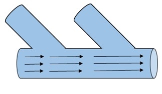
Consider water flowing through a large pipe. Now, it has smaller pipes joined to it. Hence, as the water flows, more water is added along the way by the smaller pipes. Hence, the mass flow rate increases as the water flows.
Figure 4: Water pipe |
In another case, consider that there is a leakage in the pipe. Hence the mass flow rate decreases as it flows. This change in the flow rate through the pipe, whether it increases or decreases, is called as divergence. Divergence denotes only the magnitude of change and so, it is a scalar quantity. It does not have a direction.
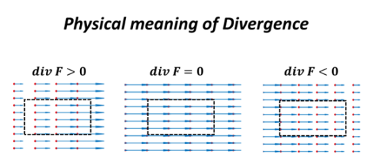
When the initial flow rate is less than the final flow rate, divergence is positive (divergence > 0). If the two quantities are same, divergence is zero. If the initial flow rate is greater than the final flow rate divergence is negative (divergence <0).
Recall that if f is a function, the gradient of f is given by
∇f=⟨∂f/∂x, ∂f/∂y, ∂f/∂z⟩
Where
∇ =⟨∂/∂x, ∂/∂y, ∂/∂z⟩
The divergence can be defined in terms of this same odd vector ∇ by using the dot product. The divergence of a vector field F=⟨f,g,h⟩ is
|
Figure 5: Physical interpretation of the divergence |
PHYSICAL INTERPRETATION OF THE DIVERGENCE
For an electric field:∇·E= ρ/ε, that is there are sources of electric field. Consider a vector field F that represents a fluid velocity: The divergence of F at a point in a fluid is a measure of the rate at which the fluid is flowing away from or towards that point.
A positive divergence is indicating a flow away from the point. ƒ Physically divergence means that either the fluid is expanding or that fluid is being supplied by a source external to the field. ƒ The lines of flow diverge from a source and converge to a sink.
If there is no gain or loss of fluid anywhere then div F= 0. Such a vector field is said to be solenoidal.
Air leaving a punctured tire: Divergence is positive, as closed surface (tire) exhibits net outflow.
CURL
Imagine pouring water in a cup. The water won’t just low linearly but rather, as it reaches the end of the cup, it will flow in a rotational motion before settling in the cup. Or consider water draining down the sink, it will swirl in a rotational motion before going out. If we plot this rotational flow of water as vectors and measure it, it will denote the Curl.
Figure 6: curl |
Curl is a measure of how much a vector field circulates or rotates about a given point. when the flow is counter-clockwise, curl is considered to be positive and when it is clock-wise, curl is negative. Sometimes, curl isn’t necessarily flow around a single time. It can also be any rotational or curled vector.
For example, curl can help us predict the voracity, which is one of the causes of increased drag. By using curl, we can calculate how intense it is and reduce it effectively. Calculating divergence helps us understand the flow rate and correct it to suit our needs.
The curl can be defined in terms of this same odd vector ∇ by using the cross product. The curl of a vector field F=⟨f,g,h⟩ is
|
PHYSICAL INTERPRETATION OF THE CURL
Consider a vector field F that represents a fluid velocity:
The curl of F at a point in a fluid is a measure of the rotation of the fluid.
If there is no rotation of fluid anywhere then ∇x F= 0. Such a vector field is said to be irrotational or conservative.
An electrostatic field (denoted by E) has the property ∇ x E= 0, an irrotational (conservative) field.
Key Takeaways
7. The curl can be defined in terms of this same odd vector ∇ by using the cross product. The curl of a vector field F=⟨f,g,h⟩ is
|
In dielectric material molecules are tightly bounded to the nucleus and not able to move freely as in case of conductor. But when a dielectric material is placed in an electric field, electric charges do not flow through the material as they flow in case of an electrical conductor but only slightly shift from their average equilibrium positions causing dielectric polarization. Because of dielectric polarization, positive charges are displaced in the direction of the field and negative charges shift in the direction opposite to the field. In dielectric molecules are tightly bound to the nucleus and not able to move freely as in case of conductors. The dielectric material is largely used in the manufacturing of capacitor.
Response of Dielectric to External Electric Field
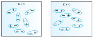
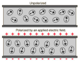
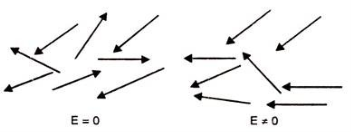
In case of Polar Molecules -When the electric field is not present, it causes the electric dipole moment of these molecules in a random direction. This is why the average dipole moment is zero. If the external electric field is present, the molecules align themselves in the direction electric field and resulted in having dipole moment.
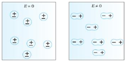
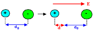
In case of Non-Polar Molecules – As we know nonpolar molecule has zero dipole moment. In spite of zero dipole, when a dielectric nonpolar material is placed in an electric field. The positive and the negative charges in a nonpolar molecule experience forces in opposite directions. This force causes the separation between the charges and hence nonpolar molecule experiences induced dipole moment.
Figure 7(a): (left) Non Polar Molecule Figure 7(b): (right) Polar Molecule |
In previous section we have seen about the dielectric material’s behaviour and we have seen that when the dielectric material is placed in an electric field, then the molecule of polar and non-polar dielectric gains the dipole moment. Then the dielectric is said to be polarised.
Definition:
The diploe moment per unit volume of dielectric material is called the electric polarization of dielectric. It is represented by vector P.
In S.I. system, unit of polarization is C/m2.
When an external electric field is applied to a dielectric material, its behaviour can be determined and is known as Dielectric Polarization that can be understood by the displacement of charges (positive and negative) when an electric field is applied
The main task of the dielectric polarization is to relate macroscopic properties to microscopic properties. Where macroscopic property can be dielectric constant to polarizability.
Polarization occurs through the action of an electric field or other external factors, such as mechanical stress in the case of piezoelectric crystals (piezoelectric crystals are those solid materials which accumulates electric charge within them). Dielectric Polarization can also arise spontaneously in pyroelectric crystals, particularly in ferroelectrics (Ferroelectricity is a property of certain materials that have a spontaneous electric polarization that can be reversed by the application of an external electric field).
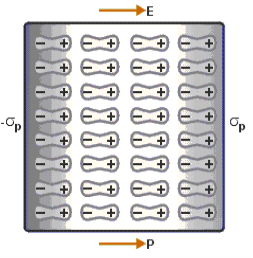
Figure 8: polarisation of dielectric molecules |
Above figure explains the polarisation of dielectric molecules when the electric field is applied.
Dielectric polarization occurs when a dipole moment is formed in an insulating material because of an externally applied electric field. When a current interacts with a dielectric material, the dielectric material will respond with a shift in charge distribution with the positive charges aligning with the electric field and the negative charges aligning against it.
Key Takeaways
- A dielectric is non-conducting material which stores electrical charges.
- The molecules of a dielectric is of two types Polar molecules and Non-polar molecules
- The diploe moment per unit volume of dielectric material is called the electric polarization of dielectric. It is represented by vector P. In S.I. system, unit of polarization is C/m2.
"When a dielectric material placed in external electrical field, it's molecule gain electric dipole moment and dielectric said to be polarised"
"The induce moment per unit volume of dielectric material is called the electric polarization of dielectric." It is represented by vector p.
Type of dielectric polarization
There are four types of dielectric polarization
1. Electronic polarization
2. Ionic polarization
3. Orientational polarization
4. Space charge polarization
1. Electric Polarization
Electronic polarization refers to the separation of centre of positive charge and centre of negative charge in a material.This separation is caused by high electric field.
|
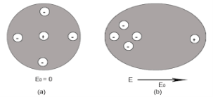
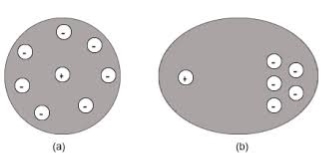
Figure 9: (a) shows thecharge distribution of an atom in absence of electric field while figure (b) show the charge distribution in presence of external electrical field.
Let us consider a single atom of atomic number Z. +e coulomb is the charge of each proton in the nucleus and -e coulomb is the charge of each electron surrounds the nucleus. All electrons in the atom form a spherical cloud of negative charge surrounds the positively charged nucleus. The charge of nucleus is +Ze coulombs and charge of the negative cloud of electrons is -Ze coulombs.
Let us also assume that the negative charge of the electrons cloud is homogeneously distributed on a sphere of radius R. In the absence of external electric field, the center of this sphere and center of nucleus of the atom coincide.
When an external electric field E is applied to the atom. Because of this external electric field the nucleus of the atom is shifted towards negative intensity of the field and the electron cloud is shifted towards the positive intensity of the field.
As due to influence of external electric field the center of nucleus and center of electrons cloud are separated, there will be an attractive force between them according to Coulomb’s law.
Let us suppose x is distance of separation between positive charge nucleus and electron cloud.
Also Nucleus is considered as point charge. Hence, the electrostatic force acting on the nucleus =+EZe …….(1)
As we know nucleus has been shifted from the center of electrons cloud by a distance x.
By using Gauss’s theorem
The force is only due to electron cloud acting upon nucleus would only be due to the portion of the cloud enclosed by the sphere of radius x. portion outside the sphere of radius x does not apply any force on the nucleus. Volume of the sphere of radius x = (4/3)πx3 and Volume of the sphere of radius R = (4/3)πR3 Now total negative charge of the electron cloud is -Ze …..(2) Hence, the quantity of negative charge enclosed by the sphere of radius x is, [-Ze/(4/3)πR3] * (4/3)πx3 = -Ze (x3/ R3) ……..(3) According to coulomb’s law = q1q2 /4 πR2 Charge on nucleus q2= Ze So coulomb’s force = {-Ze (x3/ R3) * Ze}/4πƐox2 = Z2e2x/4πƐo R3 ……(4) Note- magnitude is taken into account. Neglect negative sign. i.e. At equilibrium Electrostatic force = Coulomb force . EZe = Z2e2x/4πƐoR3 ……..(5) Upon simplify x = {4πƐoR3/Ze} E Now dipole moment = either charge * separation between charges i.e. x = Ze *{4πƐoR3/Ze} E = 4πƐoR3E Polarization is number of dipole moment per unit volume. Let us suppose N is the number of dipoles per unit volume so Pe=4πƐoR3EN So it is clear that polarization depends upon radius of atom or volume of atom and number of atoms present per unit volume. |
2. Ionic polarization
Ionic polarization occurred only in that dielectric material in which atoms contain ionic bonds. When such a material is placed in an external electric field the separation between positive charge and negative charge is separated through larger distance as compared to original length.
NaCl and KCl molecule shows ionic polarization occurs. In this polarization the net electric field is zero.
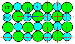
Sodium chloride (NaCl) molecule is formed by ionic bond between sodium and chlorine atoms. Due to electrostatic force between positive sodium and negative chlorine ions, they bound together and form sodium chloride molecule. Because of the presence of inter nucleus distance in the sodium chloride molecule, one might think that an ionic crystal would possess polarization even in the absence external electric filed. Since each pair constitute an electric dipole. But this is not so due to lattice symmetry these dipoles cancel each other’s effect.
Figure 10: NaCl crystal |
As NaCl have only two atoms or ions there must be a single dipole moment pointing from negative to positive ion in each molecule. But there exists other ionic compounds having more than two atoms.
Number of dipole moments is directly proportional to the number of bonds in a molecule. But all the dipole moments are directed from relatively negative ion to positive ion. The resultant dipole moment of a single molecule would be the vector sum of individual dipole moments of the molecule.
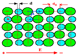
In absence of electric field E, the distance between the ions is d but in presence of electric field, distances between the ions increases.
Figure 11: NaCl in the presence of electric field |
In the presence of electric field we have certain amount of dipole moment.
Figure 12: Dipole moment |
Hence force F1 due to electric field is
F1=qE ……(1) Where q is the net charge on ion. F2 restoring force due to binding force between ions F2=kd …..(2) Where k is spring constant. Here we are considering bond as spring. k may also expressed in terms of other constant which is related to the shape of interatomic potential as young’s modulus or modulus of rigidity as k=Ydo …..(3) At Equilibrium F1 = F2 at equilibrium distance d qE = kd qE = Ydod using (3) d = Now dipole moment p= qd = q2E/Ydo …..(4) and polarization Pi = Nq2E / Ydo ……(5) This is called ionic polarization. This can also be expressed as Pi =NαiE Where αi is constant of proportionality known as ionic polarizability constant. This polarization is independent of temperature. |
3. Orientational Polarization
Polar dielectric exhibit orientational polarization. In the absence of electric field, the orientation of the molecule are random and hence the net dipole moment is zero when external force is applied the dipole tried to align themselves along the direction of the applied field. This type of polarization is known as orientational polarization.
Ionic polarization: Orientational polarization: This occurs due to the permanent dipole moment in a material. It occurs in elements such as HCl and H2O.
Figure 13: Orientational Polarization |
Potential energy U of the dipole moment making an angle θ with the electric field. Where p0 is the dipole moment. U=−p0⋅E=−p0Ecosθ According to statistical mechanics, the number of dipoles or molecules making an angle with the electric field is proportional to e−U/kT Letting n(θ) be the number of molecules per unit solid angle at θ, we have n(θ)=n0e+p0Ecosθ/kT
For normal temperatures and fields, the exponent is small, so we can approximate by expanding the exponential:
n(θ)= n0 (1+p0EcosθkT) To find n0 , we integrate over all angles and the result is equal to N. Where N is the total number of molecules per unit volume. The average value of cosθ over all angles is zero, so the integral is just n0 times the total solid angle 4π. We get n0=N4π or N= n0 /4π There exits molecules along the field (cosθ=1) than against the field (cosθ=−1). So in any small volume containing many molecules there will be a net dipole moment per unit volume. As dipole moment is present so polarization Pd is given
Pd =∑unitvolumep0cosθi
Evaluate Total Polarization over solid angle 2πsinθdθ. We have to integrate it
Pd = 0∫π n(θ)p0cosθ2πsinθdθ
Substitute the value of n(θ)
Pd = −N/2 −1∫1 {1+(p0E/kT)cosθ)p0cosθd(cosθ)
By integrating we get,
Pd =Np02E/ 3kT
The polarization is proportional to the field E and depends inversely on the temperature, because at higher temperatures there is more randomness by collisions. This can also be expressed as Pd =αdE Where αd is called dipolar or orientation polarizability and it is equal to p02/ 3kT.
|
4. Space Charge Polarization
space charge occurs due to accumulation of charge at the electrodes are at the interface in the multiphase material as shown in the figure. the ions diffuse over the appreciable distance in response to the applied field. this gives the rise of redistribution of charges in the dielectric medium
Figure 14: Space Charge Polarization
|
Space charge polarization is also known as Interfacial polarization. Space charge polarization occurs when there is an accumulation of charge at an interface between two materials or between two regions within a material because of an external field.
Space charge polarization can occur when there is a compound dielectric, or when there are two electrodes connected to a dielectric material. This type of electric polarization is different from orientational and ionic polarization because instead of affecting bound positive and negative charges i.e. ionic and covalent bonded structures, interfacial polarization also affects free charges as well.
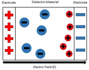
Interfacial polarization is usually observed in amorphous or polycrystalline solids. Figure 15 shows an example of how free charges can accumulate in a field, causing interfacial polarization.
The electric field will cause a charge imbalance because of the dielectric material's insulating properties. However, the mobile charges in the dielectric will migrate over maintain charge neutrality. This then causes interfacial polarization.
|
Figure 15: This shows how the free positive charges inside the dielectric material migrate towards the negative charge build-up on the right, caused by the external electric field.
The equation to show the space charge polarizability constant is
αc=α - α∞- α0 …………(1) |
where αc is the space charge polarizability and α, α∞, and α0 refer to the total, electronic, and orientational polarizations respectively.
It is important to note that because the charges are free charges, defects such as grain boundaries or other interfaces can serve as a medium for interfacial polarizability to form.
From the equation of space charge polarization, it is then determined that the total amount of dielectric polarization in a material is the sum of the electronic, orientational, and interfacial polarizabilities,
or
α=αc+α∞+α0
Key Takeaways
- There are four types of dielectric polarization 1. Electronic polarization 2. Ionic polarization 3. Orientational polarization 4. Space charge polarization
- Electronic polarization refers to the separation of centre of positive charge and centre of negative charge in a material.This separation is caused by high electric field.
- Polarization is number of dipole moment per unit volume. Let us suppose N is the number of dipoles per unit volume so Pe=4πƐoR3EN.
- Ionic polarization occurred only in that dielectric material in which atoms contain ionic bonds.
- Ionic polarization. Pi = Nq2E / Ydo can also be expressed as Pi =NαiE Where αi is constant of proportionality known as ionic polarizability constant.
- Polar dielectric exhibit orientational polarization. In the absence of electric field, the orientation of the molecule are random and hence the net dipole moment is zero when external force is applied the dipole tried to align themselves along the direction of the applied field. This type of polarization is known as orientational polarization.
- Space charge occurs due to accumulation of charge at the electrodes are at the interface in the multiphase material
Displacement current is the rate of change of electric displacement field.
The type of current which passes through a conductor is known as conduction current and is caused by the actual movement of electrons through the conductor. This type of current is mostly used in our day to day life. There is also another kind of current, which is known as displacement current. Displacement current differs from the conduction current because the displacement current does not involve electrons' movement. The displacement current has enormous importance for the propagation of electromagnetic waves. In electromagnetism, displacement current is a quantity appearing in Maxwell's equations that is defined in terms of the rate of change of electric displacement field.
Displacement current has the units of electric current density, and it has an associated magnetic field just as actual currents do.
It is mathematically represented as ID = JD S = S Where S = Area of the plate of the capacitor ID = Displacement current JD = Displacement current density D = εE where ε is permittivity of the medium During the charging and discharging process of the capacitor, the electric current flows through the wires of the circuit. However, no current flow between the plates of the capacitor. Derivation According to Ampere's law, the magnetic field should not present between the plates as there is no current, but in reality, the magnetic field exists there. Maxwell formulated this limitation of Ampere's law by adding a term in the equation of Ampere's law to solve the issue. Maxwell predicted that the magnetic field will still exist even in the absence of conduction current, and the magnetic field may be associated with the changing electric field. This theory of Maxwell was experimentally proved. Ampere's Law tells us that a flowing electric current gives rise to a magnetic field that circles the wire. In addition to this, it also says that an Electric Field that is changing in time gives rise to a magnetic field that encircles the E-field - this is the Displacement Current term that Maxwell himself introduced. This means there are 2 ways to generate a solenoidal (circulating) H-field - a flowing electric current or a changing Electric Field. Both give rise to the same phenomenon. The modified form of ampere Law is given by H.dL=(J+dD/dt) Take integration on both sides we have ∫H.dL=∫(J+dD/dt).dS Apply stoke’s theorem to L.H.S. of above equation, we get ∫( ∇xH).dS=∫ H.dL Now the above equation is written as ∫( ∇xH).dS =∫(J+dD/dt).dS By cancelling the surface integral on both sides we have ∇xH =J+dD/dt Which is the differential form of Maxwell’s equation. This can also be written in the form B The Ampere-Maxwell Law
Begin with the Ampere-Maxwell law in integral form.
Set the equation to 0.
Since the magnetic field is associated with the electric field, the general displacement current formula is given by, ∇ This equation is the generalized formula of Maxwell-Ampere law. Displacement Current Definition The displacement current (ID or D) is the part which Maxwell has added to the Ampere's law. ID = ε0 ε0 = Permittivity of free space The Maxwell equation can be written as ∇ |
Key Takeaways
- Displacement current is the rate of change of electric displacement field.
- Displacement current differs from the conduction current because the displacement current does not involve electrons' movement.
- The displacement current has enormous importance for the propagation of electromagnetic waves.
- Displacement current has the units of electric current density, and it has an associated magnetic field just as actual currents do.
- According to Ampere's law, the magnetic field should not present between the plates as there is no current, but in reality, the magnetic field exists there.
- There are 2 ways to generate a solenoidal (circulating) H-field - a flowing electric current or a changing Electric Field. Both give rise to the same phenomenon.
Maxwell equations are of fundamental importance since they describe the whole of classical electromagnetic phenomena. From a classical perspective, light can be described as waves of electromagnetic radiation. As such, Maxwell equations are very useful to illustrate a number of the characteristics of light including polarization. We are just to stating these equations without derivation. Since our goal is simply to apply them, the usual approach will be followed. Maxwell’s four equations are given by ∇·E = ρ/ε0 (1) ∇×E = −∂B/∂t (2) ∇×H = J + ∂D/∂t (3) ∇·B = 0 (4) These equations illustrate the unique coexistence in nature of the electric field and the magnetic field. The first two equations give the value of the given flux through a closed surface, and the second two equations give the value of a line integral around a loop. In this notation, ∇=(∂/∂x, ∂/∂y, ∂/∂z) E is the electric vector B is the magnetic induction ρ is the electric charge density j is the electric current density ε0 is the permittivity of free space c is the speed of light.
In addition to Maxwell equations, the following identities are useful:
J = σE (5) D = εE (6) B = μH (7)
Here, D is the electric displacement H is the magnetic vector σ is the specific conductivity ε is the dielectric constant (or permittivity) μ is the magnetic permeability In the Gaussian systems of units, Maxwell equations are given in the form of ∇·B=0 (8) ∇·E=4πρ (9) ∇×H=(1/c)(∂D/∂t+4πj) (10) ∇×E=−(1/c)(∂B/∂t) (11)
Free space or non-conducting medium. We know that non conducting medium means no current so conductivity is zero i.e. σ=0 So current density J=σE will also become zero as σ=0 Also free space means no charges which leads to ρ=0. These points mentioned below. (a) No condition current i.e σ=0, thus J=0 ( J=σE) (b) No charges (i.e ρ=0) For the case of no charges or currents, that is, j = 0 and ρ = 0, and a homogeneous medium. Using these the Maxwell equation can rewritten as ∇.D=0 or ∇.E=0 as ρ=0 (12) ∇ x E= -dB/dt or ∇ x E= -μ dH/dt because B = μH (13) ∇ x H=d D/dt or ∇ x H = ε dE/dt (J=0) and D = εE (14) ∇.B=0 (15) Maxwell's Equations are a set of 4 complicated equations that describe the world of electromagnetics. These equations describe how electric and magnetic fields propagate, interact, and how they are influenced by objects. Maxwell was one of the first to determine the speed of propagation of electromagnetic (EM) waves was the same as the speed of light - and hence to conclude that EM waves and visible light were really the same thing. These equations are rules the universe uses to govern the behaviour of electric and magnetic fields. A flow of electric current will produce a magnetic field. If the current flow varies with time (as in any wave or periodic signal), the magnetic field will also give rise to an electric field. Maxwell's Equations shows that separated charge (positive and negative) gives rise to an electric field - and if this is varying in time as well will give rise to a propagating electric field, further giving rise to a propagating magnetic field. From a classical perspective, light can be described as waves of electromagnetic radiation. As such, Maxwell equations are very useful to illustrate a number of the characteristics of light including polarization. The First Maxwell’s equation (Gauss’s law for electrostatics) Gauss' Law is the first of Maxwell's Equations which dictates how the Electric Field behaves around electric charges. Gauss' Law can be written in terms of the Electric Flux Density and the Electric Charge Density as: ∇·E = ρ/ε0 0r ∇·D = ρ
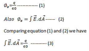
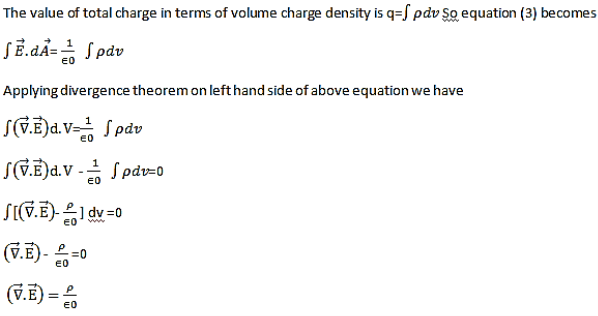
Hence, Gauss' law is a mathematical statement that the total Electric Flux exiting any volume is equal to the total charge inside. Hence, if the volume in question has no charge within it, the net flow of Electric Flux out of that region is zero. If there is positive charge within a volume, then there exists a positive amount of Electric Flux exiting any volume that surrounds the charge. If there is negative charge within a volume, then there exists a negative amount of Electric Flux exiting (i.e. the Electric Flux enters the volume). The Gauss’s law states that flux passing through any closed surface is equal to 1/ε0 times the total charge enclosed by that surface. Integral form of Maxwell’s 1st equation
Maxwell’s first equation in differential form It is called the differential form of Maxwell’s 1st equation.
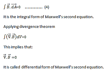
The Second Maxwell’s equation (Gauss’s law for magnetism) The Gauss’s law for magnetism states that net flux of the magnetic field through a closed surface is zero because monopoles of a magnet do not exist.
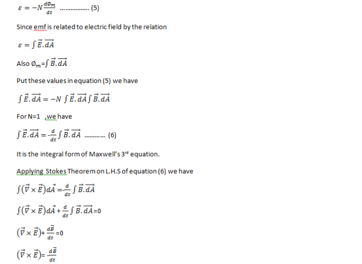
we know that Gauss' Law for Electric Fields states that the divergence of the Electric Flux Density D is equal to the volume electric charge density. But the second equation, Gauss' Magnetism law states that the divergence of the Magnetic Flux Density (B) is zero. Why? Why isn't the divergence of B equal to the magnetic charge density? Well - it is. But it just so happens that no one has ever found magnetic charge - not in a laboratory or on the street or on the subway. And therefore, until this hypothetical magnetic charge is found, we set the right side of Gauss' Law for Magnetic Fields to zero: ∇·B = 0 Now, you may have played with magnets when you were little, and these magnetic objects attracted other magnets similar to how electric charges repel or attract like electric charges. However, there is something special about these magnets - they always have a positive and negative end. This means every magnetic object is a magnetic dipole, with a north and South Pole. No matter how many times you break the magnetic in half, it will just form more magnetic dipoles. Gauss' Law for Magnetism states that magnetic monopoles do not exist - or at least we haven't found them yet. Maxwell’s Third equation (Faraday's Law) Faraday figured out that a changing Magnetic Flux within a circuit (or closed loop of wire) produced an induced EMF, or voltage within the circuit. Maxwell gives his second equation from this. Faraday's Law tells us that a magnetic field that is changing in time will give rise to a circulating E-field. This means we have two ways of generating E-fields - from Electric Charges (or flowing electric charge, current) or from a magnetic field that is changing. ∇×E = −∂B/∂t According to Faraday’s law of electromagnetic induction
Maxwell’s fourth equation (Ampere's Law) Ampere's Law tells us that a flowing electric current gives rise to a magnetic field that circles the wire. In addition to this, it also says that an Electric Field that is changing in time gives rise to a magnetic field that encircles the E-field - this is the Displacement Current term that Maxwell himself introduced. This means there are 2 ways to generate a solenoidal (circulating) H-field - a flowing electric current or a changing Electric Field. Both give rise to the same phenomenon. The modified form of ampere Law is given by H.dL=(J+dD/dt) Take integration on both sides we have ∫H.dL=∫(J+dD/dt).dS Apply stoke’s theorem to L.H.S. of above equation, we get ∫( ∇xH).dS=∫ H.dL Now the above equation is written as ∫( ∇xH).dS =∫(J+dD/dt).dS By cancelling the surface integral on both sides we have ∇xH =J+dD/dt Which is the differential form of Maxwell’s equation. This can also be written in the form B The Ampere-Maxwell Law
Begin with the Ampere-Maxwell law in integral form.
Invoke Stokes' theorem.
Set the equation to 0. |
Physical Significance Of Each Equation Physical significance of Maxwell’s Ist equation ∇·E = ρ/ε0 According to this total electric flux through any closed surface is 1/0 times the total charge enclosed by the closed surfaces, representing Gauss's law of electrostatics, As this does not depend on time, it is a steady state equation. Here for positive , divergence of electric field is positive and for negative divergence is negative. It indicates that is scalar quantity. Physical significance of Maxwell’s 2nd equation ∇·B = 0 It represents Gauss law of magnetostatic as ∇·B = 0 resulting that isolated magnetic poles or magnetic monopoles cannot exist as they appear only in pairs and there is no source or sink for magnetic lines of forces. It is also independent of time i.e. steady state equation. Physical significance of Maxwell’s 3rd equation ∇×E = −∂B/∂t It shows that with time varying magnetic flux, electric field is produced in accordance with Faraday is law of electromagnetic induction. This is a time dependent equation. Physical significance of Maxwell’s 4th equation ∇×H = J + ∂D/∂t This is a time dependent equation which represents the modified differential form of Ampere's circuital law according to which magnetic field is produced due to combined effect of conduction current density and displacement current density. |
Key Takeaways
- The First Maxwell’s equation is known as Gauss’s law for electrostatics. It is given by ∇·E = ρ/ε0 . According to this total electric flux through any closed surface is 1/0 times the total charge enclosed by the closed surfaces, representing Gauss's law of electrostatics,
- The Second Maxwell’s equation is known as Gauss’s law for magnetism. . It is given by ∇·B = 0. The Gauss’s law for magnetism states that net flux of the magnetic field through a closed surface is zero because monopoles of a magnet do not exist.
- Maxwell’s Third equation is known as Faraday's Law. It is given by ∇×E = −∂B/∂t. Faraday figured out that a changing Magnetic Flux within a circuit (or closed loop of wire) produced an induced EMF, or voltage within the circuit.
- Maxwell’s fourth equation is known as Ampere's Law. It is given by ∇×H = J + ∂D/∂t . Ampere’s Law tells us that a flowing electric current give rise to a magnetic field that circles the wire. In addition to this, it also says that an Electric Field that is changing in time gives rise to a magnetic field that encircles the E-field - this is the Displacement Current.
Wave is nothing but a pattern of disturbance which propagates and carry energy with it. You can produce a wave on a rope by moving one end of the rope up and down. The wave produces on rope needs a medium to propagate and here medium is rope itself. This type of waves is known as mechanical waves. But in the case of Electromagnetic waves, they don't need a medium to propagate. Electromagnetic waves are waves that are created as a result of variations of electric field and a magnetic field. Or we can say that Electromagnetic waves are nothing but changing magnetic and electric fields. Electromagnetic waves are also known to be solutions of Maxwell's equations. And Maxwell's equations are the fundamental equations of electrodynamics. Electromagnetic waves can transmit energy and travel through a vacuum.
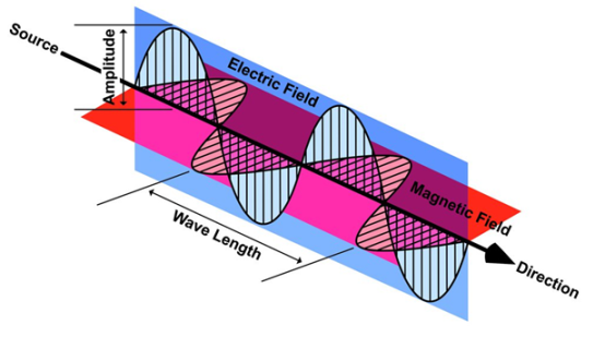
Light waves are examples of electromagnetic waves. Generally, Electromagnetic waves are shown by a sinusoidal graph.
Figure 16: Electromagnetic waves |
As shown in figure Electromagnetic waves consist of time-varying electric and magnetic fields and they are perpendicular to each other and these both fields are also perpendicular to the direction of propagation of waves.
Maxwell’s four equations are given by ∇·E = ρ/ε0 (1) ∇×E = −∂B/∂t (2) ∇×H = J + ∂D/∂t (3) ∇·B = 0 (4) These equations illustrate the unique coexistence in nature of the electric field and the magnetic field. The first two equations give the value of the given flux through a closed surface, and the second two equations give the value of a line integral around a loop. In this notation, ∇=(∂/∂x, ∂/∂y, ∂/∂z) E is the electric vector B is the magnetic induction ρ is the electric charge density j is the electric current density ε0 is the permittivity of free space c is the speed of light.
In addition to Maxwell equations, the following identities are useful:
J = σE (5) D = εE (6) B = μH (7)
Here, D is the electric displacement H is the magnetic vector σ is the specific conductivity ε is the dielectric constant (or permittivity) μ is the magnetic permeability Free space or non-conducting medium. We know that non conducting medium means no current so conductivity is zero i.e. σ=0 So current density J=σE will also become zero as σ=0 Also free space means no charges which leads to ρ=0. These points mentioned below. (a) No condition current i.e σ=0, thus J=0 ( J=σE) (b) No charges (i.e ρ=0) For the case of no charges or currents, that is, j = 0 and ρ = 0, and a homogeneous medium. Using these the Maxwell equation can rewritten as ∇.D=0 or ∇.E=0 as ρ=0 (12) ∇ x E= -dB/dt or ∇ x E= -μ dH/dt because B = μH (13) ∇ x H=d D/dt or ∇ x H = ε dE/dt (J=0) and D = εE (14) ∇.B=0 (15) |
WAVE EQUATION IN TERMS OF ELECTRIC FIELD INTENSITY, E Now taking curl of second Maxwell’s equation (13) ,we get ∇ x(∇ x E)=- μ d/dt (∇ x H) Applying standard vector identity, that is [∇ *(∇*E)=∇(∇.E)-∇2E] on left hand side of above equation, we get ∇ (∇ .E)-∇2E= -μ d/dt (∇ x H) (16) Substituting equations (13) and (14) in equations (16) ,we get -∇2E= – με d/dt (dE/dt) Or ∇2E=με d 2 E/dT2 (17) Equation (17) is the required wave equation in terms of electric field intensity, E for free space . This is the law that E must obey. WAVE EQUATION IN TERMS OF MAGNETIC FIELD INTENSITY, H Take curl of fourth Maxwell’s equation (14) ,we get ∇x(∇xH)=ε d/dt(∇xE) Applying standard vector identity that is [∇*(∇*H)=∇ (∇.H)-∇2H] On left side of above equation , we get ∇(∇.H)-∇2H= ε d/dt(∇xE) (18) Substituting equations (14) and (13) in equation(18) ,we get -∇2H= – μεd/dt(dH/dt) Or ∇2H=με d2H/dt2 (19) Equations (19) is the required wave equation in terms of magnetic field intensity, H and this is the law that H must obey For vacuum μ=μ0 and ε=ε0, equations (17) and (19) will become ∇2 E=μ0ε0 d2E/dt2 (20) And ∇2H= μ0ε0 d2H/dt2 (21) This leads to an expression for the velocity of propagation From equation both equations (20) and (21) have the form of the general wave equation for a wave
(x,t) traveling in the x direction with speed v. Equating the speed with the coefficients, we derive the speed of electric and magnetic waves, which is a constant that we symbolize with “c” It is useful to note that in vacuum c2=1/ε0μ0 Where μ0 is the permeability of free space
Let us rewrite the equation (20) and (21) for one dimension. Or d 2 E/dx2 = μ0ε0 d 2 E/dt2 (22) d2H/dx2 = μ0ε0 d2H/dt2 (23) The simplest solutions to the differential equations (22) and (23) are sinusoidal wave functions: E(x) = Emax cos(kx-t) (24) B(x) = Bmax cos(kx-t) (25) where k = 2π/λ is the wavenumber , ω = 2πƒ is the angular frequency, λ is the wavelength, f is the frequency and ω /k=f=v= c.
|
Key Takeaways
- Wave is nothing but a pattern of disturbance which propagates and carries energy with it.
- In the case of Electromagnetic waves, they don't need a medium to propagate. Electromagnetic waves are waves that are created as a result of variations of electric field and a magnetic field.
- Electromagnetic waves are also known to be solutions of Maxwell's equations.
- Wave equation in terms of electric field intensity E for free space is given by ∇2 E=μ0ε0 d2E/dt2
- Wave equation in terms of magnetic field intensity H for free space is given by ∇2H= μ0ε0 d2H/dt2
- (x,t) traveling with speed c in free space is given by

When electromagnetic wave travels in space, it carries energy and energy density is always associated with electric fields and magnetic fields.
The rate of energy travelled through per unit area i.e. the amount of energy flowing through per unit area in the perpendicular direction to the incident energy per unit time is called Poynting vector.
Mathematically Poynting vector is represented as
|
The direction of Poynting vector is perpendicular to the plane containing  and
and  . Poynting vector is also called as instantaneous energy flux density. Here rate of energy transfer
  is perpendicular to both
  and
and . It represents the rate of energy transfer per unit area.
UNIT
Its unit is W/m2.
Poynting Theorem
Poynting theorem states that the net power flowing out of a given volume V is equal to the time rate of decrease of stored electromagnetic energy in that volume decreased by the conduction losses.
i.e. total power leaving the volume =Rate of decrease of stored electromagnetic energy – ohmic power dissipated due to motion of charge
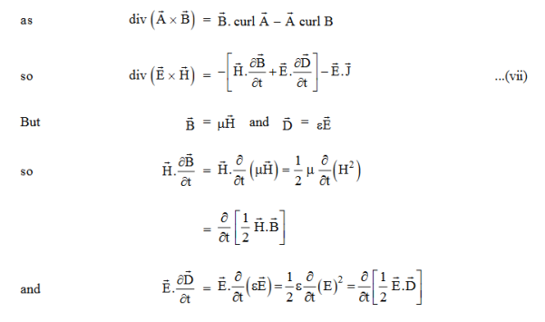
Proof The energy density carried by the electromagnetic wave can be calculated using Maxwell's equations div div Curl Curl Taking scalar product of (3) with H and (4) with i.e. and Doing (vi) – (v) i.e.
So from equation (vii)
Or
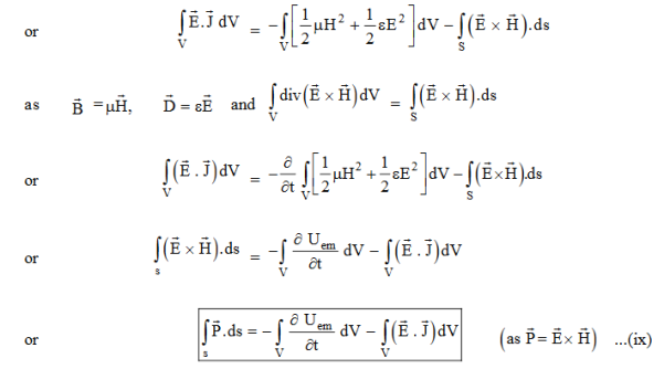
Integrating equation (viii) over a volume V enclosed by a Surface S
|
Total power leaving the volume = rate of decrease of stored e.m. energy -ohmic power dissipated due to charge motion
This equation (ix) represents the Poynting theorem according to which the net power flowing out of a given volume is equal to the rate of decrease of stored electromagnetic energy in that volume minus the conduction losses.
In equation (ix)  .ds represents the amount of electromagnetic energy crossing the closed surface per second or the rate of flow of outward energy through the surface S enclosing volume V i.e. it is Poynting vector.
The term represent
the energy stored in electric and magnetic fields respectively and their sum denotes the total energy stored in electromagnetic field. So total terms gives the rate of decrease of energy stored in volume V due to electric and magnetic fields.
Gives the rate of energy transferred into the electromagnetic field. This is also known as work-energy theorem. This is also called as the energy conservation law in electromagnetism. |
Key Takeaways
- The rate of energy travelled through per unit area i.e. the amount of energy flowing through per unit area in the perpendicular direction to the incident energy per unit time is called Poynting vector.
- Mathematically Poynting vector is represented as
 =
=  =(
=(  )
) - The direction of Poynting vector is perpendicular to the plane containing
 and
and  .
. - Poynting vector is also called as instantaneous energy flux density. It represents the rate of energy transfer per unit area.
- Its unit is W/m2.
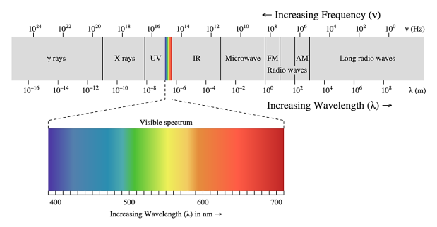
At the time Maxwell predicted the existence of electromagnetic waves, the only familiar electromagnetic waves were the visible light waves. The existence of ultraviolet and infrared waves was barely established. By the end of the nineteenth century, X-rays and gamma rays had also been discovered. We now know that, electromagnetic waves include visible light waves, X-rays, gamma rays, radio waves, microwaves, ultraviolet and infrared waves.
The classification of electromagnetic waves according to frequency is the electromagnetic spectrum.
There is no sharp division between one kind of wave and the next. The classification is based roughly on how the waves are produced and/or detected
Figure 17: Electromagnetic Spectrum |
We briefly describe these different types of electromagnetic waves, in order of decreasing wavelengths.
Radio waves: Radio waves are produced by the accelerated motion of charges in conducting wires. They are used in radio and television communication systems. They are generally in the frequency range from 500 kHz to about 1000 MHz. The AM (amplitude modulated) band is from 530 kHz to 1710 kHz. Higher frequencies upto 54 MHz are used for short wave bands. TV waves range from 54 MHz to 890 MHz. The FM (frequency modulated) radio band extends from 88 MHz to 108 M Hz. Cellular phones use radio waves to transmit voice communication in the ultrahigh frequency (UHF) band.
Microwaves: Microwaves (short-wavelength radio waves), with frequencies in the gigahertz (GHz) range, are produced by special vacuum tubes (called klystrons, magnetrons and Gunn diodes). Due to their short wavelengths, they are suitable for the radar systems used in aircraft navigation. Radar also provides the basis for the speed guns used to time fast balls, tennis-serves, and automobiles. Microwave ovens are an interesting domestic application of these waves. In such ovens, the frequency of the microwaves is selected to match the resonant frequency of water molecules so that energy from the waves is transferred efficiently to the kinetic energy of the molecules. This raises the temperature of any food containing water.
Infrared waves: Infrared waves are produced by hot bodies and molecules. This band lies adjacent to the low-frequency or long-wave length end of the visible spectrum. Infrared waves are sometimes referred to as heat waves. This is because water molecules present in most materials readily absorb infrared waves (many other molecules, for example, CO2, NH3, also absorb infrared waves). After absorption, their thermal motion increases, that is, they heat up and heat their surroundings. Infrared lamps are used in physical therapy. Infrared radiation also plays an important role in maintaining the earth’s warmth or average temperature through the greenhouse effect. Incoming visible light (which passes relatively easily through the atmosphere) is absorbed by the earth’s surface and re-radiated as infrared (longer wavelength) radiations. This radiation is trapped by greenhouse gases such as carbon dioxide and water vapour. Infrared detectors are used in Earth satellites, both for military purposes and to observe growth of crops. Electronic devices (for example semiconductor light emitting diodes) also emit infrared and are widely used in the remote switches of household electronic systems such as TV sets, video recorders and hi-fi systems.
Visible rays: It is the most familiar form of electromagnetic waves. It is the part of the spectrum that is detected by the human eye. It runs from about 4 × 10¹⁴ Hz to about 7 × 10¹⁴Hz or a wavelength range of about 700 –400 nm. Visible light emitted or reflected from objects around us provides us information about the world. Our eyes are sensitive to this range of wavelengths. Different animals are sensitive to different range of wavelengths. For example, snakes can detect infrared waves, and the ‘visible’ range of many insects extends well into the ultraviolet.
Ultraviolet rays: It covers wavelengths ranging from about 4 × 10⁻⁷ m (400 nm) down to 6 × 10⁻¹⁰m (0.6 nm). Ultraviolet (UV) radiation is produced by special lamps and very hot bodies. The sun is an important source of ultraviolet light. But fortunately, most of it is absorbed in the ozone layer in the atmosphere at an altitude of about 40 – 50 km. UV light in large quantities has harmful effects on humans. Exposure to UV radiation induces the production of more melanin, causing tanning of the skin. UV radiation is absorbed by ordinary glass. Hence, one cannot get tanned or sun burn through glass windows. Welders wear special glass goggles or face masks with glass windows to protect their eyes from large amount of UV produced by welding arcs. Due to its shorter wavelengths, UV radiations can be focussed into very narrow beams for high precision applications such as LASIK (Laser-assisted in situ keratomileusis) eye surgery. UV lamps are used to kill germs in water purifiers. Ozone layer in the atmosphere plays a protective role, and hence its depletion by chlorofluorocarbons (CFCs) gas (such as freon) is a matter of international concern.
X-rays: Beyond the UV region of the electromagnetic spectrum lies the X-ray region. We are familiar with X-rays because of its medical applications. It covers wavelengths from about 10–8 m (10 nm) down to 10–13 m(10–4 nm). One common way to generate X-rays is to bombard a metal target by high energy electrons. X-rays are used as a diagnostic tool in medicine and as a treatment for certain forms of cancer. Because X-rays damage or destroy living tissues and organisms, care must be taken to avoid unnecessary or over exposure.
Gamma rays: They lie in the upper frequency range of the electromagnetic spectrum and have wavelengths of from about 10–10m to less than 10–14m. This high frequency radiation is produced in nuclear reactions and also emitted by radioactive nuclei. They are used in medicine to destroy cancer cells.
Key Takeaways
- The classification of electromagnetic waves according to frequency is the electromagnetic spectrum.
- Radio waves are produced by the accelerated motion of charges in conducting wires. They are used in radio and television communication systems.
- Microwaves (short-wavelength radio waves), with frequencies in the gigahertz (GHz) range, are produced by special vacuum tubes.
- Infrared waves are produced by hot bodies and molecules.
- Visible light emitted or reflected from objects around us provides us information about the world.
- Ultraviolet (UV) radiation is produced by special lamps and very hot bodies.
- One common way to generate X-rays is to bombard a metal target by high energy electrons.
- Gamma rays radiation is produced in nuclear reactions and also emitted by radioactive nuclei.
Reference
- Prabir K. Basu & Hrishikesh Dhasmana, ‘Electromagnetic Theory’.
- Khunita, ‘Fundamentals of Electromagnetic Theory’.
- S.P. Puri, ‘Classical Electrodynamics’, Tata McGraw Hill
- Gupta & Gaur, ‘Engineering Physics’, Dhanpat Rai.
- Malik and Singh, ‘Engineering Physics’, Tata McGraw Hill.
- David Griffiths, ‘Introduction to Electrodynamics’.
