UNIT-1
ELECTROSTATICS IN VACUUM AND IN LINEAR DIELECTRIC MEDIUM
1.1.1 CHARGE DISTRIBUTION
We have seen so far, the charge distributions have been discrete i.e. made up of individual point particles.
If a charge distribution is continuous rather than discrete, we can generalize the definition of the electric field. We simply divide the charge into infinitesimal pieces and treat each piece as a point charge.
We know that charge is quantized so there is no such thing as a truly continuous charge distribution. However, in most practical cases, the total charge creating the field involves such a huge number of discrete charges.
For simplicity we can safely ignore the discrete nature of the charge and consider it to be continuous. This is exactly the kind of approximation we make when we deal with a bucket of water as a continuous fluid rather than a collection of H2O molecules.
Continuous charge distribution: an arrangement of many discrete charges so closely spaced that the charge is treated as a continuum, resulting in a replacement of discrete sums with integrals.
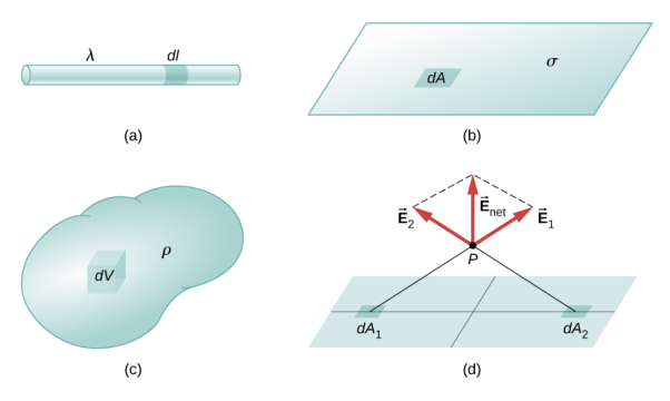
Distribution of charges
(a) Line charge density
(b) Surface charge density
(c) Volume charge density
(d) Some of the components of the total electric field cancel out, with the remainder resulting in a net electric field
Definitions of charge density:
(a) λ - Line charge: charge per unit length (linear charge density); units are coulombs per meter (C/m)
(b)  - Surface charge density: Charge per unit area; units are coulombs per square meter (C/m2)
(c)  - Volume charge density: Charge per unit volume; units are coulombs per cubic meter (C/m3)
|
Figure 1: Charge Distribution
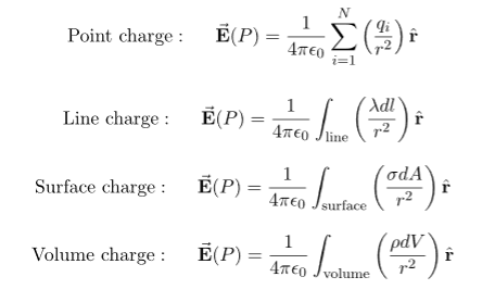
Some of the important result for electric field due to point charge, line charge density, surface charge density and volume charge density.
|
Note carefully the meaning of r in these equations: It is the distance from the charge element λdl,  ,
,  to the location of interest, P(x,y,z) (the point in space where you want to determine the field). However, don’t confuse this with the meaning of
  .
.
1.1.2 ELECTRIC FIELD AND ELECTROSTATIC POTENTIAL FOR A CONTINUOUS CHARGE DISTRIBUTION
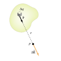
If the charge distribution is continuous, the potential at a point P can be found by summing over the contributions from individual differential elements of charge. dq
|
Figure 2: Continuous charge distribution
Consider the charge distribution shown in Figure. Taking infinity as our reference point with zero potential, the electric potential at P due to dq is
Summing over contributions from all differential elements, we have
We established the relation between dV = - In Cartesian coordinates, E = Ex and dV = ( Ex dV = ( Ex dx+ Eydy + Ezdz This implies Ex = By introducing a differential quantity called the “del (gradient) operator”
The electric field can be written as
Notice that ∇ operates on a scalar quantity (electric potential) and results in a vector quantity (electric field). Mathematically, we can think of In the case of gravity, if the gravitational potential increases when a mass is lifted a distance h, the gravitational force must be downward. If the charge distribution possesses spherical symmetry, then the resulting electric field is a function of the radial distance r, i.e. In this case, .dV=- Er dr. If V(r) is known, then
For example, the electric potential due to a point charge q is V = Using the above formula, the electric field is simply E = |
1.1.3 ELECTRIC FIELD OF A LINE SEGMENT OR ROD
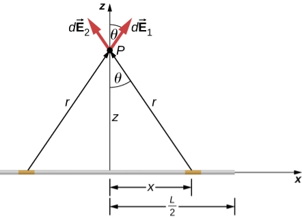
Let us find the electric field a distance z above the midpoint of a straight-line segment of length L that carries a uniform line charge density λ.
Since this is a continuous charge distribution, we conceptually break the wire segment into differential pieces of length dl, each of which carries a differential amount of charge dq = λdl.
We proceed as follow to obtain the complete electric field expression.
|
Figure 3: A uniformly charged segment of wire. The electric field at point P can be found by applying the superposition principle to symmetrically placed charge elements and integrating.
Since it is a finite line segment, from far away, it should look like a point charge. We will check the expression we get to see if it meets this expectation.
The electric field for a line charge is given by the general expression
The symmetry of the situation (our choice of the two identical differential pieces of charge) implies the horizontal (x)-components of the field cancel, so that the net field points in the The total field
Because the two charge elements are identical and are the same distance away from the point P where we want to calculate the field,
These components are also equal, so we have
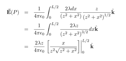
Here our differential line element dl is dx, in this example, since we are integrating along a line of charge that lies on the x-axis. The limits of integration are 0 to In principle, this is complete. However, to actually calculate this integral, we need to eliminate all the variables that are not given. In this case, both r and θ change as we integrate outward to the end of the line charge, so those are the variables to get rid of as follow r = and Cos θ = Substituting, we obtain
This simplifies to
With the use of symmetry, we are able to find electric field due to line element. This is a very common strategy for calculating electric fields. The fields of non-symmetrical charge distributions have to be handled with multiple integrals.
|
1.1.4 ELECTRIC FIELD OF AN INFINITE LINE OF CHARGE
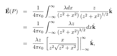
Find the electric field a distance z above the midpoint of an infinite line of charge that carries a uniform line charge density λ. This is exactly like the 1.12 article except the limits of integration will be - Again, the horizontal components cancel out, so we wind up with
Where our differential line element dl is dx, in this example, since we are integrating along a line of charge that lies on the x-axis. Again, Cos θ = Substituting, we obtain
This simplifies to
In the case of a finite line of charge, note that for z >>L, z2 dominates L the
If you recall that λL=q, the total charge on the wire, we have retrieved the expression for the field of a point charge, as expected. In the limit L
|
1.1.5 ELECTRIC FIELD DUE TO A RING OF CHARGE
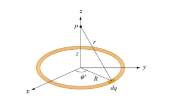
A ring has a uniform charge density λ, with units of coulomb per unit meter of arc. Find the electric potential at a point on the axis passing through the center of the ring.
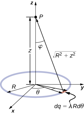
We use the same procedure as for the charged wire. The difference here is that the charge is distributed on a circle. We divide the circle into infinitesimal elements shaped as arcs on the circle and use polar coordinates shown in figure
|
Figure 4: The system and variable for calculating the electric field due to a ring of charge.
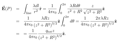
A general element of the arc between θ and dθ is of length Rdθ and therefore contains a charge equal to λRdθ. The element is at a distance of r = Cos And therefore, the electric field is
Significance As usual, symmetry simplified this problem, in this particular case resulting in a trivial integral. Also, when we take the limit of Z >> R, we find that
|
1.1.6 ELECTRIC POTENTIAL FOR UNIFORMLY CHARGED ROD
Electric Potential
Electric potential is the work done by an applied force on a unit charge bringing it from infinity to a specific point. The work done is called electric Potential.
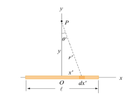
Consider a non-conducting rod of length A having a uniform charge density λ. Find the electric potential at P, a perpendicular distance y above the midpoint of the rod.
|
Figure 5: A non-conducting rod of length l and uniform charge density λ
Consider a differential element of length dx′ which carries a charge dq =λdx′, as shown in Figure. The source element is located at (x′,0) while the field point P is located on the y-axis at (0,y). The distance from dx′ to P is r = dV =
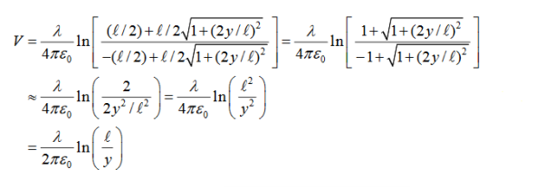
Taking V to be zero at infinity, the total potential due to the entire rod is
Where we have used the integration formula
In the limit the potential becomes l>>y
The corresponding electric field can be obtained as
|
1.1.7 ELECTRIC POTENTIAL FOR UNIFORMLY CHARGED RING
Uniformly consider a uniformly charged ring of radius R and charge density λ. electric potential at a distance z from the central axis
|
Figure 6: A non-conducting ring of radius R with uniform charge density λ
Consider a small differential element dl= Rd dq =λdl = λ and its contribution to the electric potential at P is
The electric potential at P due to the entire ring is
………….(2)
Where we have substituted Q=2πRλ for the total charge on the ring. In the limit z>>R, the potential approaches its “point-charge” limit:
From Equation 2, the z-component of the electric field may be obtained as
This is in agreement with the result of article 1.14 |
Key Takeaways
5. Electric field of an infinite line of charge
6. Electric field due to a ring of charge |
1.2.1 DIVERGENCE OF ELECTROSTATIC FIELD
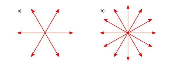
The electric field can be graphically represented using field lines. The direction of the field lines indicates the direction in which a positive test charge moves when placed in this field. The density of field lines per unit area is proportional to the strength of the electric field. Field lines originate on positive charges and terminate on negative charges. Field lines can never cross since if this would occur, the direction of the electric field at that particular point would be undefined. Examples of field lines produced by positive point charges are shown in Figure
|
Figure 7: a) Electric field lines generated by a positive point charge with charge q. b) Electric field lines generated by a positive point charge with charge 2q.
The flux of electric field lines through any surface is proportional to the number of field lines passing through that surface. Consider for example a point charge q located at the origin. The electric flux
Since the number of field lines generated by the charge q depends only on the magnitude of the charge, any arbitrarily shaped surface that encloses q will intercept the same number of field lines. Therefore the electric flux through any surface that encloses the charge q is equal to q/
We thus conclude that for an arbitrary surface and arbitrary charge distribution
where Qenclosed is the total charge enclosed by the surface. This is called Gauss's law. Since this equation involves an integral it is also called Gauss's law in integral form. Using the divergence theorem the electric flux
We can also rewrite the enclosed charge Qencl in terms of the charge density ρ
Gauss's law can thus be rewritten as
Since we have not made any assumptions about the integration volume this equation must hold for any volume. This requires that the integrands are equal:
This equation is called Gauss's law in differential form. This is the required expression for divergence of electric field. Divergence is the outflow of flux from a small closed surface area (per unit volume) as volume shrinks to zero. |
Physical Interpretation of the Divergence ƒ
For an electric field: ∇·E= ρ/ε, that is there are sources of electric field. Consider a vector field F that represents a fluid velocity: The divergence of F at a point in a fluid is a measure of the rate at which the fluid is flowing away from or towards that point.
A positive divergence is indicating a flow away from the point. ƒ Physically divergence means that either the fluid is expanding or that fluid is being supplied by a source external to the field. ƒ The lines of flow diverge from a source and converge to a sink.
If there is no gain or loss of fluid anywhere then div F= 0. Such a vector field is said to be solenoidal.
Air leaving a punctured tire: Divergence is positive, as closed surface (tire) exhibits net outflow.
1.2.2 CURL OF ELECTROSTATIC FIELD
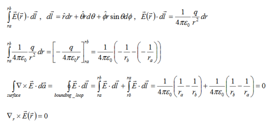
For a point charge q placing at the origin, the electric field is: E = The curl calculation by integration:
By superposition rule:
The curl calculation by differentiation:
|
Physical Interpretation of the Curl ƒ
Consider a vector field F that represents a fluid velocity:
The curl of F at a point in a fluid is a measure of the rotation of the fluid.
If there is no rotation of fluid anywhere then ∇x F= 0. Such a vector field is said to be irrotational or conservative.
An electrostatic field (denoted by E) has the property ∇xE= 0, an irrotational (conservative) field.
Key Takeaways
- The flux of electric field lines through any surface is proportional to the number of field lines passing through that surface.
- Divergence is the outflow of flux from a small closed surface area (per unit volume) as volume shrinks to zero.
- The curl of F at a point in a fluid is a measure of the rotation of the fluid.
1.3.1 LAPLACE’S AND POISSON’S EQUATIONS FOR ELECTROSTATIC POTENTIAL
A useful approach to the calculation of electric potentials is to relate that potential to the charge density which gives rise to it. The electric field is related to the charge density by the divergence relationship
E = Electric field
and the electric field is related to the electric potential by a gradient relationship E = Therefore the potential is related to the charge density by Poisson's equation
In a charge-free region of space, this becomes Laplace's equation
This mathematical operation, the divergence of the gradient of a function, is called the Laplacian. Expressing the Laplacian in different coordinate systems to take advantage of the symmetry of a charge distribution helps in the solution for the electric potential V. |
For example, if the charge distribution has spherical symmetry, you use the Laplacian in spherical polar coordinates.
Since the potential is a scalar function, this approach has advantages over trying to calculate the electric field directly. Once the potential has been calculated, the electric field can be computed by taking the gradient of the potential.
1.3.2 LAPLACE'S EQUATION IN ONE DIMENSION
In one dimension the electrostatic potential V depends on only one variable x. The electrostatic potential V(x) is a solution of the one-dimensional Laplace equation
The general solution of this equation is V(x) = sx + b where s and b are arbitrary constants. These constants are fixed when the value of the potential is specified at two different positions. |
Example
Consider a one-dimensional world with two point conductors located at x = 0 m and at x = 10 m. The conductor at x = 0 m is grounded (V = 0 V) and the conductor at x = 10 m is kept at a constant potential of 200 V. Determine V. V(0) = b = 0V and V(10) = 10s +b =200V The first boundary condition shows that b = 0 V. The second boundary condition shows that s = 20 V/m. The electrostatic potential for this system of conductors is thus V(x) = 20x E(x) = The boundary conditions used here, can be used to specify the electrostatic potential between x = 0 m and x = 10 m but not in the region x < 0 m and x > 10 m. If the solution obtained here was the general solution for all x, then V would approach infinity when x approaches infinity and V would approach minus infinity when x approaches minus infinity. The boundary conditions therefore provide the information necessary to uniquely define a solution to Laplace's equation, but they also define the boundary of the region where this solution is valid (in this example 0 m < x < 10 m). |
The following properties are true for any solution of the one-dimensional Laplace equation: V(x) is the average of V(x + R) and V(x - R) for any R as long as x + R and x - R are located in the region between the boundary points. This property is easy to proof:
This property immediately suggests a powerful analytical method to determine the solution of Laplace's equation. If the boundary values of V are V(x=a) =Va and V(x=b) =Vb then property 1 can be used to determine the value of the potential at (a + b)/2: Next we can determine the value of the potential at x = (3 a + b)/4 and at x = (a + 3 b)/4 :
This process can be repeated and V can be calculated in this manner at any point between x = a and x = b (but not in the region x > b and x < a).
Property 2: The solution of Laplace's equation cannot have local maxima or minima. Extreme values must occur at the end points (the boundaries). This is a direct consequence of property 1. Property 2 has an important consequence: a charged particle cannot be held in stable equilibrium by electrostatic forces alone (Earnshaw's Theorem). A particle is in a stable equilibrium if it is located at a position where the potential has a minimum value. A small displacement away from the equilibrium position will increase the electrostatic potential of the particle, and a restoring force will try to move the particle back to its equilibrium position. There can be no local maxima or minima in the electrostatic potential. The particle cannot be held in stable equilibrium by just electrostatic forces. |
1.3.3 LAPLACE'S EQUATION IN TWO DIMENSIONS
In two dimensions the electrostatic potential depends on two variables x and y. Laplace's equation now becomes
|
This equation does not have a simple analytical solution as the one-dimensional Laplace equation does. However, the properties of solutions of the one-dimensional Laplace equation are also valid for solutions of the two-dimensional Laplace equation:
Property 1: The value of V at a point (x, y) is equal to the average value of V around this point
where the path integral is along a circle of arbitrary radius, centered at (x, y) and with radius R. Property 2:
|
1.3.4 LAPLACE'S EQUATION IN THREE DIMENSIONS
In three dimensions the electrostatic potential depends on three variables x, y, and z. Laplace's equation now becomes
|
This equation does not have a simple analytical solution as the one-dimensional Laplace equation does. However, the properties of solutions of the one-dimensional Laplace equation are also valid for solutions of the three-dimensional Laplace equation:
Property 1:
Where the surface integral is across the surface of a sphere of arbitrary radius, centered at (x,y,z) and with radius R.
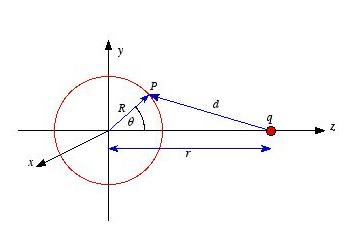
Figure 8: Laplace's equation in three dimensions
Proof of property 1. To proof this property of V consider the electrostatic potential generated by a point charge q located on the z axis, a distance r away from the center of a sphere of radius R . The potential at P, generated by charge q, is equal to
where d is the distance between P and q. Using the cosine rule we can express d in terms of r, R and θ
The potential at P due to charge q is therefore equal to Vp=
The average potential on the surface of the sphere can be obtained by integrating Vp across the surface of the sphere. The average potential is equal to
Which is equal to the potential due to q at the center of the sphere. Applying the principle of superposition it is easy to show that the average potential generated by a collection of point charges is equal to the net potential they produce at the center of the sphere. Property 2: |
Example: Problem 3.3
Find the general solution to Laplace's equation in spherical coordinates, for the case where V depends only on r. Then do the same for cylindrical coordinates.
If V is only a function of r then
and
Therefore, Laplace's equation can be rewritten as
The solution V of this second-order differential equation must satisfy the following first-order differential equation:
This differential equation can be rewritten as
V(r) = Where b is a constant. If V = 0 at infinity then b must be equal to zero, and consequently V(r)=
If V is only a function of r then
and
Therefore, Laplace's equation can be rewritten as
The solution V of this second-order differential equation must satisfy the following first-order differential equation: r This differential equation can be rewritten as
The general solution of this first-order differential equation is V(r) = aln(r) +b Where b is a constant. The constants a and b are determined by the boundary conditions.
|
Key Takeaways
8. For 3D - The electrostatic potential V has no local maxima or minima; all extremes occur at the boundaries. |
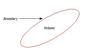
Consider a volume within which the charge density is equal to zero. Suppose that the value of the electrostatic potential is specified at every point on the surface of this volume. The first uniqueness theorem states that in this case the solution of Laplace's equation is uniquely defined.
|
Figure 9: First Uniqueness Theorem
To proof the first uniqueness theorem we will consider what happens when there are two solutions V1 and V2 of Laplace's equation in the volume shown in Figure. Since V1 and V2 are solutions of Laplace's equation we know that
Since both V1 and V2 are solutions, they must have the same value on the boundary. Thus V1 = V2 on the boundary of the volume. Now consider a third function V3, which is the difference between V1 and V2
The function V3 is also a solution of Laplace's equation. This can be demonstrated easily:
The value of the function V3 is equal to zero on the boundary of the volume since V1 = V2 there. However, property 2 of any solution of Laplace's equation states that it can have no local maxima or minima and that the extreme values of the solution must occur at the boundaries. Since V3 is a solution of Laplace's equation and its value is zero everywhere on the boundary of the volume, the maximum and minimum value of V3 must be equal to zero. Therefore, V3 must be equal to zero everywhere. This immediately implies that V1 = V2 |
This proves that there can be no two different functions V1 and V2 that are solutions of Laplace's equation and satisfy the same boundary conditions. Therefore, the solution of Laplace's equation is uniquely determined if its value is a specified function on all boundaries of the region. This also indicates that it does not matter how you come by your solution: if (a) it is a solution of Laplace's equation, and (b) it has the correct value on the boundaries, then it is the right and only solution.
|
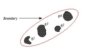
Figure 10: Boundary
The first uniqueness theorem can only be applied in those regions that are free of charge and surrounded by a boundary with a known potential (not necessarily constant). In the laboratory the boundaries are usually conductors connected to batteries to keep them at a fixed potential.
In many other electrostatic problems, we do not know the potential at the boundaries of the system. Instead, we might know the total charge on the various conductors that make up the system (note: knowing the total charge on a conductor does not imply a knowledge of the charge distribution ρ since it is influenced by the presence of the other conductors).
In addition to the conductors that make up the system, there might be a charge distribution ρ filling the regions between the conductors. For this type of system the first uniqueness theorem does not apply.
The second uniqueness theorem states that the electric field is uniquely determined if the total charge on each conductor is given and the charge distribution in the regions between the conductors is known.
The proof of the second uniqueness theorem is similar to the proof of the first uniqueness theorem.
Suppose that there are two fields
where ρ is the charge density at the point where the electric field is evaluated. The surface integrals of
The difference between
satisfies the following equations:
Consider the surface integral of Therefore, The surface integral of
Since the surface integral of the surface integral of
The surface integral
0 = = -
where the volume integration is over all space between the conductors and the outer surface. Since |
Key Takeaways
- The first uniqueness theorem states that in this case the solution of Laplace's equation is uniquely defined.
- The first uniqueness theorem can only be applied in those regions that are free of charge and surrounded by a boundary with a known potential (not necessarily constant).
- The second uniqueness theorem states that the electric field is uniquely determined if the total charge on each conductor is given and the charge distribution in the regions between the conductors is known.
It is a very powerful technique for solving electrostatics problems involving charges and conductors.
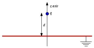
When a charge distribution is placed over an infinite ground plane Coulomb’s law and Gauss’s law cannot be readily applied.
Solving Poisson’s or Laplace’s equation is an option, but this is also mathematically challenging, likely to require a numerical solution
It turns out that an electrically equivalent problem can be created using the image distribution with the ground plane removed.
A simple example of a single point charge Q distanced above a ground plane is shown in Figure.
|
Figure 11: Electric field lines
Consider a point charge q held as a distance d above an infinite grounded conducting plane as shown in Figure The electrostatic potential of this system must satisfy the following two boundary conditions:
V(x,y,z) =0
|
Note: the charge distribution on the surface of a grounded conductor does not need to be zero.
|
Figure 12: Method of images
Consider a second system, consisting of two point charges with charges +q and -q, located at z = d and z = -d, respectively as shown in figure. The electrostatic potential generated by these two charges can be calculated directly at any point in space. At a point P = (x, y, 0) on the xy plane the electrostatic potential is equal to
Since this solution satisfies the boundary conditions, it must be the correct solution in the region z > 0 for the system shown in Figure. This technique of using image charges to obtain the electrostatic potential in some region of space is called the method of images. The electrostatic potential can be used to calculate the charge distribution on the grounded conductor. Since the electric field inside the conductor is equal to zero, the boundary condition for
Where σ is the surface charge density and
Only in the last step of this calculation have we substituted z = 0. The induced charge distribution is negative and the charge density is greatest at (x = 0, y = 0, z = 0). The total charge on the conductor can be calculated by surface integrating of σ:
where
As a result of the induced surface charge on the conductor, the point charge q will be attracted towards the conductor. Since the electrostatic potential generated by the charge image-charge system is the same as the charge-conductor system in the region where z > 0, the associated electric field (and consequently the force on point charge q) will also be the same. The force exerted on point charge q can be obtained immediately by calculating the force exerted on the point charge by the image charge. This force is equal to
There is however one important difference between the image-charge system and the real system. This difference is the total electrostatic energy of the system. The electric field in the image-charge system is present everywhere, and the magnitude of the electric field at (x, y, z) will be the same as the magnitude of the electric field at (x, y, -z).
On the other hand, in the real system the electric field will only be non-zero in the region with z > 0. Since the electrostatic energy of a system is proportional to the volume integral of Wimage = The electrostatic energy of the real system is therefore equal to Wreal = The electrostatic energy of the real system can also be obtained by calculating the work required to be done to assemble the system. In order to move the charge q to its final position we will have to exert a force opposite to the force exerted on it by the grounded conductor. The work done to move the charge from infinity along the z axis to z = d is equal to
Which is identical to the result obtained using the electrostatic potential energy of the image-charge system.
|
Key Takeaways
|
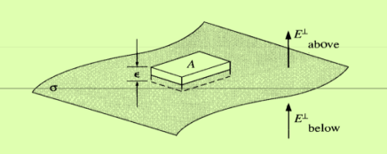
In solving some electrostatic problems dealing with some surface charge of density  , it’s found that the electric field undergoes a discontinuity as you cross the boundary. Understanding this boundary condition helps us to determine the electric field above some material with some surface charge. It allows us to determine the electric field even if external electric fields are present. The charge density could even vary on the surface. Now, what is the boundary condition? That is, by what amount is the electric field discontinuous across a charged surface?
We will use Gauss’s law which is:
|
Now we’ll take a surface of charge density  and surround a portion of the surface with a Gaussian “pillbox” of width
  and area A as shown in figure 13. Notice that it extends above and below the surface. Notice that both
  and
and  point up.
This is to say that upward is the positive direction and to account for the fact that we don’t know what the direction of E actually is. After all, as I said before, there could be an external field, and differences in charge density on the surface could alter the electric field in other areas. This also highlights something important about Gauss’s law. It means that E is not simply the field due to  .
.
In general, when we solve a problem and apply Gauss’s law, we are enclosing all the charge of the system to determine the electric field, and so E is due to the enclosed charge. But in this case, the electric field could be influenced by some outside source or other areas on the surface. What matters is that any outside electric fields contribute nothing to the flux.
|
Figure 13: Boundary Conditions
In the limit that  goes to zero, the sides of the pillbox contribute nothing to the flux. Because the flux is the contributions of
  , the flux gives us the electric field perpendicular to our Gaussian surface.
Most applications of Gauss’s law take advantage of symmetry so that the electric field is parallel to da and so that E is constant over the Gaussian surface.
In this case, we still want E to be constant across our Gaussian surface but E may not be parallel to da. So we must make our surface area small enough so that the field is constant. Since the perpendicular component of E is parallel to da, and we’ve taken an area small enough so that E is constant, we can take E outside the integral. This gives:
|
The minus sign comes from the fact that below the surface, da points downward. This means that as we cross the surface charge, the perpendicular component of the electric field will always have a discontinuity of .
.
Tangential component of the electric field
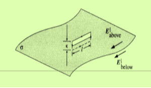
We can determine the tangential component by exploiting the path independence property of the electric field. We can make a path tangential to the surface on top that comes back around tangentially to the bottom as shown in figure 14.
|
Figure 14: Tangential component of the electric field
Now we use
The ends of the path have length
Again, the minus sign comes from the fact that dl points in different directions on the top and bottom. This means that:
So the tangential component is always continuous and therefore contributes nothing to the discontinuity of the total electric field. Combining the components then gives:
Where If we have two points, a below the surface and b below the surface, then the potential difference between the two points is:
As the distance of the path shrinks to zero, where we just cross the surface, then:
So the potential is continuous as we cross the surface. Since E =
Or
Where |
Key Takeaways
|
1.7.1 ELECTRIC FIELD DUE TO A DIPOLE
Case (i) Electric field due to an electric dipole at points on the axial line
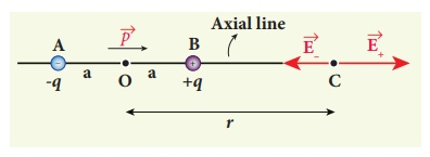
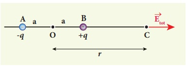
Consider an electric dipole placed on the x-axis as shown in Figure 15. A point C is located at a distance of r from the midpoint O of the dipole along the axial line.
|
Figure 15: Electric field of the dipole on the axial line
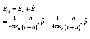
The electric field at a point C due to +q is
Since the electric dipole moment vector
where p ^ is the electric dipole moment unit vector from –q to +q. The electric field at a point C due to –q is
Since +q is located closer to the point C than –q, The total electric field at point C is calculated using the superposition principle of the electric field.
Note that the total electric field is along The direction of
Figure 16: Total electric field of the dipole on the axial line
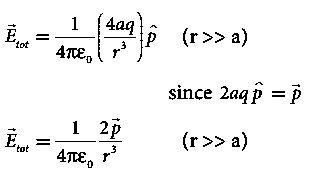
If the point C is very far away from the dipole then (r >> a). Under this limit the term ( r2 − a2 )2 ≈ r4 . Substituting this into equation (6), we get
If the point C is chosen on the left side of the dipole, the total electric field is still in the direction of
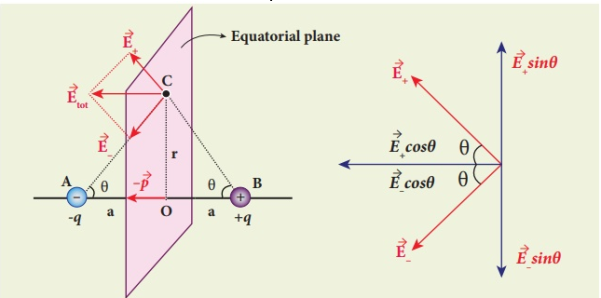
Case (ii) Electric field due to an electric dipole at a point on the equatorial plane Consider a point C at a distance r from the midpoint O of the dipole on the equatorial plane as shown in Figure 17. Since the point C is equidistant from +q and –q, the magnitude of the electric fields of +q and –q are the same. The direction of
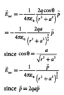
Figure 17: Electric field of the dipole at a point on the equatorial plane
The magnitudes
By substituting equation (9) into equation (8), we get
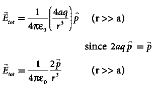
At very large distances (r>>a), the equation (10) becomes
|
Important inferences
(i) From equations (7) and (11), it is inferred that for very large distances, the magnitude of the electric field at points on the dipole axis is twice the magnitude of the electric field at points on the equatorial plane. The direction of the electric field at points on the dipole axis is directed along the direction of dipole moment vector  but at points on the equatorial plane it is directed opposite to the dipole moment vector, that is along -
 .
.
(ii) At very large distances, the electric field due to a dipole varies as 1/r3. Note that for a point charge, the electric field varies as 1/r2. This implies that the electric field due to a dipole at very large distances goes to zero faster than the electric field due to a point charge. The reason for this behaviour is that at very large distance, the two charges appear to be close to each other and neutralize each other.

 (iii) The equations (7) and (11) are valid only at very large distances (r>>a). Suppose the distance 2a approaches zero and q approaches infinity such that the product of 2aq = p is finite, then the dipole is called a point dipole. For such point dipoles, equations (7) and (11) are exact and hold true for any r.
1.7.2 POTENTIAL DUE TO AN ELECTRIC DIPOLE
We already know that electric dipole is an arrangement which consists of two equal and opposite charges +q and -q separated by a small distance 2a.
Electric dipole moment is represented by a vector p of magnitude 2qa and this vector points in direction from -q to +q.
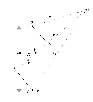
To find electric potential due to a dipole consider charge -q is placed at point P and charge +q is placed at point Q as shown below in the figure 18.
|
Figure 18: Potential due to an electric dipole
Since electric potential obeys superposition principle so potential due to electric dipole as a whole would be sum of potential due to both the charges +q and -q. Thus
Now draw line PC perpendicular to RO and line QD perpendicular to RO as shown in figure. From triangle POC
If we consider the case where r>>a then
Again since pcosθ= p·
From above equation we can see that potential due to electric dipole is inversely proportional to r2 not 1/r which is the case for potential due to single charge. Potential due to electric dipole does not only depend on r but also depends on angle between position vector r and dipole moment p.
|
Key Takeaways
2. Electric field due to an electric dipole at a point on the equatorial plane At very large distances (r>>a) given as
3. Potential due to an electric dipole given as
|
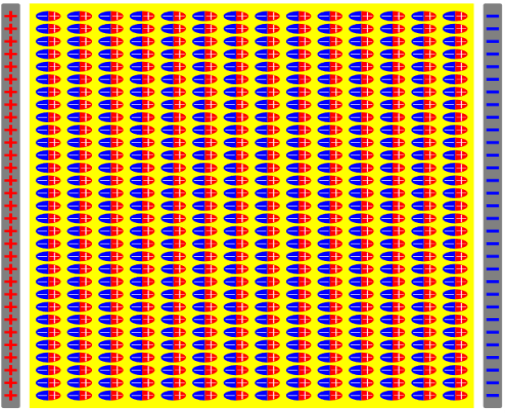
Any kind of matter is full of positive and negative electric charges. In a dielectric, these charges are bound— they cannot move separately from each other through any macroscopic distance, — so when an electric field is applied there is no net electric current. However, the field does push the positive charges just a tiny bit in the direction of E while the negative charges are pushed in the opposite directions. Consequently, the atoms and the molecules comprising the dielectric acquire tiny electric dipole moments in the direction of E.
|
Figure 19: Bound Charges Due to Electric Polarization
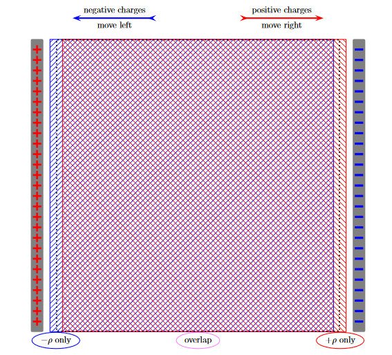
To see the net effect of all these dipole moments on the macroscopic scale, imagine smearing all the positive bound charges into a large uniform charge density +ρ and likewise all the negative bound charges into uniform charge density−ρ. Without the electric field, these densities overlap each other over the whole dielectric, so the net charge density cancels out. But when we turn on the field, the positive density moves a tiny bit in the direction of E while the negative density moves in the opposite direction:
|
Figure 20: Bound Charges Due to Electric Polarization
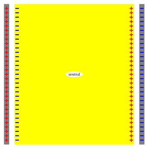
As the result of this move, the bulk of the dielectric — where the positive and negative charges continue to overlap each other — remains electrically neutral. But in a thin surface layer on the left side of the dielectric there are only negative charges, while in a similar layer on the right side there are only positive charges. Altogether, the dielectric’s surfaces acquire non-zero net densities σb of bound charges as shown in the figure 21 below:
|
Figure 21: Bound Charges Due To Electric Polarization
Now let’s turn from pictures to math and calculate the net surface density of the bound charges in terms of the polarization
P = net dipole moment /volume …………(1)
In general, the polarization is not uniform but varies on the macroscopic scale, maybe because the dielectric is non-uniform, maybe because it’s subject to a non-uniform electric field, maybe both.
In any case, mathematically the non-uniform P(r) acts as a macroscopic field. So let’s calculate the electric potential V(r) due to a general polarization field, and then reinterpret the result in terms of the bound charges.
Let’s start with the potential of a single ideal dipole,
Where the second equality is just the mathematical identity, ∇(−1/r) =
Where the subscript r of ∇r indicates that the gradient is taken with respect to the 3 coordinates of the r vector rather than of the r0. Eq. (3) easily generalizes to the potential of several dipole moments, and hence to the potential of a continuous density of the dipole moment, thus
Note that the gradient here is taken with respect to the r vector — the point where we measure the potential — rather than the with respect to the integration variable r′= (x′, y′, z′) However, since 1/|r−r′| depends only on the difference between the two position vectors, we may trade the gradient w.r.t. r for the (minus) gradient w.r.t. r′ using
Thus
At this point, the gradient acts on the integration variable, so we may integrate by parts using
and the Gauss theorem
…………(8) Note that both terms on the bottom line here look like Coulomb potentials of continuous charges. Specifically, the second term looks like the Coulomb potential of the volume charge density. ρb(r′) =−∇ ·P(r′) …………(9)
While the first term looks like the Coulomb potential of the surface charge density σb(r′) =P(r′)·n …………(10)
Where n is the unit vector normal to the dielectric’s surface at the point r′, hence P·d2A= (P·n)d2A=σbd2A. …………(11) Indeed, in terms of the ρb(r) and σb(r), eq. (8) becomes
Physically, we identify the σb=P·n as the net surface density of the bound charges and the ρb=−∇ ·P as the net volume density of the bound charges. Note: for general non-uniform polarizations P(r), the positive and the negative bound charge densities may mis-cancel not only on the surface of a dielectric but also inside its volume. However, for the uniform polarization there are no net volume bound charges but only the surface bound charges.
|
Key Takeaways
- The bulk of the dielectric — where the positive and negative charges continue to overlap each other — remains electrically neutral
- Any kind of matter is full of positive and negative electric charges. In a dielectric, these charges are bound— they cannot move separately from each other through any macroscopic distance,
- We identify the σb=P·n as the net surface density of the bound charges and the ρb=−∇ ·P as the net volume density of the bound charges.
- For general non-uniform polarizations P(r), the positive and the negative bound charge densities may mis-cancel not only on the surface of a dielectric but also inside its volume.
- For the uniform polarization there are no net volume bound charges but only the surface bound charges.
Besides the bound charges due to polarization, a dielectric material may also contain some extra charges which just happen to be there. For a lack of a better term, such extra charges are called free charges, just to contrast them from the bound charged due to polarization. Anyway, the net macroscopic electric field does not care for the origin of the electric charges or how we call them but only
In particular, the Gauss Law in differential form says
For simplicity, let's ignore for a moment the surface, line, and point charges and focus on just the volume charge density. This gives us
which we may rewrite as ∇.(ε0E+P) = In light of this formula, the combination D(r) =ε0E(r) +P(r) ………(4) called the electric displacement field obeys the Gauss Law involving only the free charges but not the bound charges, ∇.D(r) = |
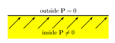
Outside the dielectric there is no polarization, so we simply set
D(r) =ε0E(r) ……(1) Consequently, at the dielectric’s boundary, the D field has two sources of discontinuity: (1) The abrupt disappearance of the P term, and (2) Discontinuity of the E field due to the net surface charge density. If we focus on the component of the D vector ⊥ to the boundary, we get disc (D⊥) =−Pinside⊥+ ε0disc(E⊥) =−P·n + σnet=−σbound + σnet=σfree ……(2) Again, only the free surface charge affects this discontinuity, the bound surface charge cancels out between the P and the ε0E terms. In terms of the D field's divergence, the discontinuity of ∇.(ε0E+P) = ( Similar ∇.D(r) = but only the free charges appear on the RHS here. All contributions of the bound charges cancel against the ∇.P term hiding inside the ∇.E on the LHS. Therefore, the integral form of the Gauss Law for the D field is
where the RHS includes all possible configurations of free charges surrounded by the surface S, but only the free charges. By the way, the surface S in this formula can be any complete surface | it can lie completely inside the dielectric, or completely outside it, or even cross the dielectric's surface | but the Gauss Law will work in any case, as long as we properly account for the net free charge enclosed within S. For highly symmetric cases, we may calculate the D field just from the Gauss Law; more general geometries do not allow such shortcuts. In fact, in general D(r) Indeed, while the electrostatic tension field (Electric Field) always obeys ∇ ∇ This issue becomes particularly acute at the dielectric's boundary. We know that despite the surface charge density of the bound charges, the potential and the tangential components of the electric tension field must be continuous across the boundary. V(just outside) =V(just inside) ……(7) E∥(just outside) =E∥(just inside) ……(8) On the other hand, the polarization field P abruptly drops to zero at the boundary, so if P just inside the dielectric is directed at some general angle to the surface, then both its tangential and normal components suffer discontinuities. P∥(just inside)
P⟂ (just inside)
Figure 22: Boundary Conditions On Displacement
Combining equations (9) and (10), we find that in general the tangential components of the displacement field are discontinuous across the dielectric's boundary, D∥(just outside) As to the normal components of the tension and the displacement fields, the E⟂ is generally discontinuous across the boundary due to surface bound charges, but as we saw in eq. (2), In the absence of free charges D⟂ (just outside) =D⟂ (just inside) ……….(12) In the middle of a dielectric or outside it: ∇.D= ∇ On the other hand, ∇.E= (1/ε0) ∇ At the outer boundary of a dielectric, or at the boundary between two different dielectrics
To complete this equation system, we need a relation between the E and the D fields at the same point r, and that relation depends very much on the dielectric material in question. For some material, such relation can be rather complicated, or even history-dependent. Fortunately, for most common dielectrics the relation between the E and the D fields is linear (unless the fields become too strong). So in this class, we shall hence forth focus on such linear dielectrics. |
Key Takeaways
- Outside the dielectric there is no polarization, so we simply set D(r) =ε0
- At the dielectric’s boundary, the D field has two sources of discontinuity: (1) The abrupt disappearance of the P term, and (2) Discontinuity of the E field due to the net surface charge density.
- the tangential components of the displacement field are discontinuous across the dielectric's boundary, D∥(just outside)
 D∥(just inside)
 - In the absence of free charges D⟂ (just outside) =D⟂ (just inside)
- At the outer boundary of a dielectric, or at the boundary between two different dielectrics: V, E∥, and D⟂ are continuous and E⟂ and D∥ are discontinuous.
References
1 David Griffiths, ‘Introduction to Electrodynamics’.
2 S.P. Puri, ‘Classical Electrodynamics’, Tata McGraw Hill
3 Gupta & Gaur, ‘Engineering Physics’, Dhanpat Rai.
4 Malik and Singh, ‘Engineering Physics’, Tata McGraw Hill.
5 Naidu, ‘Engineering Physics’, Pearson.
