UNIT-2
MAGNETOSTATICS AND MAGNETOSTATICS IN LINEAR MAGNETIC MEDIUM
The Biot Savart Law is an equation describing the magnetic field generated by a constant electric current. It relates the magnetic field to the magnitude, direction, length, and proximity of the electric current. Biot–Savart law is consistent with both Ampere’s circuital law and Gauss’s theorem. The Biot-Savart law is fundamental to magnetostatics, playing a role similar to that of Coulomb’s law in electrostatics. The Biot-Savart law can be stated as:
Where, k is a constant, depending upon the magnetic properties of the medium and system of the units employed. In the SI system of unit,
Therefore, the final Biot-Savart law derivation is,
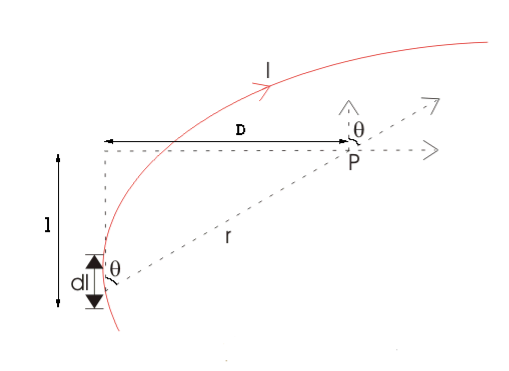
DERIVATION Let us consider a long wire carrying a current I and also consider a point p in the space. The wire is presented in the picture below, by red colour. Let us also consider an infinitely small length of the wire dl at a distance r from the point P as shown. Here, r is a distance-vector which makes an angle θ with the direction of current in the infinitesimal portion of the wire. If you try to visualize the condition, you can easily understand the magnetic field density at point P due to that infinitesimal length dl of the wire is directly proportional to current carried by this portion of the wire. As the current through that infinitesimal length of wire is the same as the current carried by the whole wire itself, we can write,
The magnetic field density at that point P due to that infinitesimal length dl of wire is inversely proportional to the square of the straight distance from point P to the center of dl. Mathematically we can write this as,
Figure 1: Biot-Savart law
As θ be the angle between distance vector r and direction of current through this infinitesimal portion of the wire, the component of dl directly facing perpendicular to the point P is dlsinθ,
Now, combining these three statements, we can write,
This is the basic form of Biot Savart’ s Law Now, putting the value of constant k (which we have already introduced at the beginning of this article) in the above expression, we get
Here, μ0 used in the expression of constant k is absolute permeability of air or vacuum and its value is 4π
Now, flux density(B) at the point P due to the total length of the current-carrying conductor or wire can be represented as,
If D is the perpendicular distance of the point P from the wire, then
Now, the expression of flux density B at point P can be rewritten as,
As per the figure above,
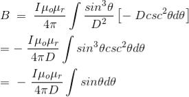
Finally, the expression of B comes as,
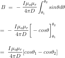
This angle θ depends upon the length of the wire and the position of the point P. Say for a certain limited length of the wire, angle θ as indicated in the figure above varies from θ1 to θ2. Hence, magnetic flux density at point P due to the total length of the conductor is,
Let’s imagine the wire is infinitely long, then θ will vary from 0 to π that is θ1 = 0 to θ2 = π. Putting these two values in the above final expression of Biot Savart law, we get,
This is nothing but the expression of Ampere’s Law.
|
Key Takeaways
- The Biot Savart Law is an equation describing the magnetic field generated by a constant electric current.
- It relates the magnetic field to the magnitude, direction, length, and proximity of the electric current.
- The Biot-Savart law can be stated as:

The static electric field E(x; y; z) such as the field of static charges obeys equations ∇. E =
The static magnetic field B(x; y; z) such as the field of steady currents obeys different equations
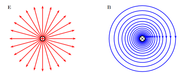
Figure 2: Electric and Magnetic Fields
Due to this difference, the magnetic field of long straight wire looks quite different from the electric field of a point charge or a linear charge. Later in these notes we will derive equations (3.2c) and (3.2d) from the Biot Savart Law. Let us explore some of their consequences. The zero-divergence equation (3.2c) is valid for any magnetic field, even if it is time-dependent rather than static. Physically, it means that there are no magnetic charges, otherwise we would have ∇.B Consequently, the magnetic field lines never begin or end anywhere in space; instead they form closed loops or run from in infinity to in infinity. The integral form of eq. (3.2c) follows by the Gauss theorem: the magnetic flux through any closed surface is zero
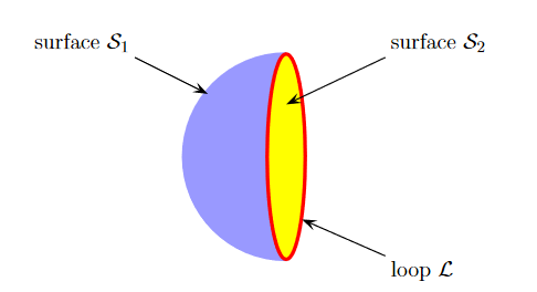
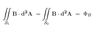
Consequently, any open surfaces S1,S2,……..spanning the same loop L have the same magnetic flux through them, for example
Figure 3: Open Surface
We shall this identity very useful for stating the Faraday's Law of magnetic induction. Now consider the curl equation
which is the differential form of the Ampere's Law. The integral form of the Ampere's Law obtains by the Stokes' theorem: For any closed loop L and any surface S spanning that loop,
………..(3.2e)
Where Inet [through L] is the net electric current flowing through the loop L. The integral form (3.2e) of the Ampere's Law is particularly convenient when the current flows through a wire or several wires; in this case all we need is to check which wire goes through the loop L and which does not, then add up the currents in the wires that do go through L and mind their directions. But it is also convenient for the volume currents flowing through thick conductors or for current sheets flowing on surfaces. As we know that the Ampere's Law applies only to the magnetic fields of steady currents. Otherwise, we need to use the more general Maxwell {Ampere Law, with an extra term for the time-dependent electric field. For simplicity we say that the original Ampere's Law is simply mathematically inconsistent unless the electric current has zero divergence,∇J= 0.Indeed, the left hand side of the curl equation ∇. ( So we cannot have ( ∇.J= 0. As to the integral form (3.2e) of the Ampere's Law, we need a divergence-less current density J to make sure that the net current through the loop L is the same for any surface S spanning the loop; otherwise we simply cannot de ne the net current through L
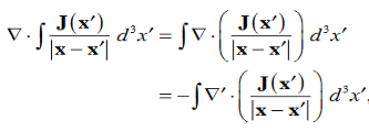
DERIVATION OF DIVERGENCE AND CURL OF MAGNETIC FIELD In general, when dealing with a current density J(x’) instead of a current I so (equation 1 of article 3.1) for the magnetic induction B(x) takes the form
Equation (1) can be expressed differently, since
but since
We get
If we set
Equation (5) is a mathematical statement on the inexistence of magnetic monopoles. Taking the curl of the B field, Using this identity
……….(5)
Solving this we get
This equation can be further simplified by using the divergence theorem
Since
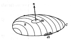
If we evaluate the integral on both sides of equation (7) over an open surface S of contour C (see Figure 4), we find
Figure 4: A magnetic induction is induced around a circuit C by a current density J through the open surface S bounded by C.
and using Stokes’ theorem
c where I is the current passing through the surface. Equations (8) and (9) are mathematical representations of Ampère’s Law.
|
Key Takeaways
|
Since we know from equation (3.2c) that the divergence of the magnetic induction is zero, it follows that the B field can be expressed as the curl of another vector field. Introducing the potential vector A(x), we can write B(x) = Referring to equation (4) of article 3.2, we find that the most general equation for A is
Where is some arbitrary scalar function. Inserting equation (2) into equation (3.2d) We get
But because of the freedom brought by the presence of
Just as
is the solution to the Poisson equation (
Equation (7) is valid in general, as we can set reduces to
Since
CALCULATING IT FOR A GIVEN MAGNETIC FIELD USING STOKES’ THEOREM The magnetic field B(r) determines the vector potential A(r) only up to a gradient of an arbitrary scalar field A’(x,y,z) = A(x,y,z) + have the same curl everywhere, so they correspond to the same magnetic field, B’(x,y,z) = The relations (9) between different vector potentials for the same magnetic field are called the gauge transforms. Despite ambiguity of the vector potential itself, some of its properties are gauge invariant i.e., the same for all potentials related by gauge transforms. For example, for any closed loop L, the integral.
is gauge invariant; indeed,
………..(12) Physically, the integral (11) in the magnetic flux through the loop L. Indeed, take any surface S spanning the loop L; by the Stokes' theorem,
………..(13) We may use eq. (13) to easily find the vector potential for a magnetic field which has some symmetries. For example, consider the uniform magnetic field B=B A(s, ϕ, z) = A(s) While the magnitude A(s) follows from eq. (13): Take a circle of radius s < R solenoid, then
While the magnetic flux through that circle is
Hence
In Cartesian coordinates, the vector potential becomes
Which makes it easy to verify
Eq. (18) gives the vector potential inside the long solenoid. Outside the solenoid, the magnetic field is negligible, but the flux through a circle of radius s > R solenoid is non-zero due to the flux inside the solenoid. Thus,
and hence
In vector notations
which agrees with the zero magnetic field outside the solenoid,
|
Key Takeaways
|
Magnetization, Bound Currents, and the H Field. In magnetic materials, atoms and molecules may have non-zero average magnetic moments ⟨m⟩. Such magnetic moments are usually induced by external magnetic fields, but in permanent magnets they can remain long after the external field is switched off. One way or the other, the atomic/molecular magnetic moments lead to macroscopic magnetization. M= Here we shall explore the macroscopic magnetic field B(x; y; z) due to such magnetization. Let's start with the vector potential A(x; y; z) due to a single magnetic dipole m,
By the superposition principle, the vector potential of a bunch of magnetic dipoles is a sum of potentials like (2)
Likewise, for a continuous distribution of dipoles with macroscopic magnetization M(x; y; z),we have
To simplify this expression, we note that
and then integrate by parts:
Applying these formulae to the integrand of eq. (4), we arrive at
…………(7)
Moreover, the second term on the RHS can be rewritten as a surface integral, for any vector field T(r) and any volume V with surface S,
…………(8) Where n(r) is a unit vector normal to the surface S at point r. In the present context, M(r′)/
…………(9) which has the form of a vector potential created by the volume current Jb(r′) =∇ and the surface current Kb(r′) =M(r′) indeed, in terms of these current, the potential (9) becomes
The currents (10) and (11) are called the bound currents, by analogy with the bound charges in a dielectric.
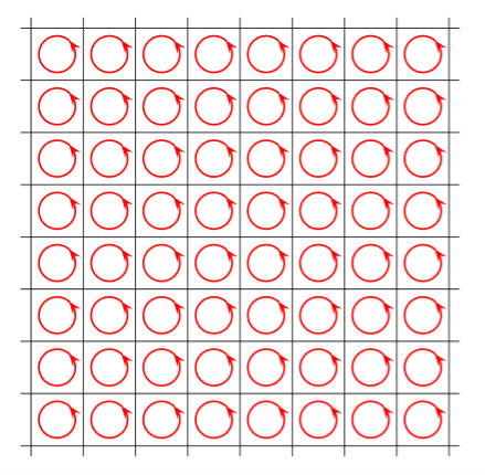
ORIGIN OF THE BOUND CURRENTS Physically, the bound currents on the surface of a magnetized material (and also in its volume for a non-uniform M) originate from the mis-cancellation of the microscopic currents inside the atoms which give rise to their magnetic moments. As a model of how this works, consider a large L m=a3M …………(1) The picture below shows a single slice of this cubic lattice along the (x; y) plane, or rather a small part of that slice:
Figure 5: Origin of the bound currents
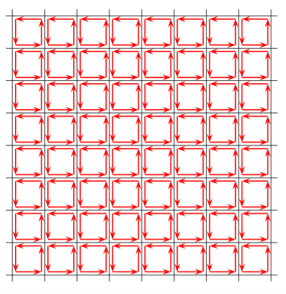
The red loops here stand for the current loops creating the atomic magnetic moments m. We do not know the radii or even the shapes of these loops or the currents which flow through them; we do not even know if the currents are line currents or volume currents. But for our purposes all such details do not matter, all we care is the net magnetic moment m of each atom. As far as the macroscopic magnetic field B(r) is concerned, we may replace each atom with an a I = flowing around the 4 vertical sides of the cube. Here is the picture of such a cubic model, or rather, of a small part of a single slice of the cubic lattice:
Figure 6: Origin of the bound currents
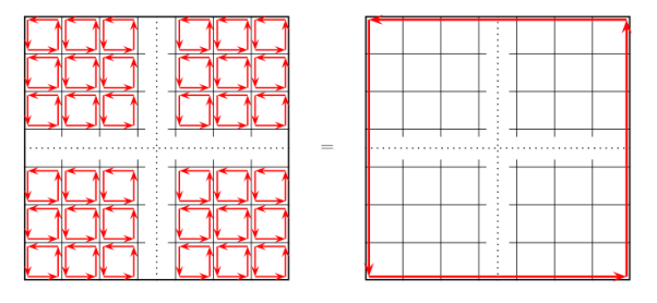
Inside each atom, the current flows counter clockwise. But when we look at the boundary between two neighbouring atoms, we immediately see that over that boundary, the currents of the two atoms flow in opposite directions. And since they have the same magnitude I=m/a2, they cancel each other. Thus, in the middle of the crystal all the atomic currents cancel each other and there is no net current. However, at the outer boundary of the crystal there is no cancellation.
Figure 7: Bound currents
Instead, there is un-cancelled current I=m/a2 flowing counter clockwise around the entire outer boundary of the crystal, or rather of single atomic layer of the crystal. The next layer on top of the layer shown on the above picture has a similar current, and so is every other layer, which makes for a surface current density. K = Over the 4 vertical sides of the whole magnetized cube. In vector notations, the surface current on each side of the cube is K = M where n is the unit vector normal to the side in question. The above toy model explains the physical origin of the surface bound current. It does not have a volume bound current since we assumed a uniform magnetization inside the magnetic material. To model a non-uniform magnetization we should give different atoms different magnetic moments m and hence different atomic currents. Consequently, at the boundary of two neighbouring atoms we would no longer have exact cancellation of their currents, and that would give rise to bound volume currents inside the bulk of the magnetized material. Assuming for simplicity that all atomic magnetic moments point in z directions but their magnitudes slowly depend on x and y coordinated of the atom, the net current on the boundary between two atoms neighbouring in x direction is
while on the boundary between two atoms neighbouring in y direction
Averaging these currents over the volume of the magnetized crystal, we get the volume bound current
…………(7) |
Key Takeaways
4. Jb(r′) =∇ 5. The bound currents on the surface of a magnetized material (and also in its volume for a non-uniform M) originate from the mis-cancellation of the microscopic currents inside the atoms which give rise to their magnetic moments. |
An object containing a magnetization distribution can be modelled by replacing the magnetization by bound volume and surface currents Jb and Kb. If we add in some extra free current Jf not due to the magnetization (for example, by plugging the object into the electric mains), then the total current at a point inside the object is J=Jb+Jf ………………(1) Since Jb=∇×M ………………(2) by definition, we can write Ampère’s law as
∇× The quantity in parentheses is given the symbol H:
H is called the auxiliary magnetic field or sometimes just the magnetic field, with B being called the magnetic flux density. This allows a variant form of Ampère’s law: ∇×H = Jf ………………(7)
Where If is the free current enclosed by the path of integration. One thing that is a bit worrying is that the bound surface current Kb seems to have vanished in this derivation but Jackson gets round the problem by saying that the surface integral from which Kb was defined as is zero by assuming that the magnetization M is well-behaved and localized, and we can take the surface at infinity where M=0. He then states later that in some idealized problems, it is convenient to assume that M is discontinuous at the boundary between two objects (for example, between a magnetized object and the surrounding air), and in that case, the surface current term must be added in. However, in any ’real’ physical situation, discontinuities never occur so the surface term doesn’t appear and the definition of H above is valid. In any case, we can use this definition of H to calculate B more easily in some idealized situations. For example, if we have an infinitely long cylinder of radius R with a fixed M=kr First, we use the bound current approach Jb=∇×M ………………(10) = k Kb=M(R)× =kR Note that the total bound current is zero, since the total volume current is
Both bound currents effectively produce solenoids, so the field outside the cylinder is zero. Inside, we have field due to the surface current, which is Bk = and we must add to that the field due to those parts of the cylinder with a radius greater than the radius r of interest. The total current outside radius r is
so the total field is Bk = Using H, we can take a loop of integration of radius r centred on the z axis. Since there is no free current, we get
and from the symmetry of the problem we can conclude that H=0 Alternatively, we can work from the curl equation which gives ∇×H=0. This on its own isn’t enough to conclude that H=0, but we can also calculate the divergence ∇·H= Since ∇·B=0 always, and by direct calculation we can show that ∇·M=0 in this case, we have both the curl and divergence of H as zero, so H must be zero. From that, we can conclude immediately from the definition of H that B=μ0M. |
Key Takeaways
|
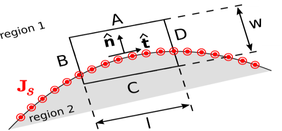
In homogeneous media, electromagnetic quantities vary smoothly and continuously. At a boundary between dissimilar media, however, it is possible for electromagnetic quantities to be discontinuous. Continuities and discontinuities in fields can be described mathematically by boundary conditions and used to constrain solutions for fields away from these boundaries. In this section, we derive boundary conditions on the magnetic field intensity H.
Figure 8: Determining the boundary condition on H at the smooth boundary between two material regions. To begin, consider a region consisting of only two media that meet at a smooth boundary as shown in above Figure. The desired boundary condition can be obtained directly from Ampere’s Circuital Law ∮C H⋅dl= Iencl ……….(1) where C is any closed path and Iencl is the current that flows through the surface bounded by that path in the direction specified by the “right-hand rule” of Stokes’ theorem. Let C take the form of a rectangle centered on a point on the boundary as shown in Figure, perpendicular to the direction of current flow at that location. Let the sides A, B, C, and D be perpendicular and parallel to the boundary. Let the length of the parallel sides be l, and let the length of the perpendicular sides be w. Now we apply Ampere’s Circuital Law, We must integrate in a counter-clockwise direction in order to be consistent with the indicated reference direction for Js Thus: ∮H⋅dl=∫A H⋅dl+∫B H⋅dl+∫C H⋅dl+∫D H⋅dl=Iencl Now we let w and l become vanishingly small while maintaining the ratio l/w and keeping C centered on the boundary. In this process, the contributions from the B and D segments become equal in magnitude but opposite in sign; i.e., ∫B H⋅dl +∫D H⋅dl →0 ………(2) This leaves ∫A H⋅dl+∫C H⋅dl=Iencl Let us define the unit vector H1⋅(− Where H1 and H2 are the fields evaluated on the two sides of the boundary, and Δl→0 is the length of sides A and C. As always, Iencl (units of A) may be interpreted as the flux of the current density Js (units of A/m) flowing past a line on the surface having length Δl (units of m) perpendicular to Iencl →Js ⋅(Δl Before proceeding, note this is true regardless of the particular direction we selected for H1⋅(− Eliminating the common factor of Δl and arranging terms on the left: (H2−H1)⋅ The right side may be transformed using a vector identity (A⋅(B×C)=B⋅(C×A)=C⋅(A×B) to obtain: (H2−H1)⋅ Equation (7) is the boundary condition we seek. We have found that the component of (H2−H1) (the difference between the magnetic field intensities at the boundary) in any direction tangent to the boundary is equal to the component of the current density flowing in the perpendicular direction A discontinuity in the tangential component of the magnetic field intensity at the boundary must be supported by surface current flowing in a direction perpendicular to this component of the field. An important consequence is that If there is no surface current, then the tangential component of the magnetic field intensity is continuous across the boundary. It is possible to obtain a mathematical form of the boundary condition that is more concise and often more useful than Equation (7). This form may be obtained as follows. First, we note that the dot product with respect to For example so Equation (7) may be equivalently written as follows:
Applying a vector identity (A×(B×C)=B(A⋅C)−C(A⋅B) to the right side of Equation (8) we obtain:
Therefore:
The minus sign on the right can be eliminated by swapping H2 and H1 on the left, yielding
This is the form in which the boundary condition is most commonly expressed. It is worth noting what this means for the magnetic field intensity B. Since B=μH In the absence of surface current, the tangential component of B across the boundary between two material regions is discontinuous if the permeabilities are unequal. |
Key Takeaways
|
The magnetic effects in magnetic materials are due to atomic magnetic dipoles in the materials. These dipoles result from effective current loops of electrons in atomic orbits, from effects of electron spin & from the magnetic moments of atomic nuclei.
The electric currents in an atom are caused by orbital and spin motions of electrons and those of its nucleus. Since all these motions of charged particles form closed electric currents, they are equivalent to “magnetic dipoles”. When such dipoles are subjected to an external electric field, they experience a torque which tends to align their magnetic moments in the direction of the externally applied field.
Some Important Definitions
Magnetic dipole
Each tiny dimension of a magnetic material (or) atoms in magnetic materials is called magnetic dipole. This magnetic dipole produces magnetic moment depending on the alignment with respect to the applied magnetic field.
Magnetic flux (Ф)
It is defined as the amount of magnetic lines of forces passing perpendicularly through unit area of a given material. It is denoted by ‘Ф’
Ф=AB
Where A= Area of cross section of the material in m2
B = magnetic Induction in Wb/ m2
Units: Weber (Wb)
Intensity of Magnetization (M)
When a material is magnetized, it develops a net magnetic moment. The magnetic moment per unit volume is called Intensity of magnetization.
Magnetization (M) =
|
Units: Amp/m
Magnetic Induction (B)
Magnetic induction at a point is defined as the force experienced by a unit North Pole Placed at that point. It is denoted by ‘B’ i.e.
B = |
Unit is weber / m2
Magnetizing field strength (H)
When a medium is exposed to a magnetic field of intensity ‘H’, it causes an induction ‘B’ in the medium.i.e. B H B = μH Where μ = absolute permeability of the medium. If the medium is air or vacuum B=μ0H μ0=permeability of free space i.e. air or vacuum μ0=4𝜋×10-7 H/m Units for H: Amp /m |
Permeability (μ)
It indicates with which the material allows magnetic lines of force to pass through it. Or It is the ability of the medium to pass magnetic lines of forces through it. There are three Permeabilities i.e. μ1,μ0, μr μ = μ0μr Where μ = Absolute permeability of the medium μ0 = Permeability of free space i.e. air or vacuum μr = Relative permeability of the medium |
Magnetic moment
Magnetic moment μm = (current) × (area of circulating orbit) μm = (I) × (𝜋r2) Units: Amp-m2 |
When the magnetic dipoles (atoms consisting of charged particles like protons & neutrons) undergo orbital motion (or) spin motion produces a magnetic moment. Since motion of charged particles is considered as closed electric current loops which in turn produces a magnetic moment.
Magnetic susceptibility (χ)
If H is the applied magnetizing field intensity and M is the amount of magnetization of the material,
Then
χ = χ = 0 in vacuum χ = +ve for paramagnetic and Ferro magnetic materials χ = -ve for diamagnetic materials Units: It has no units. |
CLASSIFICATION OF MAGNETIC MATERIALS
Magnetic materials are classified as follows:
- Diamagnetic
- Paramagnetic
- Ferro magnetic
- Anti-Ferro magnetic
- Ferric magnetic or ferrites
DIAMAGNETIC
The orbital motion of electrons around the nucleus produces a magnetic field perpendicular to the plane of the orbit. Thus, each electron orbit has finite orbital magnetic dipole moment. Since the orbital planes are oriented in random manner, the vector sum of magnetic moments is zero and there is no resultant magnetic moment for each atom.
In the presence of an external magnetic field, some electrons are speeded up and some are slowed down. The electrons whose moments were anti-parallel are speeded up according to Lenz’s law and this produces an induced magnetic moment in a direction opposite to the field. The induced moment disappears as soon as the external field is removed.
When placed in a non-uniform magnetic field, the interaction between induced magnetic moment and the external field creates a force which tends to move the material from stronger part to weaker part of the external field. It means that diamagnetic material is repelled by the field.
This action is called diamagnetic action and such materials are known as diamagnetic materials. Examples: Bismuth, Copper and Water etc.
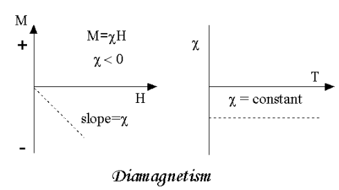
Diamagnetism is a fundamental property of all matter, although it is usually very weak. It is due to the non-cooperative behaviour of orbiting electrons when exposed to an applied magnetic field. Diamagnetic substances are composed of atoms which have no net magnetic moments (ie., all the orbital shells are filled and there are no unpaired electrons). However, when exposed to a field, a negative magnetization is produced and thus the susceptibility is negative. If we plot M vs H, we see
|
Figure 9: Diamagnetic
Note that when the field is zero the magnetization is zero. The other characteristic behaviour of diamagnetic materials is that the susceptibility is temperature independent. Some well-known diamagnetic substances, in units of 10-8 m3/kg, include:
Quartz (SiO2) -0.62
Calcite (CaCO3) -0.48
Water -0.90
The properties of diamagnetic materials are
- Magnetic susceptibility is negative.
- Relative permeability is slightly less than unity.
- The magnetic field lines are repelled or expelled by diamagnetic materials when placed in a magnetic field.
- Susceptibility is nearly temperature independent.
- Examples: Cu, Au, Zn, H20, Bi etc. organic materials
PARAMAGNETIC MATERIALS
In some magnetic materials, each atom or molecule has net magnetic dipole moment which is the vector sum of orbital and spin magnetic moments of electrons. Due to the random orientation of these magnetic moments, the net magnetic moment of the materials is zero.
In the presence of an external magnetic field, the torque acting on the atomic dipoles will align them in the field direction. As a result, there is net magnetic dipole moment induced in the direction of the applied field. The induced dipole moment is present as long as the external field exists.
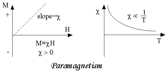
As we come to know this class of materials, some of the atoms or ions in the material have a net magnetic moment due to unpaired electrons in partially filled orbitals. One of the most important atoms with unpaired electrons is iron. However, the individual magnetic moments do not interact magnetically, and like diamagnetism, the magnetization is zero when the field is removed. In the presence of a field, there is now a partial alignment of the atomic magnetic moments in the direction of the field, resulting in a net positive magnetization and positive susceptibility.
|
Figure 10: Paramagnetism
In addition, the efficiency of the field in aligning the moments is opposed by the randomizing effects of temperature. This results in a temperature dependent susceptibility, known as the Curie Law.
At normal temperatures and in moderate fields, the paramagnetic susceptibility is small (but larger than the diamagnetic contribution). Unless the temperature is very low (<<100 K) or the field is very high paramagnetic susceptibility is independent of the applied field. Under these conditions, paramagnetic susceptibility is proportional to the total iron content. Many iron bearing minerals are paramagnetic at room temperature. Some examples, in units of 10-8 m3/kg, include:
Montmorillonite (clay) 13
Nontronite (Fe-rich clay) 65
Biotite (silicate) 79
Siderite (carbonate) 100
Pyrite (sulphide) 30
The paramagnetism of the matrix minerals in natural samples can be significant if the concentration of magnetite is very small. In this case, a paramagnetic correction may be needed.
The properties of paramagnetic materials are:
- Magnetic susceptibility is positive and small.
- Relative permeability is greater than unity.
- The magnetic field lines are attracted into the paramagnetic materials when placed in a magnetic field.
- Susceptibility is inversely proportional to temperature.
An atom or a molecule in a ferromagnetic material possesses net magnetic dipole moment as in a paramagnetic material. A ferromagnetic material is made up of smaller regions, called ferromagnetic domain. Within each domain, the magnetic moments are spontaneously aligned in a direction. This alignment is caused by strong interaction arising from electron spin which depends on the inter-atomic distance. Each domain has net magnetisation in a direction. However the direction of magnetisation varies from domain to domain and thus net magnetisation of the specimen is zero.
In the presence of external magnetic field, two processes take place
1. the domains having magnetic moments parallel to the field grow in size
2. the other domains (not parallel to field) are rotated so that they are aligned with the field.
As a result of these mechanisms, there is a strong net magnetisation of the material in the direction of the applied field
When placed in a non-uniform magnetic field, the ferromagnetic materials will have a strong tendency to move from weaker to stronger part of the field. Materials which exhibit strong magnetism in the direction of applied field are called ferromagnetic materials.
When you think of magnetic materials, you probably think of iron, nickel or magnetite. Unlike paramagnetic materials, the atomic moments in these materials exhibit very strong interactions. These interactions are produced by electronic exchange forces and result in a parallel or antiparallel alignment of atomic moments. Exchange forces are very large, equivalent to a field on the order of 1000 Tesla, or approximately a 100 million times the strength of the earth's field.
The exchange force is a quantum mechanical phenomenon due to the relative orientation of the spins of two electrons.
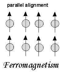
Ferromagnetic materials exhibit parallel alignment of moments resulting in large net magnetization even in the absence of a magnetic field.
|
The elements Fe, Ni, and Co and many of their alloys are typical ferromagnetic materials.
Two distinct characteristics of ferromagnetic materials are their
(1) Spontaneous magnetization and
(2) Magnetic ordering temperature
Spontaneous Magnetization
The spontaneous magnetization is the net magnetization that exists inside a uniformly magnetized microscopic volume in the absence of a field. The magnitude of this magnetization, at 0 K, is dependent on the spin magnetic moments of electrons.
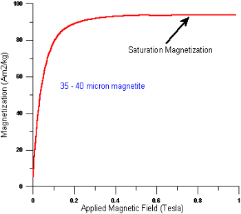
A related term is the saturation magnetization which we can measure in the laboratory. The saturation magnetization is the maximum induced magnetic moment that can be obtained in a magnetic field (Hsat); beyond this field no further increase in magnetization occurs.
The difference between spontaneous
|
magnetization and the saturation magnetization has to do with magnetic
domains (more about domains later). Saturation magnetization is an intrinsic property, independent of particle size but dependent on temperature.
There is a big difference between paramagnetic and ferromagnetic susceptibility. As compared to paramagnetic materials, the magnetization in ferromagnetic materials is saturated in moderate magnetic fields and at high (room-temperature) temperatures:
| Hsat Tesla | T range (K) | χ 10-8m3/kg |
paramagnets | >10 | <<100 | ~50 |
ferromagnets | ~1 | ~300 | 1000-10000 |
The properties of ferromagnetic materials are:
- Magnetic susceptibility is positive and large.
- Relative permeability is large.
- The magnetic field lines are strongly attracted into the ferromagnetic materials when placed in a magnetic field.
- Susceptibility is inversely proportional to temperature.
ANTIFERROMAGNETISM
In the periodic table the only element exhibiting antiferromagnetism at room temperature is chromium. Antiferromagnetic materials are very similar to ferromagnetic materials but the exchange interaction between neighbouring atoms leads to the anti-parallel alignment of the atomic magnetic moments. Therefore, the magnetic field cancels out and the material appears to behave in the same way as a paramagnetic material. Like ferromagnetic materials these materials become paramagnetic above a transition temperature, known as the Neel temperature, TN. (Cr: TN=37ºC).
The properties of antiferromagnetic materials are:
- They have permanent magnetic dipoles
- They do not possess permanent magnetic dipole moment. Since in the absence of field they have no spontaneous magnetization due to anti parallel spin
- The relative permeability μr>1
- Susceptibility χ is small but negative
- 𝜒depends on temperature
FERRIMAGNETISM
Ferrimagnetism is only observed in compounds, which have more complex crystal structures than pure elements. Within these materials the exchange interactions lead to parallel alignment of atoms in some of the crystal sites and anti-parallel alignment of others. The material breaks down into magnetic domains, just like a ferromagnetic material and the magnetic behaviour is also very similar, although ferrimagnetic materials usually have lower saturation magnetisations. For example, in Barium ferrite (BaO.6Fe2O3) the unit cell contains 64 ions of which the barium and oxygen ions have no magnetic moment, 16 Fe3+ ions have moments aligned parallel and 8 Fe3+ aligned anti-parallel giving a net magnetisation parallel to the applied field, but with a relatively low magnitude as only ⅛ of the ions contribute to the magnetisation of the material.
The properties of ferrimagnetic materials are:
- They have permanent magnetic dipoles.
- They possess permanent magnetic diploe moment. Also in the absence of field they have spontaneous magnetization. Since spin is anti-parallel but of different magnitudes
- The relative permeability μr>>1
- Susceptibility is large and positive
- 𝜒 depend on temperature
Key Takeaways
- The magnetic effects in magnetic materials are due to atomic magnetic dipoles in the materials.
- The electric currents in an atom are caused by orbital and spin motions of electrons and those of its nucleus.
- Magnetic materials are classified as Diamagnetic, Paramagnetic, Ferromagnetic, Anti-Ferro magnetic.
- Diamagnetic material is repelled by the field and having negative Magnetic susceptibility.
- In paramagnetic materials the magnetic field lines are attracted to the paramagnetic materials when placed in a magnetic field. Magnetic susceptibility is positive and small.
- Materials that exhibit strong magnetism in the direction of the applied field are called ferromagnetic materials. Magnetic susceptibility is positive and large.
- Antiferromagnetic materials are very similar to ferromagnetic materials but the exchange interaction between neighbouring atoms leads to the anti-parallel alignment of the atomic magnetic moments. Susceptibility χ is small but negative
When a material is placed within a magnetic field, the magnetic forces of the material's electrons will be affected. This effect is known as Faraday's Law of Magnetic Induction. However, materials can react quite differently to the presence of an external magnetic field. This reaction is dependent on a number of factors, such as the atomic and molecular structure of the material, and the net magnetic field associated with the atoms. The magnetic moments associated with atoms have three origins. These are the electron motion, the change in motion caused by an external magnetic field, and the spin of the electrons.
In most atoms, electrons occur in pairs. Electrons in a pair spin in opposite directions. So, when electrons are paired together, their opposite spins cause their magnetic fields to cancel each other. Therefore, no net magnetic field exists. Alternately, materials with some unpaired electrons will have a net magnetic field and will react more to an external field. Most materials can be classified as diamagnetic, paramagnetic or ferromagnetic.
INTERACTION OF MAGNETIC FIELDS AND MATERIALS
At this point, we don't even have a really good understanding of a bar magnet works, an unsatisfying state of affairs, given that this is the way in which we normally encounter magnetism in the real world.
One reason we have avoided covering this subject is that it is not really possible to discuss it properly within getting into a detailed discussion of the quantum mechanical description of matter. The way in which matter responds to magnetic fields is totally determined by the quantum mechanical nature of their molecular structure, particularly their electrons.
None the less, we can make significant headway in understanding the interaction of magnetic fields and materials by combining what we have learned so far with a somewhat approximate, qualitative description of how materials respond to magnetic fields. The main concepts we will need are summarized in the following two subsections.
ELECTRON ORBITALS
The electrons in a molecule exist in orbits. Very roughly, we can picture an orbital a simple loop of current: A loop of current like this of course tends to generate its own magnetic field. In most materials, there are an enormous number of orbits like this, randomly oriented so that they produce no net field. Suppose an external magnetic field is applied to some substance that contains many orbitals like this.
|
Figure 13: Electron Orbital
The net tendency can be understood in terms of Lenz's law: the orbits rearrange "themselves in order to oppose the change in magnetic flux. This tendency for Lenz's law to work on the microscopic scale ends up oposing the magnetic field from the material.
INTRINSIC MAGNETIC MOMENT OF THE ELECTRON
One other quantum mechanical property of electrons plays an extremely important role in this discussion: electrons have a built-in, intrinsic magnetic moment. Roughly speaking,
This means that each electron all on its own acts as a source of magnetic field, producing a dipole-type field very similar to that of current loop. Because this field is associated with the electron itself, it does not exhibit the Lenz's law type behaviour of the field that we see from the orbits.
Instead, the most important behaviour in this context is the fact that a magnetic moment  placed in an external field
  feels a torque.
|
In this case, the action of this torque tends to line up the electrons' magnetic moments with the external field. In this case, you find that the magnetic field is augmented within the material.
To summarize the above discussion, the quantum mechanical nature of electrons in molecules leads to two behaviours
Lenz's law on the scale of electron orbitals opposes magnetic fields from entering a material.
Magnetic torque acting on the individual electrons augments magnetic fields in a material.
These two behaviours are in complete opposition to one another. However, both occur, and both are important. A natural question to ask is: Which of these two behaviours is more important?
The answer to this question varies from material to material, depending upon its detailed electronic orbital structure.
The first property- Lenz's law on the orbital scale| plays some role in all materials. In many cases, this is the end of the story. Such materials are called diamagnetic. A diamagnetic material is one whose magnetization (to be defined precisely in a moment) opposes an external magnetic field. Even though almost all materials are diamagnetic, the effect is so puny that it is typically very difficult to see. A consequence of this is that a diamagnetic substance will be expelled from a magnetic field.
For some materials, the second property alignment of electron magnetic moments wins out. Such materials typically have several electron orbits that contain unpaired electrons; the orbit thus has a net magnetic moment. (In most diamagnetic materials, the orbits are filled with paired electrons, so that the orbit has no net moment) Such materials are called paramagnetic. A paramagnetic material has a magnetization that augments an external field. Paramagnetic substances are pulled into a magnetic field. In the vast majority of cases, paramagnetic effects are also so puny that they can barely be seen.
One particular class of materials acts essentially as paramagnetic materials do. However, they respond so strongly that they truly belong in a class of their own. These are the ferromagnetic materials.
Key Takeaways
- The magnetic moments associated with atoms have three origins. These are the electron motion, the change in motion caused by an external magnetic field, and the spin of the electrons.
- In most atoms, electrons occur in pairs. Electrons in a pair spin in opposite directions. So, when electrons are paired together, their opposite spins cause their magnetic fields to cancel each other. Therefore, no net magnetic field exists.
- Alternately, materials with some unpaired electrons will have a net magnetic field and will react more to an external field.
- This tendency for Lenz's law to work on the microscopic scale ends up opposing the magnetic field from the material.
- Electrons have a built-in, intrinsic magnetic moment.
References
- David Griffiths, ‘Introduction to Electrodynamics’.
- S.P. Puri, ‘Classical Electrodynamics’, Tata McGraw Hill
- Gupta & Gaur, ‘Engineering Physics’, Dhanpat Rai.
- Malik and Singh, ‘Engineering Physics’, Tata McGraw Hill.
- Naidu, ‘Engineering Physics’, Pearson.


