UNIT-3
FARADAY’S LAWS AND MAXWELL’S EQUATIONS
Faraday’s law of electromagnetic induction (referred to as Faraday’s law) is a basic law of electromagnetism predicting how a magnetic field will interact with an electric circuit to produce an electromotive force (EMF). This phenomenon is known as electromagnetic induction.
Faraday’s law states that a current will be induced in a conductor which is exposed to a changing magnetic field. Lenz’s law of electromagnetic induction states that the direction of this induced current will be such that the magnetic field created by the induced current opposes the initial changing magnetic field which produced it. The direction of this current flow can be determined using Fleming’s right-hand rule.
Let us understand Faraday’s law by faraday‘s experiment.
FARADAY’S EXPERIMENT
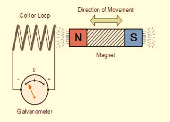
In this experiment, Faraday takes a magnet and a coil and connects a galvanometer across the coil. At starting, the magnet is at rest, so there is no deflection in the galvanometer i.e. the needle of the galvanometer is at the center or zero position. When the magnet is moved towards the coil, the needle of the galvanometer deflects in one direction.
|
Figure 1: Faraday’s law of electromagnetic induction
When the magnet is held stationary at that position, the needle of galvanometer returns to zero position. Now when the magnet moves away from the coil, there is some deflection in the needle but opposite direction, and again when the magnet becomes stationary, at that point respect to the coil, the needle of the galvanometer returns to the zero position.
Similarly, if the magnet is held stationary and the coil moves away, and towards the magnet, the galvanometer similarly shows deflection. It is also seen that the faster the change in the magnetic field, the greater will be the induced EMF or voltage in the coil.
Let us take a look at the following table. This table is showing the observation of faraday’s experiment.
Position of magnet | Deflection in galvanometer |
Magnet at rest | No deflection in the galvanometer |
Magnet moves towards the coil | Deflection in galvanometer in one direction |
Magnet is held stationary at same position (near the coil) | No deflection in the galvanometer |
Magnet moves away from the coil | Deflection in galvanometer but in the opposite direction |
Magnet is held stationary at the same position (away from the coil) | No deflection in the galvanometer |
CONCLUSION
From this experiment, Faraday concluded that whenever there is relative motion between a conductor and a magnetic field, the flux linkage with a coil changes and this change in flux induces a voltage across a coil.
Michael Faraday formulated two laws on the basis of the above experiments. These laws are called Faraday’s laws of electromagnetic induction.
FARADAY’S FIRST LAW
Any change in the magnetic field of a coil of wire will cause an emf to be induced in the coil. This emf induced is called induced emf and if the conductor circuit is closed, the current will also circulate through the circuit and this current is called induced current.
Method to change the magnetic field:
- By moving a magnet towards or away from the coil
- By moving the coil into or out of the magnetic field
- By changing the area of a coil placed in the magnetic field
- By rotating the coil relative to the magnet
FARADAY’S SECOND LAW
It states that the magnitude of emf induced in the coil is equal to the rate of change of flux that linkages with the coil. The flux linkage of the coil is the product of the number of turns in the coil and flux associated with the coil.
According to Faraday’s law of electromagnetic induction, the rate of change of flux linkage is equal to induced emf.
Considering Lenz’s Law Where:
|
FACTORS ON WHICH INDUCED EMF DEPEND
- By increasing the number of turns in the coil i.e. N, from the formulae derived above it is easily seen that if the number of turns in a coil is increased, the induced emf also gets increased.
- By increasing magnetic field strength i.e. B surrounding the coil- Mathematically, if magnetic field increases, flux increases and if flux increases emf induced will also get increased. Theoretically, if the coil is passed through a stronger magnetic field, there will be more lines of force for the coil to cut and hence there will be more emf induced.
- By increasing the speed of the relative motion between the coil and the magnet – If the relative speed between the coil and magnet is increased from its previous value, the coil will cut the lines of flux at a faster rate, so more induced emf would be produced.
APPLICATIONS OF FARADAY’S LAW
Faraday law is one of the most basic and important laws of electromagnetism. This law finds its application in most of the electrical machines, industries, and the medical field, etc.
- Power transformers function based on Faraday’s law
- The basic working principle of the electrical generator is Faraday’s law of mutual induction.
- The Induction cooker is the fastest way of cooking. It also works on the principle of mutual induction. When current flows through the coil of copper wire placed below a cooking container, it produces a changing magnetic field. This alternating or changing magnetic field induces an emf and hence the current in the conductive container, and we know that the flow of current always produces heat in it.
- Electromagnetic Flow Meter is used to measure the velocity of certain fluids. When a magnetic field is applied to an electrically insulated pipe in which conducting fluids are flowing, then according to Faraday’s law, an electromotive force is induced in it. This induced emf is proportional to the velocity of fluid flowing.
- From bases of Electromagnetic theory, Faraday’s idea lines of force is used in well-known Maxwell’s equations. According to Faraday’s law, change in magnetic field gives rise to change in electric field and the converse of this is used in Maxwell’s equations.
- It is also used in musical instruments like an electric guitar, electric violin, etc.
Key Takeaways
- Any change in the magnetic field of a coil of wire will cause an emf to be induced in the coil. This emf induced is called induced emf .
- If the conductor circuit is closed, the current will also circulate through the circuit and this current is called induced current.
- Magnetic field can be change by moving a magnet towards or away from the coil, by moving the coil into or out of the magnetic field, by changing the area of a coil placed in the magnetic field, by rotating the coil relative to the magnet.
- Faraday’s law states that the magnitude of emf induced in the coil is equal to the rate of change of flux that linkages with the coil.
- The flux linkage of the coil is the product of the number of turns in the coil and flux associated with the coil.
Time-varying magnetic field will always produce an electric field. According to the faraday’s law “Whenever there are n-turns of conducting coil in a closed path which is placed in a time-varying magnetic field, an alternating electromotive force gets induced in each and every coil.” This is given by Lenz’s law. Which states that an induced electromotive force always opposes the time-varying magnetic flux.
When two coils with N number of turns; A primary coil and Secondary coil. The primary coil is connected to an alternating current source and the secondary coil is connected in a closed loop and is placed at a small distance from the primary coil. When an AC current passes through the primary coil, an alternating electromotive force gets induced in the secondary coil.
Mathematically it is expressed as –
Alternating emf, emfalt=−Ndϕdt ——–(1) Where, N is the number of turns in a coil 𝜙 is the scalar magnetic flux. The negative sign indicates that the induced emf always opposes the time-varying magnetic flux. Let N=1, ⇒ emfalt = − Here, the scalar magnetic flux can be replaced by – ϕ=∬B⃗ .ds⃗ ——–(3) Substitute equation (3) in (2) emfalt= − Which is an partial differential equation given by- emfalt = ∬− The alternating electromotive force induced in a coil is basically a closed path ⇒emfalt = ∮E⃗ .dl⃗ ——-(5) Substituting equation (5) in (4) we get- ⇒ ∮E⃗ dl⃗ = ∬− The closed line integral can be converted into surface integral using Stoke’s theorem. Which states that “Closed line integral of any vector field is always equal to the surface integral of the curl of the same vector field” ⇒∮E⃗ dl⃗ =∬( Substituting equation (7) in (6) we get- ⇒=∬( The surface integral can be cancelled on both sides. Thus, we arrive at
Hence, we can conclude that the time-varying magnetic field will always produce an electric field. This is the differential form of faraday’s law. It is also known as Maxwell-Faraday Equation. For the static magnetic field, which states that Static electric field vector is an irrotational vector. Static field implies the time-varying magnetic field is zero, ⇒ Hence it is an irrotational vector.
CALCULATING ELECTRIC FIELD DUE TO CHANGING MAGNETIC FIELDS IN QUASI-STATIC APPROXIMATION Faraday’s law in differential form is ∇×E = − There is a similarity to Ampère’s law, which says ∇×B = μ0 J ………… (2) Considering only electric fields generated from changing magnetic fields (and not those generated by free charges), we then have∇·E=0, since there is no free charge. For magnetic fields, ∇·B=0 always. Once we specify both the curl and divergence of a vector field, the field is deter-mined uniquely (up to a constant), so Faraday’s law is formally equivalent to Ampère’s law, except that curl is determined by − In particular, we can use the right hand rule to determine the direction of E if we know − In differential form, this doesn’t pose a problem, since both sides of the equation refer to a single point(x,y,z). However, in its original integral form:
The t variable is assumed to be the same at all points in the integrals. If we choose some enormous loop for the integral on the left, then any change in B, even one in some small, remote corner of the area enclosed by the loop, is implicitly assumed to affect E instantaneously around the entire loop. This is a problem inherent in all non-relativistic physics. In Newton’s gravitational theory, for example, no provision is made for any travel time from one mass to the other; if the sun were to suddenly lose half its mass, say, the effect would be felt at the Earth immediately. In reality, of course, nothing can travel faster than the speed of light, so changes in one part of a system will not be felt at other parts until some signal informing these remote parts of the change has reached them. In the case of electromagnetism, the signal speed happens to be exactly that of light, so when we apply Faraday’s law in integral form, we really need to take this into account. In practice, when we’re dealing with finite electrical circuits or situations within an Earth-bound laboratory, the distances are usually so short that we can make the approximation that the travel time is zero. This is known as the quasistatic approximation. As a simple example, suppose we have an infinite solenoid with n turns per unit length and of radius a, carrying a time-dependent current I(t). The fact that the solenoid is infinite means that the quasistatic approximation could well break down for large distances, but we’ll do the calculation anyway and see what we get. Inside the solenoid, the field is B=nμ0I(t) so − Note: Using the analogy between Ampère’s and Faraday’s laws, since the direction of −
E=− Outside the solenoid, B is always zero, so there is no contribution to E here. A circular integration path at a distance r > a still contains the flux inside the solenoid, so
E=−
|
Key Takeaways
|
Current Density
The amount of electric current traveling per unit cross-section area is called as current density and expressed in amperes per square meter.
Current density is a vector quantity having both a direction and a scalar magnitude. The electric current flowing through a solid having units of charge per unit time is calculated towards the direction perpendicular to the flow of direction. It is all about the amount of current flowing across the given region.
In case of a steady current is flowing through a conductor, same current flows through all the cross-sections of the conductor, even though the cross-sections may differ in area. Electric current is a macroscopic entity.
We here discuss electric current passing through a conductor and not about electric current at a point.
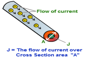
Current density J, at any point inside a conductor, is a vector quantity whose magnitude is equal to the current per unit area through an infinitesimal area at that point, the area being held perpendicular to the direction of flow of charge and its direction is along the direction of flow of positive charge.
|
Figure 2: Current density
More the current in a conductor, the higher will be the current density. However, the current density alters in different parts of an electrical conductor and the effect takes place with alternating currents at higher frequencies.
Electric current always creates a magnetic field. Stronger the current, more intense is the magnetic field. Varying AC or DC creates an electromagnetic field and this is the principle based on which signal propagation takes place.
Current Density Formula
The formula for Current Density is given as, J = I / A Where, I = current flowing through the conductor in Amperes A = cross-sectional area in m2. Current density is expressed in A/m2. In case of non-uniform flow, current I through any cross-section is
Here the integral denotes the surface integral over the entire cross-section.
|
Equation of continuity
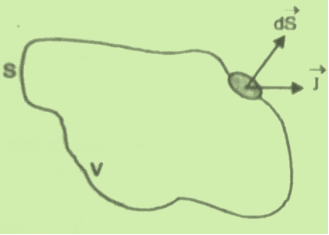
Consider a closed surface S enclosing a Volume V through which currents are flowing. Let I be the current passing through the surface at any time t. Consider a small area
Figure 3: Current density through surface S
dI = the total current flowing out through the closed surface S at time t is I = Suppose is ρ the Volume Charge density of charges inside the surface S. Then the total charge inside the Volume V is q = Since the current is flowing outward is it mean that charge within the enclosed surface is decreasing with time. The time rate of decrease of charge is
The negative sign shows that the charge inside the surface S is decreasing with time. The above equation can be written as
Since the charge is conserved, the current flowing outward through the closed surface must be equal to the rate of decrease of charge. Thus I = Using equation (2) and (5), it becomes
According to divergence theorem
Using this result in equation (6) we obtain
This equation holds good for arbitrary volumes. Therefore the integrands must be equal. Hence
This equation is called equation of continuity. It is the mathematical statement of law of conservation of charge. |
Special case
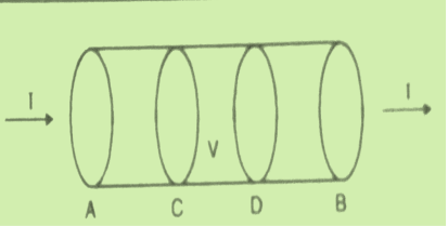
Consider a conductor AB through which a steady current I is flowing. The current I is said to be steady if charge is flowing per unit time through any two any sections C and D is the same. This means that the total amount of charge entering the volume V through C is equal to the charge leaving the volume V through D. Thus there is no change in the volume charge density in the volume V with time i.e.
Figure 4: Current through conductor AB
We may define steady current as that current in which the charge density is independent of time. Using equation (7) we obtain
This is known as the equation of continuity for steady currents.
|
Key Takeaways
|
Statement of Ampere’s circuital law (without modification). It states that the line integral of the magnetic field H around any closed path or circuit is equal to the current enclosed by the path. That is ∫ H. dL=I Let the current is distributed through the surface with a current density J Then I= This implies that Apply Stoke’s theorem to L.H.S. of equation (1) to change line integral to surface integral, That is Substituting above equation in equation (9), we get
As two surface integrals are equal only if their integrands are equal Thus, ∇ x H=J (2) This is the differential form of Ampere’s circuital Law (without modification) for steady currents. Take divergence of equation (2) ∇.(∇xH)= ∇.J As divergene of the curl of a vector is always zero ,therefore ∇.( ∇xH)=0 It means ∇.J=0 Now, this is equation of continuity for steady current but not for time varying fields, as equation of continuity for time varying fields is ∇ .J = – If we do some simple mathematical tricks to Maxwell's Equations, we can derive some new equations. Here we'll look at the continuity equation, which can be derived from Gauss' Law and Ampere's Law. We will start with a vector identity which states that the divergence of the curl of any vector field is always zero: ∇.( ∇xH)=0 …………(1) If we apply the divergence to both sides of Ampere's Law, then we obtain: ∇.( If we apply Gauss' Law to rewrite the divergence of the Electric Flux Density (D), we have derived the continuity equation ∇.J = – The left side of the equation is the divergence of the Electric Current Density (J). This is a measure of whether current is flowing into a volume (i.e. the divergence of J is positive if more current leaves the volume than enters).
|
Recall that current is the flow of electric charge. So if the divergence of J is positive, then more charge is exiting than entering the specified volume. If charge is exiting, then the amount of charge within the volume must be decreasing. This is exactly what the right side is a measure of how much electric charge is accumulating or leaving in a volume. Hence, the continuity equation is about continuity - if there is a net electric current is flowing out of a region, and then the charge in that region must be decreasing. If there is more electric current flowing into a given volume than exiting, than the amount of electric charge must be increasing.
Key Takeaways
|
J.C. Maxwell showed that for logical consistency, a changing electric field must also produce a magnetic field. Further, since magnetic fields have always been associated with currents, Maxwell postulated that this current was proportional to the rate of change of the electric field and called it displacement current.
How a changing electric field produces a magnetic field?
To determine this, let’s look at the process of charging a capacitor. Further, we will apply Ampere’s circuital law to find a magnetic point outside the capacitor.
|
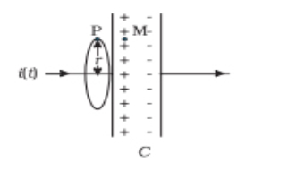
Figure 5: Parallel Plate Capacitor
The figure above shows a parallel plate capacitor connected in a circuit through which a time-dependent current i(t) flows. We will try to find the magnetic field at a point P, in the region outside the capacitor.
Consider a plane circular loop of radius r centred symmetrically with the wire. Also, the plane of the loop is perpendicular to the direction of the current carrying wire. Due to the symmetry, the magnetic field is directed along the circumference of the loop and has similar magnitude at all points on the loop.
|
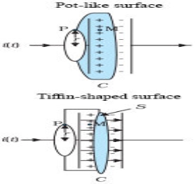
Figure 6: Magnetic field arising from time dependent electric field
However, as shown in the Figure above, when the surface is replaced by a pot-like surface where it doesn’t touch the current but has its bottom between the capacitor plates or a tiffin-shaped surface (without the lid) and Ampere’s circuital law is applied, certain contradictions arise.
These contradictions arise since no current passes through the surface and Ampere’s law does not take that scenario into consideration. This leads us to understand that there is something missing in the Ampere’s circuital law. Also, the missing term is such which enables us to get the same magnetic field at point P regardless of the surface used.
If we look at the last figure again, we can observe that the common thing that passes through the surface and between the capacitor plates is an electric field. This field is perpendicular to the surface, has the same magnitude over the area of the capacitor plates and vanishes outside it.
Hence, the electric flux through the surface is Q/ε0 (using Gauss’s law). Further, since the charge on the capacitor plates changes with time, for consistency we can calculate the current as follows
i = ε0 (dQ/dt)
This is the missing term in Ampere’s circuital law.
In simple words, when we add a term which is ε0 times the rate of change of electric flux to the total current carried by the conductors, through the same surface, then the total has the same value of current ‘i’ for all surfaces. Therefore, no contradiction is observed if we use the Generalized Ampere’s Law.
Hence, the magnitude of B at a point P outside the plates is the same at a point just inside. Now, the current carried by conductors due to the flow of charge is called ‘Conduction current’. The new term added is the current that flows due to the changing electric field and is called ‘Displacement current’ or Maxwell’s Displacement current’.
DISPLACEMENT CURRENT
Displacement current is the rate of change of electric displacement field.
The type of current which passes through a conductor is known as conduction current and is caused by the actual movement of electrons through the conductor. This type of current is mostly used in our day to day life. There is also another kind of current, which is known as displacement current. Displacement current differs from the conduction current because the displacement current does not involve electrons' movement. The displacement current has enormous importance for the propagation of electromagnetic waves. In electromagnetism, displacement current is a quantity appearing in Maxwell's equations that is defined in terms of the rate of change of electric displacement field.
Displacement current has the units of electric current density, and it has an associated magnetic field just as actual currents do.
It is mathematically represented as ID = JD S = S Where S = Area of the plate of the capacitor ID = Displacement current JD = Displacement current density D = εE where ε is permittivity of the medium
|
During the charging and discharging process of the capacitor, the electric current flows through the wires of the circuit. However, no current flow between the plates of the capacitor.
According to Ampere's law, the magnetic field should not present between the plates as there is no current, but in reality, the magnetic field exists there. Maxwell formulated this limitation of Ampere's law by adding a term in the equation of Ampere's law to solve the issue.
Maxwell predicted that the magnetic field will still exist even in the absence of conduction current, and the magnetic field may be associated with the changing electric field. This theory of Maxwell was experimentally proved.
Since the magnetic field is associated with the electric field, the general displacement current formula is given by,
This equation is the generalized formula of Maxwell-Ampere law. Displacement Current Definition The displacement current (ID) is the part which Maxwell has added to the Ampere's law. ID = ε0 ε0 = Permittivity of free space
Electric flux is the time rate change of flow of the electric field through a surface. If we take the derivative of electric flux, we get the rate of change of the electric field of a given area concerning time |
Key Takeaways
- Displacement current is the rate of change of electric displacement field.
- Displacement current differs from the conduction current because the displacement current does not involve electrons' movement.
- The displacement current has enormous importance for the propagation of electromagnetic waves.
- Displacement current has the units of electric current density, and it has an associated magnetic field just as actual currents do.
- According to Ampere's law, the magnetic field should not present between the plates as there is no current, but in reality, the magnetic field exists there.
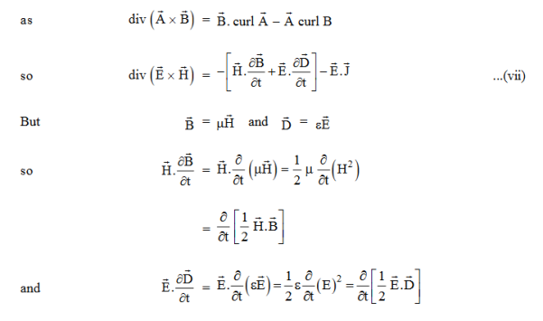
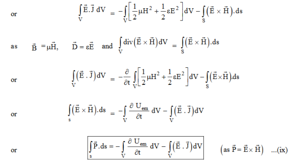
Maxwell equations are of fundamental importance since they describe the whole of classical electromagnetic phenomena. From a classical perspective, light can be described as waves of electromagnetic radiation. As such, Maxwell equations are very useful to illustrate a number of the characteristics of light including polarization. We are just to stating these equations without derivation. Since our goal is simply to apply them, the usual approach will be followed. Maxwell’s four equations are given by ∇·E = ρ/ε0 (1) ∇×E = −∂B/∂t (2) ∇×H = J + ∂D/∂t (3) ∇·B = 0 (4) These equations illustrate the unique coexistence in nature of the electric field and the magnetic field. The first two equations give the value of the given flux through a closed surface, and the second two equations give the value of a line integral around a loop. In this notation, ∇=(∂/∂x, ∂/∂y, ∂/∂z) E is the electric vector B is the magnetic induction ρ is the electric charge density j is the electric current density ε0 is the permittivity of free space c is the speed of light.
In addition to Maxwell equations, the following identities are useful:
J = σE (5) D = εE (6) B = μH (7)
Here, D is the electric displacement H is the magnetic vector σ is the specific conductivity ε is the dielectric constant (or permittivity) μ is the magnetic permeability In the Gaussian systems of units, Maxwell equations are given in the form of ∇·B=0 (8) ∇·E=4πρ (9) ∇×H=(1/c)(∂D/∂t+4πj) (10) ∇×E=−(1/c)(∂B/∂t) (11)
Free space or non-conducting medium. We know that non conducting medium means no current so conductivity is zero i.e. σ=0 So current density J=σE will also become zero as σ=0 Also free space means no charges which leads to ρ=0. These points mentioned below. (a) No condition current i.e σ=0, thus J=0 ( J=σE) For the case of no charges or currents, that is, j = 0 and ρ = 0, and a homogeneous medium. Using these the Maxwell equation can rewritten as ∇ x E= -dB/dt or ∇ x E= -μ dH/dt because B = μH (13) ∇ x H=d D/dt or ∇ x H = ε dE/dt (J=0) and D = εE (14) Maxwell's Equations are a set of 4 complicated equations that describe the world of electromagnetics. These equations describe how electric and magnetic fields propagate, interact, and how they are influenced by objects. |
Maxwell was one of the first to determine the speed of propagation of electromagnetic (EM) waves was the same as the speed of light - and hence to conclude that EM waves and visible light were really the same thing.
These equations are rules the universe uses to govern the behaviour of electric and magnetic fields. A flow of electric current will produce a magnetic field. If the current flow varies with time (as in any wave or periodic signal), the magnetic field will also give rise to an electric field. Maxwell's Equations shows that separated charge (positive and negative) gives rise to an electric field - and if this is varying in time as well will give rise to a propagating electric field, further giving rise to a propagating magnetic field.
From a classical perspective, light can be described as waves of electromagnetic radiation. As such, Maxwell equations are very useful to illustrate a number of the characteristics of light including polarization.
The First Maxwell’s equation (Gauss’s law for electrostatics)
Gauss' Law is the first of Maxwell's Equations which dictates how the Electric Field behaves around electric charges. Gauss' Law can be written in terms of the Electric Flux Density and the Electric Charge Density as:
∇·E = ρ/ε0
0r
∇·D = ρ
Hence, Gauss' law is a mathematical statement that the total Electric Flux exiting any volume is equal to the total charge inside. Hence, if the volume in question has no charge within it, the net flow of Electric Flux out of that region is zero. If there is positive charge within a volume, then there exists a positive amount of Electric Flux exiting any volume that surrounds the charge. If there is negative charge within a volume, then there exists a negative amount of Electric Flux exiting (i.e. the Electric Flux enters the volume).
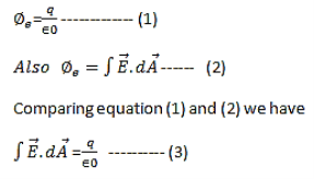
The Gauss’s law states that flux passing through any closed surface is equal to 1/ε0 times the total charge enclosed by that surface.
Integral form of Maxwell’s 1st equation
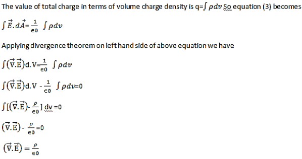
Maxwell’s first equation in differential form It is called the differential form of Maxwell’s 1st equation.
|
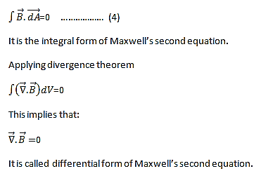
The Second Maxwell’s equation (Gauss’s law for magnetism)
The Gauss’s law for magnetism states that net flux of the magnetic field through a closed surface is zero because monopoles of a magnet do not exist.
we know that Gauss' Law for Electric Fields states that the divergence of the Electric Flux Density D is equal to the volume electric charge density. But the second equation, Gauss' Magnetism law states that the divergence of the Magnetic Flux Density (B) is zero. Why? Why isn't the divergence of B equal to the magnetic charge density? Well - it is. But it just so happens that no one has ever found magnetic charge - not in a laboratory or on the street or on the subway. And therefore, until this hypothetical magnetic charge is found, we set the right side of Gauss' Law for Magnetic Fields to zero: ∇·B = 0 Now, you may have played with magnets when you were little, and these magnetic objects attracted other magnets similar to how electric charges repel or attract like electric charges. However, there is something special about these magnets - they always have a positive and negative end. This means every magnetic object is a magnetic dipole, with a north and South Pole. No matter how many times you break the magnetic in half, it will just form more magnetic dipoles. Gauss' Law for Magnetism states that magnetic monopoles do not exist - or at least we haven't found them yet. |
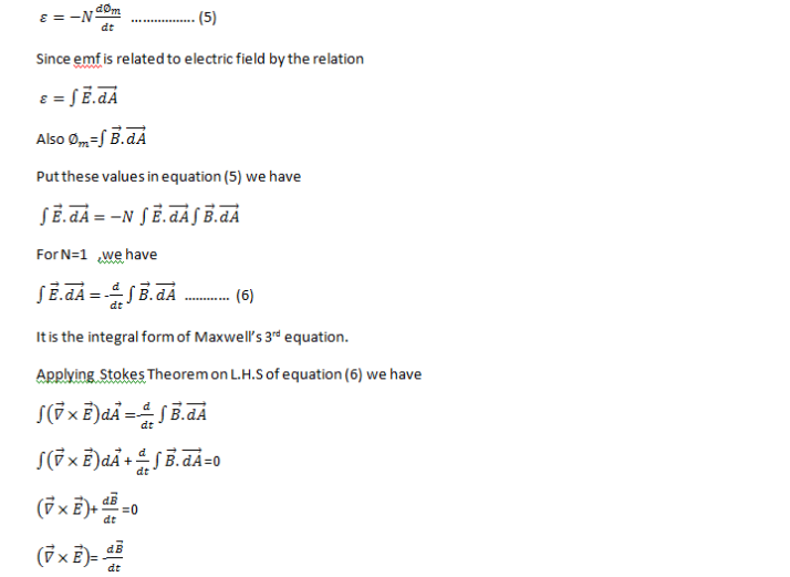
Maxwell’s Third equation (Faraday's Law)
Faraday figured out that a changing Magnetic Flux within a circuit (or closed loop of wire) produced an induced EMF, or voltage within the circuit. Maxwell gives his second equation from this. Faraday's Law tells us that a magnetic field that is changing in time will give rise to a circulating E-field. This means we have two ways of generating E-fields - from Electric Charges (or flowing electric charge, current) or from a magnetic field that is changing. ∇×E = −∂B/∂t According to Faraday’s law of electromagnetic induction
|
Maxwell’s fourth equation (Ampere's Law)
Ampere's Law tells us that a flowing electric current gives rise to a magnetic field that circles the wire. In addition to this, it also says that an Electric Field that is changing in time gives rise to a magnetic field that encircles the E-field - this is the Displacement Current term that Maxwell himself introduced. This means there are 2 ways to generate a solenoidal (circulating) H-field - a flowing electric current or a changing Electric Field. Both give rise to the same phenomenon. The modified form of ampere Law is given by H.dL=(J+dD/dt) Take integration on both sides we have ∫H.dL=∫(J+dD/dt).dS Apply stoke’s theorem to L.H.S. of above equation, we get ∫( ∇xH).dS=∫ H.dL Now the above equation is written as ∫( ∇xH).dS =∫(J+dD/dt).dS By cancelling the surface integral on both sides we have ∇xH =J+dD/dt Which is the differential form of Maxwell’s equation. This can also be written in the form B The Ampere-Maxwell Law
Begin with the Ampere-Maxwell law in integral form.
Invoke Stokes' theorem.
Set the equation to 0. |
PHYSICAL SIGNIFICANCE OF EACH EQUATION
Physical significance of Maxwell’s Ist equation
∇·E = ρ/ε0
According to this total electric flux through any closed surface is 1/0 times the total charge enclosed by the closed surfaces, representing Gauss's law of electrostatics, As this does not depend on time, it is a steady state equation. Here for positive , divergence of electric field is positive and for negative divergence is negative. It indicates that is scalar quantity.
Physical significance of Maxwell’s 2nd equation
∇·B = 0
It represents Gauss law of magnetostatic as ∇·B = 0 resulting that isolated magnetic poles or magnetic monopoles cannot exist as they appear only in pairs and there is no source or sink for magnetic lines of forces. It is also independent of time i.e. steady state equation.
Physical significance of Maxwell’s 3rd equation
∇×E = −∂B/∂t
It shows that with time varying magnetic flux, electric field is produced in accordance with Faraday is law of electromagnetic induction. This is a time dependent equation.
Physical significance of Maxwell’s 4th equation
∇×H = J + ∂D/∂t
This is a time dependent equation which represents the modified differential form of Ampere's circuital law according to which magnetic field is produced due to combined effect of conduction current density and displacement current density.
Key Takeaways
- The First Maxwell’s equation is known as Gauss’s law for electrostatics. It is given by ∇·E = ρ/ε0 . According to this total electric flux through any closed surface is 1/0 times the total charge enclosed by the closed surfaces, representing Gauss's law of electrostatics,
- The Second Maxwell’s equation is known as Gauss’s law for magnetism. . It is given by ∇·B = 0. The Gauss’s law for magnetism states that net flux of the magnetic field through a closed surface is zero because monopoles of a magnet do not exist.
- Maxwell’s Third equation is known as Faraday's Law. It is given by ∇×E = −∂B/∂t. Faraday figured out that a changing Magnetic Flux within a circuit (or closed loop of wire) produced an induced EMF, or voltage within the circuit.
- Maxwell’s fourth equation is known as Ampere's Law. It is given by ∇×H = J + ∂D/∂t . Ampere’s Law tells us that a flowing electric current give rise to a magnetic field that circles the wire. In addition to this, it also says that an Electric Field that is changing in time gives rise to a magnetic field that encircles the E-field - this is the Displacement Current.
Key Takeaways
References
- David Griffiths, ‘Introduction to Electrodynamics’.
- Prabir K. Basu & Hrishikesh Dhasmana, ‘Electromagnetic Theory’.
- Khunita, ‘Fundamentals of Electromagnetic Theory’.
- S.P. Puri, ‘Classical Electrodynamics’, Tata McGraw Hill
- Gupta & Gaur, ‘Engineering Physics’, Dhanpat Rai.
- Malik and Singh, ‘Engineering Physics’, Tata McGraw Hill.
- Naidu, ‘Engineering Physics’, Pearson.
