UNIT – 4
MAGNETIC MATERIALS & SUPERCONDUCTIVITY
Magnetic materials are classified as follows:
- Diamagnetic
- Paramagnetic
- Ferromagnetic
- Anti-Ferro magnetic
- Ferrimagnetism
Diamagnetic
The orbital motion of electrons around the nucleus produces a magnetic field perpendicular to the plane of the orbit. Thus each electron orbit has a finite orbital magnetic dipole moment. Since the orbital planes are oriented randomly, the vector sum of magnetic moments is zero and there is no resultant magnetic moment for each atom.
In the presence of an external magnetic field, some electrons are speeded up and some are slowed down. The electrons whose moments were anti-parallel are speeded up according to Lenz’s law and this produces an induced magnetic moment in a direction opposite to the field. The induced moment disappears as soon as the external field is removed.
When placed in a non-uniform magnetic field, the interaction between the induced magnetic moment and the external field creates a force that tends to move the material from the stronger part to the weaker part of the external field. It means that diamagnetic material is repelled by the field.
This action is called diamagnetic action and such materials are known as diamagnetic materials. Examples: Bismuth, Copper, and Water, etc.
The properties of diamagnetic materials are
- Magnetic susceptibility is negative.
- Relative permeability is slightly less than unity.
- The magnetic field lines are repelled or expelled by diamagnetic materials when placed in a magnetic field.
- Susceptibility is nearly temperature independent.
- Examples: Cu, Au, Zn, H20, Bi, etc. organic materials
Paramagnetic materials
In some magnetic materials, each atom or molecule has a net magnetic dipole moment which is the vector sum of orbital and spin magnetic moments of electrons. Due to the random orientation of these magnetic moments, the net magnetic moment of the materials is zero.
In the presence of an external magnetic field, the torque acting on the atomic dipoles will align them in the field direction. As a result, there is a net magnetic dipole moment induced in the direction of the applied field. The induced dipole moment is present as long as the external field exists.
The properties of paramagnetic materials are:
- Magnetic susceptibility is positive and small.
- Relative permeability is greater than unity.
- The magnetic field lines are attracted to the paramagnetic materials when placed in a magnetic field.
- Susceptibility is inversely proportional to temperature.
Ferromagnetic materials
An atom or a molecule in a ferromagnetic material possesses a net magnetic dipole moment as in a paramagnetic material. A ferromagnetic material is made up of smaller regions, called ferromagnetic domain. Within each domain, the magnetic moments are spontaneously aligned in a direction. This alignment is caused by strong interaction arising from electron spin which depends on the inter-atomic distance. Each domain has net magnetization in a direction. However, the direction of magnetisation varies from domain to domain and thus net magnetisation of the specimen is zero.
In the presence of an external magnetic field, two processes take place
1. The domains having magnetic moments parallel to the field grow in size
2. The other domains (not parallel to the field) are rotated so that they are aligned with the field.
As a result of these mechanisms, there is a strong net magnetisation of the material in the direction of the applied field
When placed in a non-uniform magnetic field, the ferromagnetic materials will have a strong tendency to move from the weaker to the stronger part of the field. Materials that exhibit strong magnetism in the direction of the applied field are called ferromagnetic materials. Examples: Iron, Nickel, and Cobalt.
The properties of ferromagnetic materials are:
- Magnetic susceptibility is positive and large.
- Relative permeability is large.
- The magnetic field lines are strongly attracted to the ferromagnetic materials when placed in a magnetic field.
- Susceptibility is inversely proportional to temperature.
Antiferromagnetism
In the periodic table, the only element exhibiting antiferromagnetism at room temperature is chromium. Antiferromagnetic materials are very similar to ferromagnetic materials but the exchange interaction between neighbouring atoms leads to the anti-parallel alignment of the atomic magnetic moments. Therefore, the magnetic field cancels out and the material appears to behave in the same way as a paramagnetic material. Like ferromagnetic materials, these materials become paramagnetic above a transition temperature, known as the Neel temperature, TN. (Cr: TN=37ºC).
The properties of antiferromagnetic materials are:
- They have permanent magnetic dipoles
- They do not possess a permanent magnetic dipole moment. Since in the absence of field, they have no spontaneous magnetization due to anti-parallel spin
- The relative permeability μr>1
- Susceptibility χ is small but negative
- 𝜒depends on temperature
Ferrimagnetism
Ferrimagnetism is only observed in compounds, which have more complex crystal structures than pure elements. Within these materials the exchange interactions lead to parallel alignment of atoms in some of the crystal sites and anti-parallel alignment of others. The material breaks down into magnetic domains, just like a ferromagnetic material and the magnetic behaviour is also very similar, although ferrimagnetic materials usually have lower saturation magnetisations. For example in Barium ferrite (BaO.6Fe2O3) the unit cell contains 64 ions of which the barium and oxygen ions have no magnetic moment, 16 Fe3+ ions have moments aligned parallel and 8 Fe3+ aligned anti-parallel giving a net magnetisation parallel to the applied field, but with a relatively low magnitude as only ⅛ of the ions contribute to the magnetisation of the material.
The properties of ferrimagnetic materials are:
- They have permanent magnetic dipoles.
- They possess permanent magnetic diploe moment. Also in the absence of field they have spontaneous magnetization. Since spin is anti-parallel but of different magnitudes
- The relative permeability μr>>1
- Susceptibility is large and positive
- 𝜒 depend on temperature
Key Takeaways
- Magnetic materials are classified as Diamagnetic, Paramagnetic, Ferromagnetic, Anti-Ferro magnetic.
- Diamagnetic material is repelled by the field and having negative Magnetic susceptibility.
- In paramagnetic materials the magnetic field lines are attracted to the paramagnetic materials when placed in a magnetic field. Magnetic susceptibility is positive and small.
- Materials that exhibit strong magnetism in the direction of the applied field are called ferromagnetic materials. Magnetic susceptibility is positive and large.
- Antiferromagnetic materials are very similar to ferromagnetic materials but the exchange interaction between neighbouring atoms leads to the anti-parallel alignment of the atomic magnetic moments. Susceptibility χ is small but negative
- Ferrimagnetism is only observed in compounds, which have more complex crystal structures than pure elements. 𝜒 depend on temperature
Weiss theory of ferromagnetism is also called domain theory of ferromagnetism. The characteristic feature of ferromagnetic order is spontaneous magnetisation due to spontaneous alignment of atomic magnetic moments, which disappears on heating above a critical temperature known as the Curie point. The magnetization tends to lie along certain easy directions determined by crystal structure (magnetocrystalline anisotropy) or sample shape.
Inside an individual domain a spontaneous alignment of the magnetic moments
Occurs. Then assume the alignment of any individual magnetic moment is due to
An internal magnetic field which arises from all the other magnetic moment
Present in the domain
Weiss (1907) supposed that in addition to any externally applied field there is an
Internal molecular’ field in a ferromagnet proportional to its magnetization. The
Origin of these huge fields remained a mystery until Heisenberg introduced the
Idea of the exchange interaction in 1928.
The magnitude of this internal magnetic field is assumed to be proportional to the
Magnetisation M of the sample,
Total field B = Bext + Bint = Bext +μ0 Hint
B = Bext +μ0  …………. (1)
Here  is the constant of proportionality is called Weiss Molecular field constant.
Weiss incorporated this “molecular field” into the existing treatment of the
Paramagnet.
His theory has considerable success in correctly predicting the properties of the ferromagnet. It is capable of extension to all the other types of magnetic materials that show co-operative behaviour
From the quantum treatment of the paramagnet we obtain, where M is a function of temperature T through,
 …………. (2)
So we can write,
 …………. (3)
 …………. (4)
Now, as T→ 0, y→∞, BJ(y)→ 1 so that the saturation magnetisation M(0) is equal to,
M(T) = NμJ …………. (5)
 = BJ(y) …………. (6)
But for the ferromagnet, we must add the molecular field term to y. So substitute (1) into (2) to get
 …………. (7)
However, we want the spontaneous magnetisation so we let Bext→ 0 and write M = M(T) explicitly that is,
 …………. (8)
So rearranging, and using equation (5) for M(0) we get,
 …………. (9)
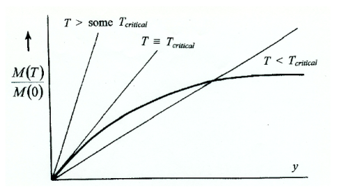
Figure 1: Variation of M(T)/ M(0)
1) T > some Tcritical M(T)/M(0)≡ 0 is the only solution
2) T ≡ Tcritical the straight line is a tangent to BJ(y) at the origin, - still only one solution M(T)/M(0)≡ 0
3) T < Tcritical two solutions, M(T)/M(0)≡ 0 as before M(T)/M(0) = real [actual value of M(T)]
Temperature variation of magnetisation M of a ferromagnet
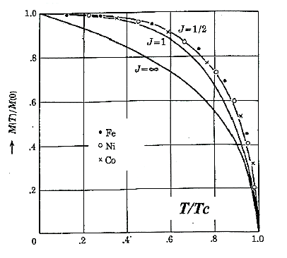
Figure 2: Temperature variation of magnetisation M of a ferromagnet
Evaluation of the critical temperature (Curie temperature)
At small values of y we can expand BJ(y) as,
 …………. (10)
Which is also a straight line, - so equating these two gives,
 …………. (11)
Where
 …………. (12)
Thus we have
 …………. (13)
Thus
Tc = Tc( ) …………. (14)
The larger the Weiss Molecular Field constant γ the higher the Curie temperature TC.
Successes of the Weiss Molecular Field model
- It gives a good account of the spontaneous magnetisation of the feromagnet, the temperature variation of magnetisation, M(T)/M(0)
- The magnetic susceptibility above TC - called the Curie Weiss Law.
We have seen that if we assume that the internal magnetic field is proportional to the magnetisation of the sample, we can get a spontaneous magnetization for temperatures less than the Curie temperature. We also find the larger the field constant (relating internal field to magnetization), the higher the Curie temperature.
Key Takeaways
- Weiss theory of ferromagnetism is also called domain theory of ferromagnetism.
- The characteristic feature of ferromagnetic order is spontaneous magnetisation due to spontaneous alignment of atomic magnetic moments, which disappears on heating above a critical temperature known as the Curie point.
- It gives a good account of the spontaneous magnetisation of the ferromagnet, the temperature variation of magnetisation, M(T)/M(0)
This magnetic domain theory for ferromagnetic was first proposed by Pierre-Ernest Weiss in 1906. The microscopic ordering of electron spins characteristic of ferromagnetic materials leads to the formation of regions of magnetic alignment called domains.
The magnetic moments of atoms dictate the magnetic properties of a material. In ferromagnetic materials, long-range alignments of magnetic moments, called domains, contain magnetic moments that all point in the same direction.
However, if material were to have all of its magnetic moments pointed in the same direction, this would create a very large external magnetic field. This field is not energetically minimizing as it stores large amounts of magnetostatic energy in the field.
Thus, for the system to minimize its internal energy, it must minimize the external field produced. To do this, the material creates different domains within itself to redirect the magnetic field. The regions in-between these domains are known as domain walls.
Interactions of a material's exchange interaction, magnetocrystalline anisotropy, and minimization of external magnetic field determine the domain structure of a material.
The magnetisation within the domain is saturated and will always lie in the easy direction of magnetisation when there is no externally applied field. The direction of the domain alignment across a large volume of material is more or less random and hence the magnetisation of a specimen can be zero.
Magnetic domains exist to reduce the energy of the system. A uniformly magnetized specimen as shown in figure 3(a) has large magnetostatic energy associated with it. This is the result of the presence of magnetic free poles at the surface of the specimen generating a demagnetizing field, Hd. From the convention adopted for the definition of the magnetic moment for a magnetic dipole the magnetisation within the specimen points from the south pole to the north pole, while the direction of the magnetic field points from north to south. Therefore, the demagnetizing field is in opposition to the magnetisation of the specimen. The magnitude of Hd is dependent on the geometry and magnetisation of the specimen.
In general, if the sample has a high length to diameter ratio (and is magnetized in the long axis) then the demagnetizing field and the magnetostatic energy will be low.
The break-up of the magnetisation into two domains as illustrated in figure 3(b) reduces the magnetostatic energy by half. In fact, if the magnet breaks down into N domains then the magnetostatic energy is reduced by a factor of 1/N, hence figure 3(c) has a quarter of the magnetostatic energy of figure 3(a). Figure 3(d) shows a closure domain structure where the magnetostatic energy is zero, however, this is only possible for materials that do not have a strong uniaxial anisotropy, and the neighbouring domains do not have to be at 180º to each other.
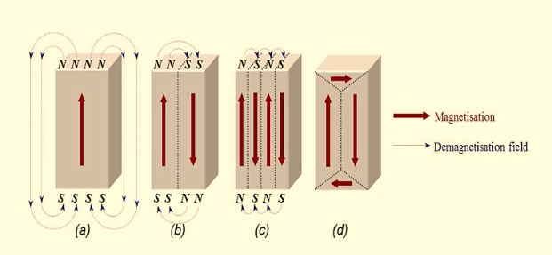
Figure 3: Schematic illustration of the break-up of magnetisation into domains: (a) single domain; (b) two domains; (c) four domains; (d) closure domains.
The introduction of a domain raises the overall energy of the system, therefore the division into domains only continues while the reduction in magnetostatic energy is greater than the energy required to form the domain wall.
The energy associated with a domain wall is proportional to its area. The schematic representation of the domain wall, shown in figure 4, illustrates that the dipole moments of the atoms within the wall are not pointing in the easy direction of magnetisation and hence are in a higher energy state.
Also, the atomic dipoles within the wall are not at 180º to each other and so the exchange energy is also raised within the wall. Therefore, the domain wall energy is an intrinsic property of material depending on the degree of magnetocrystalline anisotropy and the strength of the exchange interaction between neighbouring atoms. The thickness of the wall will also vary in relation to these parameters, as a strong magnetocrystalline anisotropy will favour a narrow wall, whereas a strong exchange interaction will favour a wider wall.
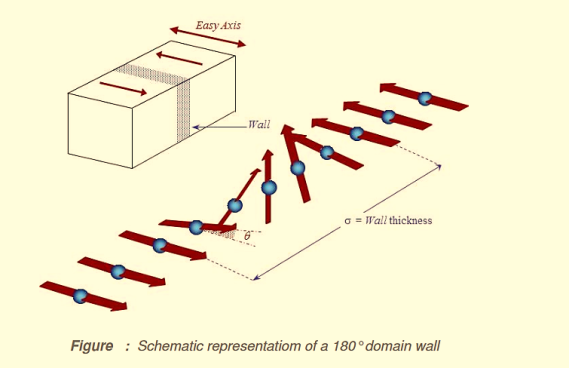
Figure 4: Schematic representation of a 180o domain wall
Minimum energy can therefore be achieved with a specific number of domains within a specimen. This number of domains will depend on the size and shape of the sample (which will affect the magnetostatic energy) and the intrinsic magnetic properties of the material (which will affect the magnetostatic energy and the domain wall energy).
The main implication of the domains is that there is already a high degree of magnetization in ferromagnetic materials within individual domains, but that in the absence of external magnetic fields those domains are randomly oriented. A modest applied magnetic field can cause a larger degree of alignment of the magnetic moments with the external field, giving a large multiplication of the applied field.
These illustrations of domains are conceptual only and not meant to give an accurate scale of the size or shape of domains.
The microscopic evidence about magnetization indicates that the net magnetization of ferromagnetic materials in response to an external magnetic field may occur more by the growth of the domains parallel to the applied field at the expense of other domains rather than the reorientation of the domains themselves as implied in the sketch.
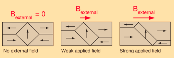
Figure 5: Domain Alignment
The internal magnetic fields which come from the long-range ordering of the electron spins are much stronger, sometimes hundreds of times stronger, than the external magnetic fields required to produce these changes in domain alignment.
Key Takeaways
- The microscopic ordering of electron spins characteristic of ferromagnetic materials leads to the formation of regions of magnetic alignment called domains.
- For the system to minimize its internal energy, it must minimize the external field produced. To do this, the material creates different domains within itself to redirect the magnetic field. The regions in-between these domains are known as domain walls.
- This number of domains will depend on the size and shape of the sample and the intrinsic magnetic properties of the material.
Magnetic Hysteresis
The lag or delay of a magnetic material known commonly as Magnetic Hysteresis relates to the magnetization properties of a material by which it first becomes magnetized and then de-magnetized.
The set of magnetization curves, M above represents an example of the relationship between B and H for soft-iron and steel cores but every type of core material will have its own set of magnetic hysteresis curves. You may notice that the flux density increases in proportion to the field strength until it reaches a certain value where it cannot increase any more becoming almost level and constant as the field strength continues to increase.
This is because there is a limit to the amount of flux density that can be generated by the core as all the domains in the iron are perfectly aligned. Any further increase will not affect the value of M, and the point on the graph where the flux density reaches its limit is called Magnetic Saturation also known as Saturation of the Core and in our simple example above the saturation point of the steel, the curve begins at about 3000 ampere-turns per metre.
As the magnetic field strength, ( H ) increases these molecular magnets become more and more aligned until they reach perfect alignment producing maximum flux density, and an increase in the magnetic field strength due to an increase in the electrical current flowing through the coil will have little or no effect.
Retentivity
Let’s assume that we have an electromagnetic coil with a high field strength due to the current flowing through it and that the ferromagnetic core material has reached its saturation point, maximum flux density. If we now open a switch and remove the magnetizing current flowing through the coil we would expect the magnetic field around the coil to disappear as the magnetic flux reduced to zero.
However, the magnetic flux does not completely disappear as the electromagnetic core material still retains some of its magnetism even when the current has stopped flowing in the coil. This ability for a coil to retain some of its magnetism within the core after the magnetization process has stopped is called Retentivity or remanence, while the amount of flux density remaining in the core is called Residual Magnetism, BR.
The reason for this that some of the tiny molecular magnets do not return to a completely random pattern and still point in the direction of the original magnetizing field giving them a sort of “memory”. Some ferromagnetic materials have a high retentivity (magnetically hard) making them excellent for producing permanent magnets.
While other ferromagnetic materials have low retentivity (magnetically soft) making them ideal for use in electromagnets, solenoids, or relays. One way to reduce this residual flux density to zero is by reversing the direction of the current flowing through the coil, thereby making the value of H, the magnetic field strength negative. This effect is called a Coercive Force, HC.
If this reverse current is increased further the flux density will also increase in the reverse direction until the ferromagnetic core reaches saturation again but in the reverse direction from before. Reducing the magnetizing current, i once again to zero will produce a similar amount of residual magnetism but in the reverse direction.
Then by constantly changing the direction of the magnetizing current through the coil from a positive direction to a negative direction, as would be the case in an AC supply, a Magnetic Hysteresis loop of the ferromagnetic core can be produced.
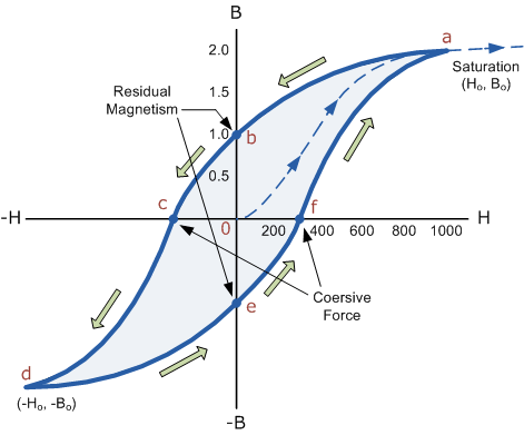
Figure 6: B-H Curve
The B-H Curve or Magnetic Hysteresis loop above shows the behaviour of a ferromagnetic core graphically as the relationship between B and H is non-linear.
Starting with an unmagnetized core both B and H will be at zero, point 0 on the magnetization curve.
If the magnetization current, i is increased in a positive direction to some value the magnetic field strength H increases linearly with i and the flux density B will also increase as shown by the curve from point 0 to point a as it heads towards saturation.
Now if the magnetizing current in the coil is reduced to zero, the magnetic field circulating around the core also reduces to zero. However, the coils magnetic flux will not reach zero due to the residual magnetism present within the core and this is shown on the curve from point a to point b.
To reduce the flux density at point b to zero we need to reverse the current flowing through the coil. The magnetising force which must be applied to null the residual flux density is called a “Coercive Force”. This coercive force reverses the magnetic field re-arranging the molecular magnets until the core becomes unmagnetised at point c.
An increase in this reverse current causes the core to be magnetised in the opposite direction and increasing this magnetisation current further will cause the core to reach its saturation point but in the opposite direction, point d on the curve.
This point is symmetrical to point b. If the magnetising current is reduced again to zero the residual magnetism present in the core will be equal to the previous value but in reverse at point e.
Again reversing the magnetising current flowing through the coil this time into a positive direction will cause the magnetic flux to reach zero, point f on the curve and as before increasing the magnetisation current further in a positive direction will cause the core to reach saturation at point a.
Then the B-H curve follows the path of a-b-c-d-e-f-a as the magnetising current flowing through the coil alternates between a positive and negative value such as the cycle of an AC voltage. This path is called a B-H Curve or Magnetic Hysteresis Loop.
The effect of magnetic hysteresis shows that the magnetisation process of a ferromagnetic core and therefore the flux density depends on which part of the curve the ferromagnetic core is magnetised on as this depends upon the circuits past history giving the core a form of “memory”. Then ferromagnetic materials have memory because they remain magnetised after the external magnetic field has been removed.
However, soft ferromagnetic materials such as iron or silicon steel have very narrow magnetic hysteresis loops resulting in very small amounts of residual magnetism making them ideal for use in relays, solenoids, and transformers as they can be easily magnetised and demagnetised.
Since a coercive force must be applied to overcome this residual magnetism, work must be done in closing the hysteresis loop with the energy being used being dissipated as heat in the magnetic material. This heat is known as hysteresis loss, the amount of loss depends on the material’s value of coercive force.
By adding additives to the iron metal such as silicon, materials with a very small coercive force can be made that have a very narrow hysteresis loop. Materials with narrow hysteresis loops are easily magnetised and demagnetised and known as soft magnetic materials.
Magnetic Hysteresis Loops for Soft and Hard Materials
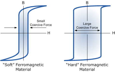
Figure 7: Magnetic Hysteresis Loops for Soft and Hard Materials
Magnetic Hysteresis results in the dissipation of wasted energy in the form of heat with the energy wasted being in proportion to the area of the magnetic hysteresis loop. Hysteresis losses will always be a problem in AC transformers where the current is constantly changing direction and thus the magnetic poles in the core will cause losses because they constantly reverse direction.
Rotating coils in DC machines will also incur hysteresis losses as they are alternately passing north the south magnetic poles. As said previously, the shape of the hysteresis loop depends upon the nature of the iron or steel used and in the case of iron which is subjected to massive reversals of magnetism, for example, transformer cores, the B-H hysteresis loop must be as small as possible.
Key Takeaways
- The lag or delay of a magnetic material known commonly as Magnetic Hysteresis relates to the magnetization properties of a material by which it first becomes magnetized and then de-magnetized.
- There is a limit to the amount of flux density that can be generated by the core as all the domains in the iron are perfectly aligned. Any further increase will not affect the value of M, and the point on the graph where the flux density reaches its limit is called Magnetic Saturation also known as Saturation of the Core.
- This ability for a coil to retain some of its magnetism within the core after the magnetization process has stopped is called Retentivity or remanence, while the amount of flux density remaining in the core is called Residual Magnetism, BR.
- One way to reduce this residual flux density to zero is by reversing the direction of the current flowing through the coil, thereby making the value of H, the magnetic field strength negative. This effect is called a Coercive Force, HC.
- Materials with narrow hysteresis loops are easily magnetised and demagnetised and known as soft magnetic materials.
Ferrites are ferromagnetic material containing predominantly oxides iron along with other oxides of barium, strontium, manganese, nickel, zinc, lithium and cadmium.
Ferrimagnetism is only observed in compounds, which have more complex crystal structures than pure elements. Within these materials the exchange interactions lead to parallel alignment of atoms in some of the crystal sites and anti-parallel alignment of others. The material breaks down into magnetic domains, just like a ferromagnetic material and the magnetic behaviour is also very similar, although ferrimagnetic materials usually have lower saturation magnetisations. For example in Barium ferrite (BaO.6Fe2O3) the unit cell contains 64 ions of which the barium and oxygen ions have no magnetic moment, 16 Fe3+ ions have moments aligned parallel and 8 Fe3+ aligned anti-parallel giving a net magnetisation parallel to the applied field, but with a relatively low magnitude as only ⅛ of the ions contribute to the magnetisation of the material.
At high frequency metallic soft magnetic materials simply cannot be used due to the eddy current losses. Therefore, soft ferrites, which are ceramic insulators, become the most desirable material. These materials are ferrimagnetic with a cubic crystal structure and the general composition MO.Fe2O3, where M is a transition metal such as nickel, manganese or zinc.
MnZn ferrite, sold commercially as ferroxcube, can be used at frequencies up to 10MHz, for example in telephone signal transmitters and receivers and in switch mode power supplies (also referred to as DC-DC converters). For this type of application the driving force to increase frequency is to allow miniaturisation. Additionally, part of the family of soft ferrites, are the microwave ferrites, e.g. Yttrium iron garnet. These ferrites are used in the frequency range from 100MHz to 500GHz, for waveguides for electromagnetic radiation and in microwave devices such as phase shifters.
Garnet ferrites have the structure of the silicate mineral garnet and the chemical formula M3(Fe5O12), where M is yttrium or a rare-earth ion. In addition to tetrahedral and octahedral sites, such as those seen in spinels, garnets have dodecahedral (12-coordinated) sites. The net ferrimagnetism is thus a complex result of antiparallel spin alignment among the three types of sites. Garnets are also magnetically hard.
APPLICATIONS
Ferrites are ideally suited for making device like inductor core, circulators, and memory devices and also for various microwave application.
The earliest ferrite was naturally occurring magnetite. The first application of ferrites were needles magnetized by the magnetite which functioned as compasses and allowed mariners to find North without the use of the stars. .However, magnetite was found to have poor magnetic properties and was not useful for magnetic applications.
The first large-scale applications for ferrites were in the television industry where large tonnages were used for the TV tube deflection yokes and the high voltage fly back transformers.
These are used in radar, satellite communications, memory and computer applications, there has been corresponding growth in consumer markets in radio, television, video tape recorders and finally, the internet.
As the markets have changed, the requirements of ferrites have changed as well. From the old analog circuits to the newer digital ones, there arose the need for high frequency switched mode power supplies to power computers and other digital devices. Another strong market for ferrites is in the automotive industry and most recently in hybrid cars.
Key Takeaways
- Ferrites are ferromagnetic material containing predominantly oxides iron along with other oxides of barium, strontium, manganese, nickel, zinc, lithium and cadmium.
- Garnet ferrites have the structure of the silicate mineral garnet and the chemical formula M3(Fe5O12), where M is yttrium or a rare-earth ion.
- Ferrites are ideally suited for making device like inductor core, circulators, and memory devices and also for various microwave application.
It was first discovered by the Dutch physicist Heike Kamerlingh Onnes, who was the first to liquefy helium (which boils at 4.2 Kelvin at standard pressure).
In 1911 Kamerlingh Onnes and one of his assistants discovered the phenomenon of superconductivity while studying the resistance of metals at low temperatures. They studied mercury because very pure samples could easily be prepared by distillation. The historic measurement of superconductivity in mercury is shown in Figure.
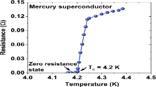
Figure 8: Measurement of superconductivity in mercury
The electrical resistance of mercury decreased steadily upon cooling, but dropped suddenly at 4.2 K, and became undetectably small.
Transition Temperature or Critical Temperature Tc
The temperature at which the electrical resistivity of the material suddenly drops to zero and the material changes from normal conductor to a superconductor is called the transition temperature or critical temperature Tc.
Soon after this discovery, many other elemental metals were found to exhibit zero resistance when their temperatures were lowered below a certain characteristic temperature of the material, called the critical temperature, Tc.
Superconductivity
The ability of certain metals, their compounds, and alloys to conduct electricity with zero resistance at very low temperatures is called superconductivity. The materials which exhibit this property are called superconductors.
Properties
The following properties are shown by superconductors.
- It is a low-temperature phenomenon.
- The electrical resistivity drops to zero.
- The conductivity becomes infinity.
- The transition temperature is different for different substances.
- Material having high normal resistivity exhibit superconductivity.
- Materials for which ρZ= 106 (where Z is an atomic number and ρ is resistivity) show superconductivity.
- Superconductivity is very sharp for the chemically pure and structurally perfect specimen.
- Ferromagnetic and Antiferromagnetic materials are not superconductors.
- Below the transition temperature, the magnetic flux lines are rejected out of the superconductors.
- Generally, Superconducting elements lie in the inner columns of the periodic table.
- Those metallic elements having their valence electrons lies between 2 to 8 exhibit superconductivity.
- Below the transition temperature, the specific heat curve is discontinuous.
- There is a discontinuous change in specific heat.
- There are small changes in the volume and thermal conductivity of the material.
Key Takeaways
- The ability of certain metals, their compounds, and alloys to conduct electricity with zero resistance at very low temperatures is called superconductivity.
- The temperature at which the electrical resistivity of the material suddenly drops to zero and the material changes from normal conductor to a superconductor is called the transition temperature or critical temperature Tc.
- It is a low-temperature phenomenon. The electrical resistivity drops to zero and conductivity becomes infinity.
In 1933, Walter Meissner and Robert Ochsenfeld discovered a magnetic phenomenon that showed that superconductors are not just perfect conductors.
When a weak magnetic is applied to a superconducting specimen at a temperature below transition temperature Tc the magnetic flux lines are expelled. This phenomenon is called the Meissner effect.
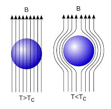
Figure 9: Meissner Effect
Under normal state the magnetic induction inside the specimen is
B = μ0(H+I)
Where H is the external applied magnetic field and I is the magnetization produced inside the specimen.
When the specimen is in superconducting state B=0 (Meissner effect)
B = μ0(H+I)
0 = μ0(H+I)
H= -I
χ = H/I =-1
Thus the material acts as a perfectly diamagnetic because for diamagnetic material susceptibility χ = -1.
Let us consider a superconducting material is in a normal state. From ohms law, the electric field E=Jρ
On cooling the material to its transition temperature ρ tends to zero. If J is held finite E must be zero. From Maxwell’s equations
∇ × E = - dB / dt
Under superconducting condition
Since E is zero
DB/dt =0
Or B=constant.
This means that the magnetic flux passing through the specimen should not change on cooling to the transition temperature. The Meissner effect contradicts the result.
Application of Meissner Effect
This effect of superconductivity is used in magnetic levitation which is the base of modern high-speed bullet trains. In the superconducting state (phase), due to expulsion of the external magnetic field, the sample of superconducting material levitates above the magnet or vice-versa. Modern high-speed bullet trains use the phenomenon of magnetic levitation.
Key Takeaways
- When a weak magnetic is applied to a superconducting specimen at a temperature below transition temperature Tc the magnetic flux lines are expelled. This phenomenon is called the Meissner effect.
- This effect of superconductivity is used in magnetic levitation which is the base of modern high-speed bullet trains.
Types of Superconductors
Based on the diamagnetic response superconductors can be classified into two types, they are
1. Type I superconductors
2. Type II superconductors.
- Type I superconductors
Superconductors that follows a complete Meissner effect is called type I superconductors. It is also known as soft superconductors.
When the magnetic field strength is gradually increased from its initial value H < HC at HC the diamagnetism is abruptly disappeared and the transition from the superconducting state to a normal state is sharp as shown in the figure. These superconductors are known as soft superconductors.
Examples: - Al, Zn, Hg, and Sn
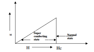
Figure 10: Type I superconductors
2. Type II superconductors
Superconductors which does not follow the complete Meissner effect are called type I superconductors. It is also known as hard superconductors.
In type II superconductors, the specimen is in a pure superconducting state up to the field HC1 (lower critical field) when the field is increased beyond HC2 (upper critical state) the magnetic flux lines start penetrating.
The specimen is in a mixed state between HC1 and HC2. Above HC2, the specimen is in a normal state. This means that the Meissner effect is incomplete in the region between HC1 and HC2. This region is known as the vertex region. These superconductors are known as hard superconductors.
Examples: - Zr, Nb
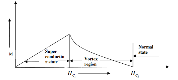
Figure 11: Type II superconductors
Differences between type I and Type II superconductor
Type I superconductor | Type II superconductor |
1. It follows the complete Meissner effect. | 1. It does not follow the complete Meissner effect |
2. It has single critical field valueHC | 2. It has two critical field values HC1 and HC2. |
3. There no mixed state. | 3. There is a mixed state |
4. They are soft superconductors | 4. They are hard superconductors |
5. Materials with pure form are type I superconductors | 5. Materials with impurities or alloys are type II superconductors |
Key Takeaways
- Based on the diamagnetic response superconductors can be classified into two types, they are Type I superconductors and Type II superconductors.
- Superconductors that follows a complete Meissner effect is called type I superconductors. It is also known as soft superconductors.
- Superconductors which does not follow the complete Meissner effect are called type I superconductors. It is also known as hard superconductors.
BCS theory of superconductor was put forward by Bardeen, Cooper, and Schrieffer in 1957 and hence named as BCS theory. This theory could explain the effects such as zero resistivity, Meissner effect, isotopic effect, etc. Electron lattice interaction via lattice deformation.
Electron-phonon Interaction
BCS theory showed that the basic interaction responsible for superconductivity appears to be that of a pair of electrons by means of an interchange of virtual phonons. This is explained as follows:-
Suppose an electron approaches a positive ion core. It suffers attractive Coulomb interaction. Due to this attraction ion core is set in motion and thus distorts that lattice. Let a second electron come in the way of distorted lattice and interaction between the two occurs which lowers the energy of the second electron. The two electrons, therefore, interact indirectly, via lattice distortion or the phonon field, thus lowering the energy of electrons. This type of interaction is called electron-lattice is quantized in terms of phonons the above interaction can also be interpreted as electron-electron interaction through phonons.
Let an electron of wave vector K emits phonon q, which is absorbed by an electron of wave number K. K is thus scattered as K-q and the process being a virtual one. The nature of the resulting electron-electron interactions depends on the relative magnitudes of the electronic energy change and the phonon energy. If this phonon energy exceeds electronic energy, the interaction is attractive.
Let us consider an electron is passing through the lattice positive ions. The electron is attracted by the neighbouring lattice positive ions as shown in figure 12. Due to the attraction of electron and ion core, the lattice gets deformed on the scale. So electrons get a partially positive charge. Now if another electron passes by the side of the assembly of said electron and ion core, it gets attracted towards the assembly.
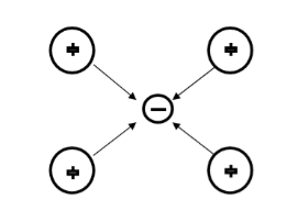
Figure 12: Electron-Positive Ion Interaction
The second electron interacts with the first electron due to the exchange of virtual photon q, between two electrons. The interaction process can be written in terms of the wave vector k as
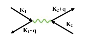
Figure 13: Interaction Process
k1’ =k1–q k2’ = k2+q
These two electrons together form a cooper pair and are known as cooper electrons.
Cooper pairs
To understand the mechanism of cooper pair formation, let us consider the distribution of electrons in metals as given by the Fermi-Dirac distribution function.
F(E) = 1/ 1+ e E-EF/kT
At T= 0K, all the Fermi energy states below the Fermi level are filled and all the states above are empty. Let us see what happens when two electrons are added to metal at absolute zero. Since all the quantum states E<EF, are filled, they are forced to occupy states having E>EF.
Cooper showed that if there an attraction between the two electrons, they can form a bound state so that their total energy is less than 2EF. These two electrons are paired to form a single system. These two electrons form a cooper pair and are known as cooper electrons.
Coherence length
The paired electrons are not scattered and can maintain their coupled motion up to a certain distance called the coherence length. It is a measure of the distance within which the gap parameter does not change very much in a varying magnetic field.
Key Takeaways
- BCS theory showed that the basic interaction responsible for superconductivity appears to be that of a pair of electrons by means of an interchange of virtual phonons.
- Cooper showed that if there an attraction between the two electrons, they can form a bound state so that their total energy is less than 2EF.
- These two electrons are paired to form a single system. These two electrons form a cooper pair and are known as cooper electrons.
- The paired electrons are not scattered and can maintain their coupled motion up to a certain distance called the coherence length.
The high-Tc superconductors are the class of materials with the highest recorded transition temperatures, on the order of 100 K and above. Discovered over 20 years ago, there remain a number of unanswered questions about these compounds.
The first high temperature superconductor was discovered in 1986, by IBM researchers Bednorz and Müller,who were awarded the Nobel Prize in Physics in 1987 "for their important break-through in the discovery of superconductivity in ceramic materials".
High-temperature superconductors (abbreviated high-Tc or HTS) are operatively defined as materials that behave as superconductors at temperatures above 77 K (−196.2 °C; −321.1 °F), the boiling point of liquid nitrogen, one of the simplest coolants in cryogenics. All superconducting materials known at ordinary pressures currently work far below ambient temperatures and therefore require cooling. The majority of high-temperature superconductors are ceramic materials. On the other hand, Metallic superconductors usually work below -200 °C: they are then called low-temperature superconductors. Metallic superconductors are also ordinary superconductors, since they were discovered and used before the high-temperature ones.
Ceramic superconductors are now becoming suitable for some practical use, but they still have many manufacturing issues and there are very few successful practical examples of employment. Most ceramics are brittle which makes the fabrication of wires from them very problematic.
The major advantage of high-temperature ceramic superconductors is that they can be cooled by using liquid nitrogen. On the other hand, metallic superconductors usually require more difficult coolants - mostly liquid helium. Unfortunately, none of high-temperature superconductors are cool able using only dry ice, and none of them works at room temperature and pressure (they work well below the lowest temperature recorded on Earth). All high-temperature superconductors require some kind of cooling systems.
The main class of high-temperature superconductors are in the class of copper oxides (only some particular copper oxides). The second class of high-temperature superconductors in the practical classification is the class of iron-based compounds. Magnesium diboride is sometimes included in high-temperature superconductors: it is relatively simple to manufacture, but it super conducts only below −230 °C, which makes it unsuitable for liquid nitrogen cooling (approximately 30 °C below nitrogen triple point temperature). For example, it can be cooled with liquid helium, which works at much lower temperatures.
Many ceramic superconductors physically behave as superconductors of the second type.
Some extremely-high pressure superhydride compounds are usually categorized as high-temperature superconductors. In fact, many articles on high-temperature superconductors can be found on this research on high pressure gases, which is not suitable for practical applications. The current TC record holder is lanthanum decahydride.
One of the key mysteries surrounds the identity of the so-called 'pseudo gap' region of the phase diagram. In this regime there exists a gap like feature observed in many physical quantities, yet there is no obvious signs of an ordered phase. Some of the research in the group has been directed at studying the specific heat of the high-Tc's in the pseudogap region of the phase diagram.
A second intriguing question surrounds how the high-Tc's evolve with charge carrier concentration (doping), moving from an antiferromagnetically ordered insulator at low doping, to an unconventional superconductor and eventually a Fermi liquid metal at higher doping. At low dopings, there is evidence for a 'glassy' behaviour of electronic spins, and part of the research effort is directed towards exploring this region of the phase diagram through muon-spin relaxation, transport and dielectric measurements.
Key Takeaways
- The high-Tc superconductors are the class of materials with the highest recorded transition temperatures, on the order of 100 K and above.
- The first high temperature superconductor was discovered in 1986.
- The major advantage of high-temperature ceramic superconductors is that they can be cooled by using liquid nitrogen.
- Superconductors form the basis of energy-saving power systems, namely the superconducting generators, which are smaller in size and weight, in comparison with conventional generators.
- Superconducting magnetic propulsion systems may be used to launch satellites into orbits directly from the earth without the use of rockets.
- High-efficiency ore-separating machines may be built using superconducting magnets which can be used to separate tumour cells from healthy cells by the high gradient magnetic separation method.
- Since the current in a superconducting wire can flow without any change in magnitude, it can be used for transmission lines.
- Superconductors can be used as memory or storage elements in computers.
- If you set up a current in a loop of superconductor there is nothing to stop it and it will continue flowing forever, forming a very powerful electromagnet, that needs no maintenance other than keeping them cold. The strongest man-made permanent magnetic fields are produced using superconductors.
- Superconducting magnets are used in MRI (Magnetic Resonance Imaging) which is a way of looking at the soft parts of the body.
- They are also going to be used in the new ‘Large Hadron Collider’ experiment at the CERN Particle Physics Lab. The idea is to accelerate protons and antiprotons to almost the speed of light in a circle and then smash them together. To keep the particles in a circle requires huge magnetic fields which can only be provided by superconductors.
- It is also possible to use superconducting magnets to produce a levitating train. The idea is to put very powerful light superconducting magnets on the train, then use copper coils in the track which use repulsion to lift the train to make it levitate. It is also possible to use the track magnets to push the train along. Because this force is not limited by friction between wheels and a track it is theoretically possible for a maglev train to go much faster and more importantly accelerate and brake faster than a conventional train. Various test maglev trains have been built, in Birmingham, Japan, and Germany, although the only one used commercially is a german design built-in Shanghai, which uses very strong permanent magnets instead of superconductors.
- Due to the subtlety of the quantum mechanics of how superconductors interact with magnetic fields, it is possible to make the most sensitive magnetometers possible called SQUIDs (Superconducting Quantum Interference Devices). These can be used to detect submarines, measure the magnetic field produced by your brain, find ore deposits deep underground, sense minute signals from stars, etc.
- An obvious use of superconductors would be to move power around, huge amounts of electrical energy are wasted just heating power cables, and superconductors would help. However, if you put alternating current through them they are no longer lossless, and it requires a lot of energy to cool them, so although it is possible they could be used to save energy in the long run in the short term it is more likely they will be used to save space, superconducting cables have been installed in Chicago and Copenhagen, in old cable ducts with restricted space, allowing you to get more power through the same duct, hence saving lots of money digging up the road. Similarly, the US Navy is very interested in them making small powerful electric motors to power ships with, because it is efficient to put the propellers on pods under the ship however the bigger the motor the more drag it produces, so a much smaller superconducting motor would be advantageous.
Reference
I. Engineering physics- Gaur and Gupta, & S.Chand Publication
2. Engineering physics - Avadhanalu and Kshirsagar, S.Chand Publication
3. Introduction to Solid State Physics -- Charles Kittel
4. Solid State Physics -- S.O.Pillai