UNIT 3
TRANSFORMERS AND 3-PHASE INDUCTION MOTORS
3.1.1 Electromagnetic induction
Electromagnetic Induction is the process of using magnetic fields to produce voltage, and in a closed circuit, a current.
3.1.2 Faradays laws statically induced EMF
Michael Faraday’s famous law of electromagnetic induction states: “that a voltage is induced in a circuit whenever relative motion exists between a conductor and a magnetic field and that the magnitude of this voltage is proportional to the rate of change of the flux”.
So how much voltage (emf) can be induced into the coil using just magnetism is determined by the following 3 different factors.
- 1). Increasing the number of turns of wire in the coil – By increasing the amount of individual conductors cutting through the magnetic field, the amount of induced emf produced will be the sum of all the individual loops of the coil, so if there are 20 turns in the coil there will be 20 times more induced emf than in one piece of wire.
- 2). Increasing the speed of the relative motion between the coil and the magnet – If the same coil of wire passed through the same magnetic field but its speed or velocity is increased, the wire will cut the lines of flux at a faster rate so more induced emf would be produced.
- 3). Increasing the strength of the magnetic field – If the same coil of wire is moved at the same speed through a stronger magnetic field, there will be more emf produced because there are more lines of force to cut.
Simple Generator using Magnetic Induction
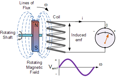
The simple dynamo type generator above consists of a permanent magnet which rotates around a central shaft with a coil of wire placed next to this rotating magnetic field. As the magnet spins, the magnetic field around the top and bottom of the coil constantly changes between a north and a south pole. This rotational movement of the magnetic field results in an alternating emf being induced into the coil as defined by Faraday’s law of electromagnetic induction.
The magnitude of the electromagnetic induction is directly proportional to the flux density, β the number of loops giving a total length of the conductor, l in meters and the rate or velocity, ν at which the magnetic field changes within the conductor in meters/second or m/s, giving by the motional emf expression:
Faraday’s Motional emf Expression

If the conductor does not move at right angles (90°) to the magnetic field then the angle θ° will be added to the above expression giving a reduced output as the angle increases:

3.1.3 Lenz law
Lenz’s Law states that:” the direction of an induced emf is such that it will always opposes the change that is causing it”. In other words, an induced current will always OPPOSE the motion or change which started the induced current in the first place and this idea is found in the analysis of Inductance.
Likewise, if the magnetic flux is decreased then the induced emf will oppose this decrease by generating and induced magnetic flux that adds to the original flux.
Lenz’s law is one of the basic laws in electromagnetic induction for determining the direction of flow of induced currents and is related to the law of conservation of energy.
According to the law of conservation of energy which states that the total amount of energy in the universe will always remain constant as energy cannot be created nor destroyed. Lenz’s law is derived from Michael Faraday’s law of induction.
One final comment about Lenz’s Law regarding electromagnetic induction. We now know that when a relative motion exists between a conductor and a magnetic field, an emf is induced within the conductor.
But the conductor may not actually be part of the coils electrical circuit, but may be the coils iron core or some other metallic part of the system, for example, a transformer. The induced emf within this metallic part of the system causes a circulating current to flow around it and this type of core current is known as an Eddy Current.
3.1.4 BH characteristics
The rms voltage induced in a transformer is given by E = 4.44φmfN ---------(1)
Where, φm is maximum value of the flux in the core, f is operating frequency and N is number of turns in the coil.
This flux in the coil is given by φm = BmAc ----------(2)
Where, Bm is the maximum flux density in core and Ac is the cross-sectional area of the core.
So, we have E = 4.44BmAcfN -----------------(3)
The value of induced voltage E is thus dependent upon Bm which can be setup in the core.
From Biot-Savart’s law that a current carrying conductor produces magnetic field.
“Magnetic field strength” H is proportional to the current which produces the field.
From Ampere’s Circuital law, it can be proved that H is proportional to current I.
If a current carrying coil produces magnetic flux which traverses an average length of l in complete flux path, then
Hl = NI -------------------------------(4)
In a magnetic circuit, this field is represented by magnetomotive force. It is analogous to the electromotive force in electrical circuit. This field is responsible to “set up” certain flux, which in turn gives rise to certain flux density B.
The amount of flux which can be setup in a material is determined by an inherent property of the material, called as permeability, denoted by
µ. B = µH --------------------------------(5)
Let us consider materials used in the laminations of transformers. They are called ferromagnetic materials. A piece of ferromagnetic material is composed of several “domains”. In each domain, magnetic moments of all atoms are aligned in one direction. In general, the domains are randomly oriented.
When external magnetic field H is applied to a material, all the domains align in a particular direction, setting up “net flux” in the material. Due to domain alignment B (i.e. the magnitude of B) increases. However, after a certain value of B, the slope of B − H curve starts reducing as shown in Fig. 1;
O − S1 represents the linear region and
S1 − S2 represents the “saturation region”.

From Faraday’s law,
V = N dφ /dt
B is directly proportional to flux φ. A signal proportional to B can be obtained by integrating the voltage signal. The voltage can be integrated approximately by using an RC circuit.
The transfer function of the circuit is given by

The time constant τ = RC should be chosen such that, in frequency domain (1 + jωτ ) ≈ jωτ
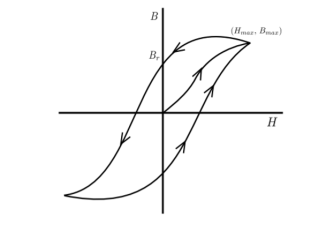
Hysteresis loop
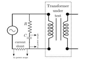
Equation 4 tells that H is is proportional to current. The two signals can be given to two channels of a digital storage oscilloscope. B − H curve of the material can be seen.
3.1.5 Ideal and practical transformer
An ideal transformer is one that has
- No winding resistance
- No leakage flux i.e., the same flux links both the windings
- No iron losses (i.e., eddy current and hysteresis losses) in the core
Although an ideal transformer cannot be physically realized, yet its study provides a very powerful tool in the analysis of a practical transformer. In fact, practical transformers have properties that approach very close to an ideal transformer.
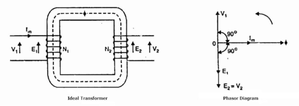
Consider an ideal transformer on no load i.e., the secondary is open-circuited as shown in the figure. Under such conditions, the primary is simply a coil of pure inductance.
When an alternating voltage V₁ is applied to the primary, it draws a small magnetizing current Iₘ which lags behind the applied voltage by 90°. This alternating current Iₘ produces an alternating flux ϕ which is proportional to and in phase with it.
The alternating flux ϕ links both the windings and induces e.m.f. E₁ in the primary and e.m.f. E₂ in the secondary. The primary e.m.f. E₁ is, at every instant, equal to and in opposition to V₁ (Lenz’s law). Both e.m.f.s E₁, and E₂ lag behind flux ϕ by 90°. However, their magnitudes depend upon the number of primary and secondary turns.
Phasor Diagram of Ideal Transformer
The phasor diagram of an ideal transformer on no load is also shown above. Since flux ϕ is common to both the windings, it has been taken as the reference phasor.
The primary e.m.f. E₁ and secondary e.m.f. E₂ lag behind the flux ϕ by 90°.
Note that E₁ and E₂ are in phase. But E₁ is equal to V₁ and 180° out of phase with it.
Practical Transformer
A practical transformer differs from the ideal transformer in many respects. The practical transformer has,
- Iron losses,
- Winding resistances and,
- Magnetic leakage, giving rise to leakage reactance.
1. Iron Losses
Since the iron core is subjected to alternating flux, there occurs eddy current and hysteresis loss in it. These two losses together are known as iron losses or core losses.
The iron losses depend upon the supply frequency, the maximum flux density in the core, volume of the core, etc.
It may be noted that the magnitude of iron losses is quite small in a practical transformer.
2. Winding resistances
Since the windings consist of copper conductors, it immediately follows that both primary and secondary will have winding resistance. The primary resistance R₁ and secondary resistance R₂ act in series with the respective windings as shown in the figure.
When current flows through the windings, there will be power loss as well as a loss in voltage due to IR drop. This will affect the power factor and E₁ will be less than V₁ while V₂ will be less than E₂.

3. Leakage reactances
Both primary and secondary currents produce flux. The flux ϕ which links both the windings is the useful flux and is called mutual flux.
However, the primary current would produce some flux ϕ which would not link the secondary winding. Similarly, the secondary current would produce some flux ϕ that would not link the primary winding.
The flux such as ϕ₁ or ϕ₂ which links only one winding is called leakage flux. The leakage flux paths are mainly through the air. The effect of these leakage fluxes would be the same as though inductive reactance were connected in series with each winding of the transformer that had no leakage flux as shown in the figure.
In other words, the effect of primary leakage flux ϕ₁ is to introduce an inductive reactance X₁ in series with the primary winding as shown. Similarly, the secondary leakage flux ϕ₂ introduces an inductive reactance X₂ in series with the secondary winding.
There will be no power loss due to leakage reactance. However, the presence of leakage reactance in the windings changes the power factor as well as there is voltage loss due to IX drop.

Note.
Although leakage flux in a transformer is quite small (about 5% of ϕ) compared to the mutual flux ϕ, yet it cannot be ignored.
It is because leakage flux paths are through the air of high reluctance and hence require considerable e.m.f. It may be noted that energy is conveyed from the primary winding to the secondary winding by mutual flux f which links both the windings.
3.1.6 Losses and efficiency
- Losses in a Transformer
There are 2 types of losses occurring in a transformer
A) 1. Core loss or Iron loss
B) 2. Copper loss
- Core losses:
- This loss is due to the reversal of flux
- The flux set up in the core is dependent on the i/p supply
 as the i/p supply is constant in magnitude
  the flux set up will be constant and
  core losses are also constant.
 - Core losses are voltage dependent loss they can be subdivided in 2
1 Hysteresis loss
2 reedy current loss
- Hysteresis loss : The iron loss occurring in the core of T/F due to the Hysteresis curve of the magnetic material used for core is called as Hysteresis loss.
Hysteresis curve is the curve as loop which shows the properly of magnetic material to lag the flux density B behind the field Intensely H
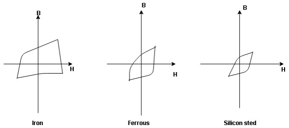
Above is the 3 different loops (Hysteresis of 3 diff. Materials)
 the selection of magnetic material for the construction of core depends upon Hysteresis loop of that material having tall and narrow Hysteresis loop is selected for the T/F core
 silicon Steel
Hysteresis loss depends on fold factor
PH = KH. Bm1.67 F  V – watts
Where KH = constant (Hyst)
Bm = max Flux density
F = Frequency
 = Volume of core.
2. Reedy current loss :
This loss is due to the flow of reedy (circular) current in the core caused by induced emf in core
PE = Ke Bm2 f2 t2 v – watts
Where
Ke = reedy current const.
t = thickness of core
It can be reduced by using stacks of laminations instead of solid core
B] Copper loss : PCU
The Copper loss is due to resistance of the primary and secondary winding
It is load dependent / current dependent loss
As load on a transformer is variable (changing)  current changes
  copper loss is a variable loss
Primary secondary
Total C is loss = I12R12 + I22 R22
Copper loss depends upon load on T/F and is proportional to square of load current or KVA rating of transformer
 PCU
PCU  2
2 (KVA)2
F.L = full load
 PCU (at half load) =
  2 PCu F.L
= (0.5)2 PCU F.L.
Or PCu ( load) = (
 )2 PCu F.L
Efficiency : it is the ratio output power to input power of transformer
 =
= 
Output power = input power – total loss
 Input power = O/P + losses

O/P power = KVA  Cos Ø2
  1000
1000
Or = V2  I2 Cos Ø2
Losses = Pi + PCU (F.L)
= iron + copper loss
 Full load =
 Half load(H.L) or 50% or 0.5 =

 =
= 
Maximum efficiency – for numerical :
The efficiency of T/F is maximum when copper loss equates iron loss this is the condition for max efficiency
Ie Pi = PCU
 =
= 
 PCU = Pi at max n
Where KVA at max n given = Full load KVA 
3.1.7 Auto-transformer and three-phase transformer connections
Auto Transformer
An auto Transformer is a special type of transformer such that a part of the winding is common to both primary as well as secondary
It has only One winding wended on a laminated magnetic core
With the help of auto Transformer, the voltage can be stepped up and stepped down at any desired value
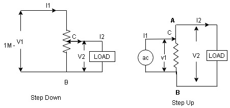
Fig A shows auto T/F as step down T/F variable terminal B C is connected to load and it acts as secondary wdg.
The position of point C is called as topping point can be selected as per requirement
Fig. B show auto T/F as step up T/F variable terminal B C is connected to supply side i.e. ac side and it acts as secondary winding
The operating principle of auto Transformer is same as that of 2 winding Transformer
Advantages
- Weight of copper required in an auto Transformer is always loss than that of the conventional 2 winding Transformer and hence it is cheaper.
- Compact in size and loss costly.
- Losses taking place in Transformer is reduced hence efficiency is higher than conventional Transformer.
- Due to reduced resistance, voltage, regulation is better than conventional T/F.
Disadvantages:
As low voltage and high voltage sides are not separate then there is always risk of electric shocks when use for high vtg. Applications
Applications
- Starting squirrel cage induction motor and synchronous motor.
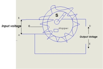
- Auto transformer as dimmer stat
- Used as variable ac to variable ac Voltage
3.2.1 Generation of rotating magnetic fields
The stator of an induction motor consists of a number of overlapping windings offset by an electrical angle of 120°. When the primary winding or stator is connected to a three-phase alternating current supply, it establishes a rotating magnetic field which rotates at a synchronous speed.
The waveform of the three fluxes is as given below.
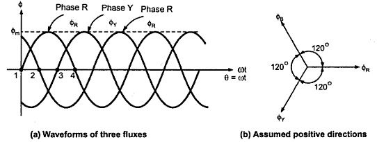
The three-phase winding carry the balance current if the applied sinusoidal voltage is balanced and the impedance of each winding is also balanced. The stator winding is physically placed 120 electrical degree apart.
If the phase sequence is R,Y,B, the Y phase current lags the R phase current by 120 degree and B phase current lags the Y phase current by 120 degree or leads the R phase current by 120 degree. The phase current Ir, Iy and Ib set up flux in the core. The resultant magnitude of the average flux can be calculated by adding the magnetic flux produced by individual current.
Let us first take the case when the R phase current at zero position of the waveform. The flux produced by the R phase current is Фr.
Фr = Фm sin(o) = 0
Фy = Фm sin(0-120) =Фm sin(-120) = - 0.866 Фm
Фb = Фm sin(0-240) =Фm sin(-240) = 0.866 Фm
If we add the instantaneous value of the fluxes produced by phase voltages, the resultant flux in the motor
Average flux= 1.5 * Maximum Flux
The average flux of constant magnitude rotates in the same way as the input three supply phases rotate.
3.2.2 Construction and working of a three-phase induction motor
Consider- 3Ф slip ring I.M
Cut section diagram: -
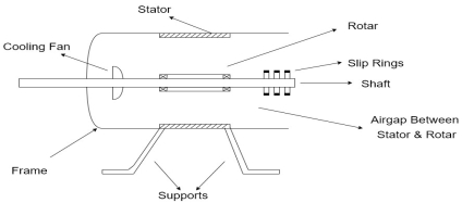
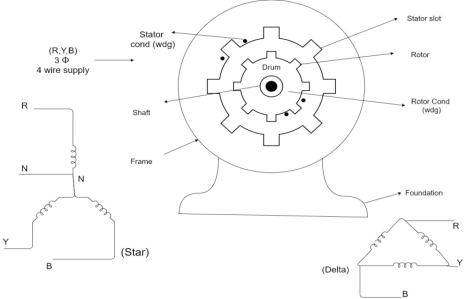
The induction motor has following important parts:-
- Stator :- it is the stationary part of induction motor and it is one of important part in induction motor.
- Rotor:- the rotor is the rotating part of induction motor which consists of rotor wdg.
- Stator winding:- this wdg. Is mounted on devastator and it generates the RMF i.e. rotating magnetic field.
- Rotor winding:- rotor winding is used to rotate the shaft of motor. This wdg is provided on rotor
- Frame :- it provides the mechanical support to the motor. It is the outer covering of motor. It protects the internal parts of motor from damage.
- Shaft:- shaft is used to connect to the load and four rotation.
- Slip rings and brushes:- slip rings are mounted on the shaft which is connected with brushes from which connection is given to the external resistant or rheostat
- Cooling fan:- this is provided for cooling purpose of motor and its internal parts.
Principle of operation of induction motor:
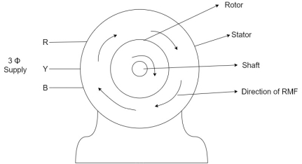
- When the 3Ф A.C supply is connected across the stator of induction motor, the current starts flowing through the stator wdg. i.e the stator condition.
- Due to this current of flux (Ф) is established in the stator wdg. This flux (Ф) is alternating (changing) in nature. Thus this flux links with the rotor also, and a a Rotating Magnetic Field (RMF) is produced.
- This flux (Ф) induces in the rotor also. The RMF is produced in the air gap between stator and rotor.
- The rotor is rotating part which is till stationary, show the rotating magnetic field is cut by stationary rotor and an EMF is induced in the rotor winding. According to faraday's law of EMI the rotor EMF gives the rise to rotor current which opposes the main cause producing it according Lenz's law.
3.2.3 Squirrel cage IM, slip-ring IM
Types of induction motor:
Two main types depending upon the rotor
- Squirrel cage induction motor (squirrel cage rotor)
- Slip ring induction motor(slip ring or wound rotor)
Induction motor are also available in 1Ф supply i.e.
1. Resistance split phase induction motor
2. Capacitor start induction motor
3. Capacitor start capacitor run induction motor
4. 1Ф induction motor i.e. A.C series motors
5. Shaded pole induction motor
Torque equation of induction motor:-
Torque produced in induction motor depends upon the following factors
1.The rotor power factors ( CosФ) under running condition
2.The rotor current under running condition
3. The part of RMF which induces EMF in rotor wdgi.e. flux (Ф)
We can mathematically say that,
 , As per DC (M) equation
But in case of induction motor
Suffix 1 -> used for stator/stator parts (qty)
Suffix 2-> used for rotor/rotor parts(qty)
Therefore,  ----(1)
 = flux that induces the EMF in rotor
 = rotor current under running condition
 = P.F of rotor
But, stator vtg
 also i.e
 ----(2)
Transformation ratio i.e. given by 
Therefore,
 and hence
 also
also
 at slip ’S’ is given by
And also  at slip ‘S’ is
  =S.
=S.
Hence  in equation can be replaced by
i.e.  U
U
 =
= ----(3)----(
 )
)
4 =
= ------(4)
Subtract (3) and (4) into (1) equation we get,


 (N-m) , Torque equation of I.M.


At starting condition slip S=1
So, 
3.2.4 Applications
There are a lot of applications of 3 phase induction motor, to name a few
1). Electric Train engine
2). Cooling fans used to cool large machines like alternators etc
3). Chimneys at power plants
4). Printing machines
5). Rolling mills