Unit - 2
FEM Procedure
- The finite element method (FEM) is the most widely used method for solving problems of engineering and mathematical models.
- Typical problem areas of interest include the traditional fields of structural analysis, heat transfer, fluid flow, mass transport, and electromagnetic potential.
- The finite element method is a numerical procedure for obtaining solutions to boundary-value problems. The principle of the method is to replace an entire continuous domain by a number of subdomains in which the unknown function is represented by simple interpolation functions with unknown coefficients.
- Thus, the original boundary-value problem with an infinite number of degrees of freedom is converted into a problem with a finite number of degrees of freedom, or in other words, the solution of the whole system is approximated by a finite number of unknown coefficients.
- Therefore, a finite element analysis of a boundary-value problem should include the following basic steps:-
- Discretization or subdivision of the domain
- Selection of the interpolation functions (to provide an approximation of the unknown solution within an element)
- Formulation of the system of equations (also the major step in FEM. The typical Ritz variational and Galerkin methods can be used.)
- Solution of the system of equations (Once we have solved the system of equations, we can then compute the desired parameters and display the result in form of curves, plots, or color pictures, which are more meaningful and interpretable.)
- The first step and the last step are most relevant with the visualization process. These 2 steps are described in greater detail below.
Domain Discretization
- The discretization of the domain is the first and perhaps the most important step in any finite element analysis because the manner in which the domain is discretized will affect the computer storage requirements, the computation time, and the accuracy of the numerical results. The subdomains are usually referred to as the elements.
- For a 1D domain which is actually a straight of curved line, the elements are often short line segments interconnected to form the original line [Fig2 (a)]. For a 2D domain, the elements are usually small triangles and rectangles [Fig2 (b)].
- The rectangular elements are, of course, best suited for discretizing rectangular regions, while the triangular ones can be used for irregular regions. In a 3D solution, the domain may be subdivided into tetrahedral, triangular prisms, or rectangular bricks [Fig2(c)], among which the tetrahedral are the simplest and best suited for arbitrary-volume domains.
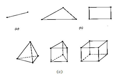
Fig.-1 Basic finite elements. (a) 1D (b) 2D (c) 3D
- Note that the linear line segments, triangles, and tetrahedral are the basic one-, two-, and three-dimensional elements. Figure3 shows the finite element discretization of a 2- and 3- dimensional domain.
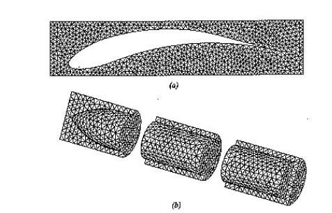
Fig.2 - Examples of finite element discretization
(a) 2-D with triangular elements
(b) 3-D with tetrahedral elements
Solution of the system of equations-
- Once we have solved the system of equations, we can then compute the desired parameters and display the result in form of curves, plots, or color pictures, which are more meaningful and interpretable. This final stage, often referred to as post-processing, can also be separated completely from the other steps.
Variational method- principles

U is solution to continum problem
F,E are differential operators
 is variational integral
Now, u is exact solutions if for any arbitary

i.e if variational integral is made “stationary”
Now the approximate solution can be found by substituting trial function expansion .


Since above holds true for any 
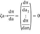
Parameter  are thus found from above eqn.
Note:
The presence of summetric coeffecient matrics for baove eqn. Is one of the primary merits to this approch
Natural and contrived – variational principles
Natural:
- Variational forms which aries from physical aspects of problem itself.
- Eg- mimnimum potential energy- equilibrium mechanical system .
Contrived-
- Lagrance multipliers:-extending number of unknown by addition of variable.
- Least square problems- procedures imposiong higher degree of continuity requirment.
- The shape function is the function which interpolates the solution between the discrete values obtained at the mesh nodes. Therefore, appropriate functions have to be used and, as already mentioned, low order polynomials are typically chosen as shape functions. In this work linear shape functions are used.
- In FEM analysis, the displacement model be assume the variation of displacement within the element since the two variation of displacement are not known.
- But in higher engineering mathematics analytical solution of some problem is either not known or difficult to find out. In such cases we replaced that function by another function which is easy to solve mathematically that function is called as Shape function or Interpolation Function.
- Notes-
- The magnitude of shape function at each node is unity.
- Number of shape function is equal to number of nodes.
- The sum of shape function is always unity.
- Methods of deriving shape functions-
- Shape function using polynomials in Cartesian coordinate system.
- Shape function using polynomials in natural coordinate system.
- Shape function using Lagrange interpolation function in natural coordinate system.
1. Shape function for two noded bar elemnent in (x,y) co-ordinates :- let consider two noded bar element of length L.  are the certesian co-ordinaters of nodes 1&2 respectively .
  are displacement of nodes 1and 2 u is the displacement of any point in x-directions
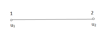
Fig.3
Total DOF =O2 (one 2t each node)
- Displacement function:-
u=λ1+λ2x
In matrix form


Where [p] =parametric matrix
II. Displacement function in-terms of nodal displacement: express displacement function in terms of nodal displacement using the coordinates of nodes 


Where [A] =connectivity matrix
Obtained  from Eq. (2) and put into eq(1) we get


Where [N] =shape functions
[N] =[p] 
III. Shape functions =

Inverse is obtained by using method of adjoin


Sum of shape functions is always unity

At node 1 x=

At node 2, x=

- The integral forms are most useful when dealing with macroscopic problems with high degrees of symmetry (e.g. Spherical or axial symmetry; or, following on from comments below, a line/surface integrals where the field is either parallel or perpendicular to the line/surface element)
- Just as definite integrals can be used to find the area under a curve, they can also be used to find the area between two curves.
- To find the area between two curves defined by functions, integrate the difference of the functions.
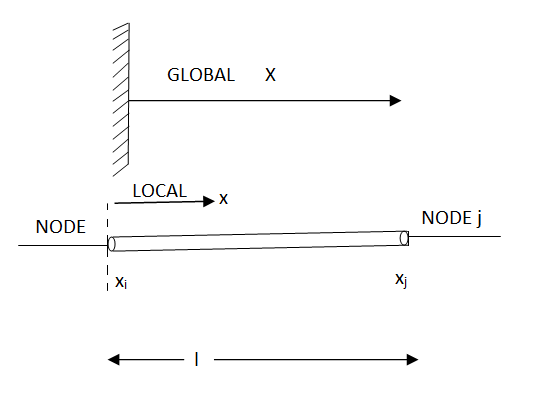
Fig.4
The relationship between a global coordinates X & a loacal coordinates x.

Linear shape functions in local ordinates


2. 


Notice 


Interpolation function | In term of global coordinates (x).  | In terms of local coordinates (x)  |
Linear |   |   |
Quadratic |    |    |
Cubic |     |     |
Natural coordinates in 1-D
- Natural coordinates are basically local coordinates in a dimensionless farm.
- Natural coordinates simplify numerical integration.
- Rotation is
 lower case
- The objective is for
 to be 1 at I & 1 at j .

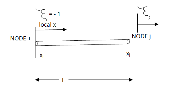
Fig.5
The relationship between local coordinates x& the natural coordinates 


Linear share function in natural coordinates


- The weighted residual method is employed to obtain approximate solutions to linear and nonlinear mostly non- structural problems whose characteristics are expressed in terms of differential equations.
- In weighted residual method, efforts have been taken to minimize the error by some kinds of procedure. Based on the methods of minimizing the error from approximate solution, the weighted residual technique can be adopted I four methods such as-
- Point collocation method
- Sub-domain method
- Least square method
- Galerkin’s method
- In Practice, the weighted residual methods are mostly preferred for non-structural problems whereas for structural problems Rayleigh-ritz method is adopted.

Point collocation method-
- The residual R(x ,ai) is set equal to zero at n specific points X1,X2,X3…….Xn.
- The weighted function can be expressed as
 in this method.

Sub-domain method
- In this method, the domain is subdivided into n sub-domains and the integral of the residual over each sub –domain is then required to be zero.
- That is, the weighted residual function is selected as unity (Wi=1) over the domain (i.e., some specific region).

Least square method-
- In this method, the integral of the weighted square of the residual over the domain is required to be a minimum.


Galerkin's method-
- In this method, the trial function y(x) itself is considered as the weighting function. The domain integral of the product of trial function with the residual is then set equal to zero.

Example:-
Given a differential equation


Find y(0.2) by gaterkin’s method
Solution :-
Step 1 :- see the order of the equation given :- if ‘n’ then assume polynomial of order/degree “n+1”
Now, 

Step 2 – apply boundary conditions one by one
i.e y(0) =1


Rewrite the approximately solution is

 --------c
Step 3- find the reside given by the differential equations
i.e ,

 -----------d
 -----------e
The residue becomes
 substitute all value from c, d and e


Step 4 – the weighted integral from


Wi -> coefficient of Ci in y
i.e from equation C

Now, putting i=1 , we get


Similarly putting i=2 , we get

On solving


Solving 1 & 2

Therefore,


Cantilever beam problem by galerkin’s method
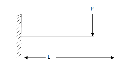
Fig. 6
Using galerkin’s method find the expression of a cantilever beam subjected to point load ‘p’ at the end having moment of inertia I . youngs modulus “E” & length of beam “L” .
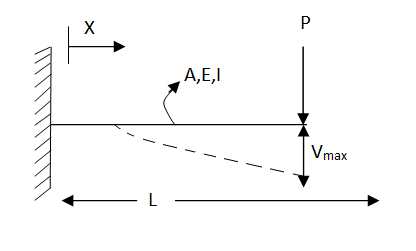
Fig.7
Step 1 – formulate differential equation of beam


Where v= disp. In ‘y’ dim
 =distributed load per unit length
 0
0
Step -3
Residual


Weighting function

Step -4
Use galerkin’s formulation 


Step – 5 find the unknown displacement

But 

The maximum disp. In beam at x=l


By using 4th boundary con


This is a admissible trial solution
Step – 2 trial balance function & boundary conditions

Boundary conditions

By 1st boundary conditions


By 3rd conditions


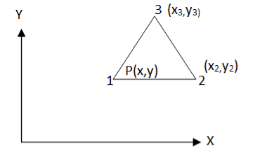
Fig.8
Let us consider three noded constant strain triangular (CST) element as shown in fig.  are the cartesian coordinate of nodes 1,2,3 respectively .
  are displacement of nodes 1,2,3 respectively. U,v are displacement of any point on the element having cartesian coordinates (x,y)
- Displacement function
In matrix form


Where [p]=parametric matrix
2. Displacement function in terms of nodal displacement express displacement function in terms of nodal displacement function in terms of nodal displacement using co-ordinates of nodal 


Where [A] = connectively matrix
Obtained  from eq. 2 and put into Eq. 1 we get


Where [N]= shape function .
3. shape functions
Considering displacement in x-direction only (i.e u same shape function sare applicable to displacement in y -direction i.e V )


Where


Let consider four noded rectangular element in cartesian co-ordinates system  are cartesian coordinates of nodes 1,2,3,4 respectively .
 are displacemnt of nodes 1,2,3,4 respectively u,v are displacment of any point on element having cartesian co-ordinates (x,y)
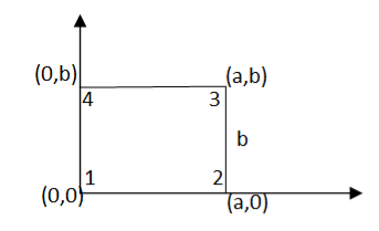
Fig.9
DoF 2 at each node
Total DoF : 08 (04 in x-direction and 04 in y-direction)
- Displacemnt function


Where [P] = parametric matrix
2. dispalcemnt function in terms of nodal displacemnt
Express displacement function in terms of nodal displacemnt using the co-ordinates of nodes (0,0) (a,0) (a,b) (0,b)

Where [A]= connectively matrix
Obtained  from eq . 2 and put into the equation 1 we get ,

Where [N]=shape function
3. shape function

Inverse is obtained using elementary operations of matrix algebra
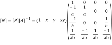


For 8 noded quadratic element .
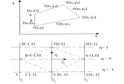
Fig.10


At node 1 ,


At node 2 , 
1= (1+1)(1+1)(-1+1+1)
1= (2) (2) (1)


At node 3 ,  =1 ,
=1 , 


At node 7 ,  =1 ,
=1 ,  =0 & n=1


At node 8,  ,
,  =-1 ,n=0


At node 4, 


At node 5 = 


At node 6, 


References-
(1) Finite element method with application in engineering by Chandrupatla & Belegundu, Pearson Publication.
(2) Finite Element Method Basics concept & Applications by Alawala
(3) Fundamental of Finite element Analysis by Devid V. Hutton
(4) Finite element Methods is fundamentals an application in engineering by Chen Z


