Unit - 5
Dams
- Definition: A solid barrier constructed at narrow outlet in a valley is called as dam.
- These are impervious in nature and are constructed to obstruct the flow of water. Thus, increases raising of water on upstream side.
Site selection for dams:
- The following points should be considered while selecting site for dam:
- Good foundation should be available.
- It should be located in a narrow valley.
- It should have sufficient space for spillway.
- It should have impervious bed and sides so as to reduce erosion.
- It should fulfil the purpose i.e., irrigation, drinking etc.
- Materials should be easily available nearby site.
- It should have less submergence area i.e., not more than 10 %.
- The site should be such that the length of dam should be minimum as it directly affect cost.
- It should be easily accessible throughout the year.
Factors affecting the selection of the type of dam:
- The factors which affect selection of dams are as follows:
- Material available.
- Funds available.
- Nature of foundation.
- Space for surplus work (i.e. spillways).
- Nature of valley.
- Seepage and uplift under dam.
Key Takeaways:
A solid barrier constructed at narrow outlet in a valley is called as dam.
- Various types of dams are classified according their purpose, materials, size, hydraulic design and structure action.
1. Classification of dam based on Purpose
- Storage dams
- Coffer dams
- Debris dams
- Diversion dams
- Detention dams
- Dams are classified according to the purpose or function served. Following the various types of dams classified based on purpose.
Storage dams:
- These dams are constructed to store the water in rainy season and further it can be used in other season for various purpose like water supply, generation of hydropower, irrigation etc.
Coffer dams:
- Coffer dam is a temporary structure constructed in the river or lake so as to make the area on downstream side completely free from water such that it is possible to carry the construction work under reasonably dry condition.
Uses of Coffer Dam
- Coffer dams are temporarily constructed for the construction of projects like, bridge piers and abutments, dams or locks, etc.
- It provides safe environment to work.
- Material of coffer dam can be typically reused on other construction project.
- Steel sheet piles can be easily installed and removed.
Debris dams:
- These types of dams are being constructed to avoid the flow of debris such as sand, gravel. Drift wood along with rain water in the river and such way water becomes relatively clear and clean after passing over the debris dam.
Diversion dam:
- This type of dams is relatively having of low height. It is specially constructed so as to divert the water of the river into an off-taking canal or conduit.
Detention dams:
- These types of dams are being constructed in case of excessive flood and thus such dams control the floods.
2. Classification of dams based on Material
- Concrete dam
- Concrete gravity dam
- Concrete buttress dam
b. Masonry dam
c. Timber dam
d. Steel dam
e. Earth
f. Rock fill
g. Composite dam
Various dams are classified based on the materials used for their construction.
Following are the various types of dams based on materials.
Concrete dam:
- Material used for such dam is concrete.
- Gravity dams, arch dams and butters dams are classified as concrete dams.
Masonry dam:
- Materials used for such dam are stone rubbles, bricks etc.
Timber dam:
- Material used for such dam is wood.
Steel dam:
- Material used for such dam is steel.
Earth dam:
- Material used for such dam is clay or earth.
Rock fill dam:
- Material used for such dam is rock fill.
Composite dam:
- Material used for such dam is rock fill and earth fill.
- Earth dam as well as rock fill dam comes under the type of embankment dam.
Concrete dam:
- Concrete dam is basically classified into two types:
Concrete gravity dam:
- Concrete gravity dam is a rigid type of dam in which the external forces like water pressure, wave pressure, silt pressure, uplift pressure are resisted by the weight of the dam itself.
- All major and important gravity dams are constructed in concrete. Concrete gravity dam can be straight or curved in plan.
Concrete buttress dam:
- This type of dam consists of a number of pier or buttress dividing the space to be dammed into a number of spans.
- Panels are constructed of horizontal arches or flat slabs so as to hold up and retain the water between buttresses.
- Definition: If panels consist of concrete arches, then it is called as multiple arches buttress dam and it panels consists of flat slab, then it is called as deck type buttress dam.
3. Classification of dams based on Hydraulic Action
- Overflow dams
- Non-overflow dams
Overflow dams:
- Overflow dam in which surplus water is permitted to pass over the crest of the spillway.
Non-overflow dams:
- Non-overflow dam in which there is no flow of water over it. Such type of dam can be made of any material like concrete, earth, timber, rock fill, masonry etc.
4. Types of dams based on Structural action
These types of dams are classified into various types based on the structural action.
- Gravity dams
- Earth dams
- Rockfill dams
- Timber dam
- Rock-filled crib rock type
- A-frame type
- Beaver type
e. Steel dam
- Cantilever type steel da
- Direct strutted steel dam
Gravity dams:
- Definition: The dam due to its own weight resists the water pressure and other forces is called as gravity dam.
- It is made either in concrete or masonry.
Earth dams:
- Definition: The dam made in earth or soil resists the forces exerted upon it mainly because of shear strength of soil is called as earth dams
Rockfill dams:
- Definition: The dams made in rock fragments and large size boulders with an impervious membrane placed on the rock fill on its upstream side is called as rockfill dam.
- Impervious membrance reduces the seepage through the dam.
Timber dam:
- Definition: The dam which consists of the me work made in timber with a facing of timber planks is called as timber dam.
- Timer dam are classified into three types:
- Rock-filled crib rock type
- A-frame type
- Beaver type
Steel dam:
- Definition: The dam which consist of a steel framework with a steel skin plate on its upstream face is called as steel dam.
- Such dams are classified into the types
- Cantilever type steel dam
- Direct strutted steel dam
- Definition: The dams which are constructed of earthen materials such as gravel sand, silt and clay are called as earthen dam.
- It has trapezoidal section with a top width of 3 to 10 m and upstream slope of 1 V: (2.5 to 4) H downstream slopes of 1 V: (2 to 3) H.
Advantages and Limitation of an Earth Dam:
Advantages:
- Following are the advantages of earth dam
- The main advantage of such type of dam is such that it can be constructed on any type of foundation strata which contains soil, gravel, earth murum, rock etc.
- Such dams are suitable and favourable for the sites with very wide to steep valleys.
- Earth dam can be constructed with the use of locally available natural material and hence cost of transport becomes less.
- The design of such dam is flexible such that different types of material can be used for its construction.
- There is a continuous process of construction with highly mechanized system.
Limitations:
- Following are the various limitations of an earth dam:
- An earth dam requires a supplementary structure for spillway.
- There are more chances of susceptible leakage and erosion of the foundation.
- Insufficient capacity of spillway causes the failure of the dam structure because dam is likely to be over-tapped.
- Dam structure can be subjected to damage because of burrowing animals.
Key Takeaways:
Definition: The dams which are constructed of earthen materials such as gravel sand, silt and clay are called as earthen dam. It has trapezoidal section with a top width of 3 to 10 m and upstream slope of 1 V: (2.5 to 4) H downstream slopes of 1 V: (2 to 3) H.
- The various types of earthen dam are as follows:
1. The main types of earthen dam
- Homogeneous type embankment dam
- Diaphragam type earthen dam
- Zoned type embankment dam
2. Types of earth dams based on Methods of construction
- Rolled fill earth dam
- Hydraulic-fill earth dam
- Semi-hydraulic earth dam
- There are mainly three types of earthen dams:
- Types of earth dams based on methods of construction are as follows:
1. Homogeneous embankment type of dam
- It is one of the types of earthen dam which consist of earthen embankment of simple type and made in a single material hence it is homogeneous throughout.
- Fig. Shows homogeneous type embankment dam without any internal drainage system.
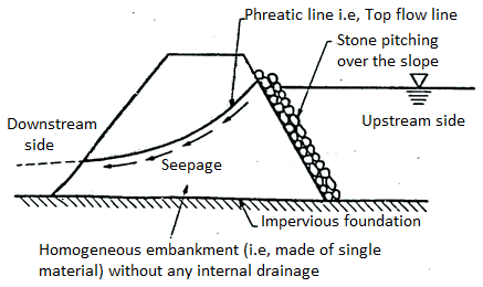
Fig 1: Homogenous type embankment of dam
- Fig. Shows homogeneous embankment type of dam with provision of a drainage filter.
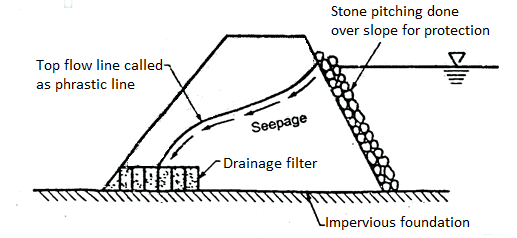
Fig 2: Homogenous embankment with a drainage filter system
- When only one type of material is locally available and which is economical, then a purely homogeneous section is used.
- This type of homogeneous section is used for low to moderately high dams and also for levees.
- A purely homogeneous section creates great problem of seepage and section has to make a big section or a huge section so as to make the whole structure more safe against piping, stability etc.
- Hence due to fact of piping and stability, a homogeneous section is built-up with an internal drainage system like a horizontal drainage filter as shown in Fig.; rock toe etc.
- Internal drainage system keeps the top seepage line (phreatic line) properly within the body of the dam. Hence internal drainage system is more useful and always provided nearly all types of embankments.
2.Diaphragm type of embankment dam
- This type of embankment dam consists of an impervious core called as diaphragm which is surrounded by earth or rock fill.
- Impervious core or diaphragm is made of impervious soils, timber, concrete, steel or any other suitable material. Diaphragm serves as a obstacles or water barrier so as to avoid the seepage through the dam.
- Diaphragm is located at the centre of the dam section or located or placed at the upstream face as a blanket. Diaphragm should be well connected to the bed rock or to a very impervious foundation material. Due to this connection between diaphragm and bed rock or impervious foundation, the possible excessive under seepage through the existing pervious foundation can be prevented.
- Fig. Shows a diaphragm type embankment.

Fig 3: Diaphragm type embankment dam
- Note that diaphragm type of embankment dam and zoned embankment dam are differentiated in point of view of their thickness of core. When thickness of the diaphragm type of embankment is le s than 10 m at any elevation or less than the height (h) of the embankment, then it is in the category of diaphragm type; but when the thickness becomes equal or more than the 10m, than it is in the type of zoned embankment.
3.Zoned type embankment dam
- This type of embankment consists of usually a central impervious core covered by a transition zone which is surrounded by a pervious outer zone.
- Fig. Shows the zoned embankment type of dam.
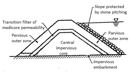
Fig 4: Zoned type embankment dam
- Central core is useful to check the seepage. The transition zone is advantageous for preventing the piping through cracks which may likely to set up in the central core. The outer zone provides stability to the central impervious fill and also distribute the load over the larger area of foundations.
- Clay is highly impervious, but sometimes it does not make the best core, if it expands and shrinks in large extent. Hence clay is sometimes mixed with fine gravel or fine sand so as to make the most suitable material for the central core sometimes silty clay or silts can be used as the central core materials.
- In outer shell, the coarse sand and gravels which acts as a freely draining material are used.
- In between, inner zone and outer zone, the transition filters are provided. When there is an abrupt change of permeability from one zone to another zone, then in such circumstances, transition filters are best suited and hence provided.
Classification of Earth Dam Based on Methods of Construction and Materials:
- Classification of earth dam based on methods of construction and materials are as follows:
- Rolled-fill earth dam
- Hydraulic-fill-earth dam
Rolled-fill earth dam
- In such type of earth dam, the embankment is constructed by placing suitable soil material in thin layers about 150 mm to 300 mm and these layers are further compacted with the help of rollers.
- The soil obtained from burrow pits are brought to the site and properly spread with bulldozers in layers which are further compacted by rollers of designed weights.
- For low embankments like levees or bunds, the ordinary road rollers are preferably used but for dams, the power-operated rollers are suitably used.
- Note that, the moisture content of the soil fills in the core should be properly controlled. The best compaction can be obtained at a moisture content somewhere near to the optimum moisture content. Compaction of coarse gravel cannot be done in proper way by rolling, hence it is done by vibrating equipment.
Hydraulic-fill-earth dam
- Definition: Dam which is constructed by excavating and transporting soils by using water is called as hydraulic-fill earth dam. In such dam, pipes (i.e., flumes) are placed along the outer side or edge of the embankment and soil materials mixed with water P is pumped into pipes called as flumes.
- Through the outlets, slush is discharged into flumes at suitable intervals along their length slush which is flowing to the centre of the bank, gets settle down.
- After getting the discharge near the outer edge, the coarser particles start depositing and fine aggregates is carried and settle at the centre and finally it makes a zoned embankment which is relatively impervious central core.
- In such dam, high pore pressures develop in the core material because fill get saturated when placed and hence stability of the dam should be checked for pore pressures. Due to the slow drainage from the core, this type of embankment is susceptible to settlement for long periods. Hence hydraulic fill method is not in use these days but rolled-fill method is generally and universally used in modern days.
Categories of the Failure of Earthen Dams are as follows:
1. Hydraulic failure
- Erosion of upstream and downstream face
- Overtopping
- Toe erosion
- Gullying
- Frost erosion
2. Seepage Failure
- Piping through dam
- Piping through foundation
3. Structural Failure
- Slide in embankment
- Foundation slide
- Failure due to earth quake
- Failure due to holes caused by burrowing animals
- Failure by spreading
- Failure due to leaching of water-soluble salts
1. Hydraulic failure
- These types of failures occur due to following reasons:
Erosion of upstream and downstream face
- Such failure may occur due to waves which are caused by flow of water. This type of erosion occurs due to improper stone pitching on upstream side of dam. Erosion of downstream may occurs due to heavy rain falling directly over the downstream face and erosive action of moving water.
Overtopping
- In this type of hydraulic failure, the water of the reservoir may flow over the top of the dam.
- Such type of failure may occur due to
- Insufficient free board.
- If excess flood water enters into reservoir.
- If length of spillway is less.
- To overcome such type of erosion one should provide sufficient free board, sufficient spillway length and more top width.
Toe erosion
- In such erosion toe of dam may get eroded due to current of water which may come from spillway bucket and tailwater.
- To avoid such failure stone pitching should be provided upto a height slightly more than the tail water depth.
Gullying
- Formation of gullies will also result in failure of dam.
- To safe guard against external erosion upstream face is properly protected with stone called as pitching and downstream face is by turfing and stone laying and by providing berms.
Frost erosion
- In the areas of low temperature frost may occur which may lead to more seepage during summer.
- For this purpose, in such areas additional measures should be adopted.
2. Seepage failure:
- Seepage failure may occur due to following cause:
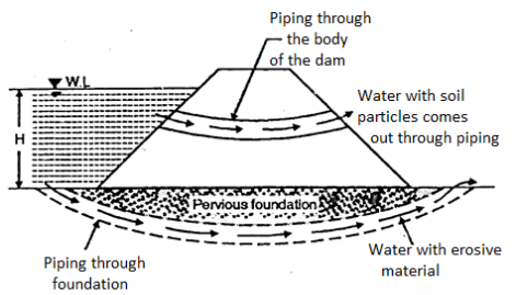
Fig 5: Seepage failure
Piping through dam
- More than 25 % of failures may occurs due to piping due to presence of sand and gravel there may be flow of water causing piping leakage through dam which may lead to failure of dam.
- These may develop due to faulty construction improper compaction. Shrinkage cracks, cracks developed due to settlement of the foundation such effects may be removed by better construction and maintenance.
Piping through foundation
- If soil below foundation is permeable and if foundation strata consist of cavities, then water start seeping through them which may erode the soil causing piping failure.
Sloughing of downstream toe
- It is process in which soil mass falls down after saturation. This may occur due to saturation of downstream toe. It is a type of local slope failure.
- It occurs when downstream portion of dam becomes saturated and continuously remains in same state causing piping failure.
- It may occur due to choking of downstream drains.
3. Structural Failure:
- Structural failures in the earth dams are of following types:
Slides in embankment
- When slope of embankment is too steep for strength of soil then dam may fail due to sliding of embankment.
- The failure of slopes are the one of main cause of failure of earth dams.
- The following three types of slope failure are:
- Upstream slope failure during sudden draw down.
- Downstream slope failure during steady seepage.
- Upstream and downstream slope failure during construction.
Foundation slides
- If the foundation is laid on soft soil, then dam will slide.
- It may also slide if strata consist of weathered rock, shale's etc. i.e., if soft and weak strata exist in foundation. The dam may slide over some expansion of clayee soil on saturation may causes lifting of dam.
Failure by spreading
- Such type of failure may occur when earth dam is located above stratified deposit that contains layers of silt clay.
Failure due to holes caused by burrowing animals
- The burrowing animals dig holes in dam and through these holes free passage of water may occur, which may lead to piping failure.
Failure due holes caused by leaching of salts
- The salt such as gypsum, iron oxide etc. If present in water, abutment and foundation may cause cavities which leads to excessive settlement of dam, which may lead to failure of dam.
- Definition: When flow of water occurs through soil, the top surface of the flow zone is called the phreatic surface, and in section, the top line of flow zone is called the phreatic line.
- In earth retaining structures, the flow due to seepage will cause the phreatic line.
- All the points on the phreatic line have equal seepage pressure and it can be taken as atmospheric pressure. Fig. Shows phreatic lines in different types of earth dams.
- Phreatic or seepage line is the line within a dam section below which there is positive hydrostatic pressure exist in dam and it is atmospheric on it.
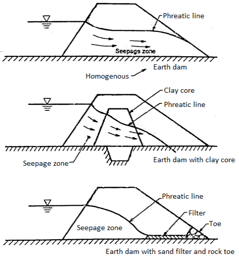
Fig 6: Phreatic lines in earth dam
Plotting of Phreatic Line:
Plotting of phreatic line for a homogeneous earth dam with a horizontal drainage:
- Fig. Shows a homogenous earth dam provided with a horizontal drainage blanket 'DB' at its toe. Distance PQ is equal to 0.30 L, is the horizontal projection 'QR' of the wetted portion of the upstream face.
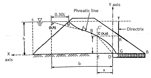
Fig:5.7
- 'Q' is the point of inter section of the water surface with the upstream face. Kozeny has shown the phreatic line which coincides with the base PBF except at the entrance.
- From the known positions of the point P and the focus F, the base parabola PBF can be drawn by graphical method as follows:
Graphical method
- The basic property of the parabola which can be used for drawing the base parabola is as follows. Distance of any point 'C' from the focus is equal to the distance of the same point from the directrix.
∴Distance CF = Distance CR
Where CR =horizontal distance of C from directrix TG
- The directrix 'TG' can be located by drawing an arc with the centre at 'P' and radius equal to PF. When line PQ is extended upto 'T', then arc cuts the line PQ
- A vertical line TG through point T is drawn and line
TG becomes the directrix of the base parabola
∴PF = PT
- By using basic property of the parabola as given in point '1', intermediate points on the base parabola are located.
- By joining all such points, a smooth curve is drawn so as to obtain base parabola PBF. The last point F on the parabola will be the midway between D and G such that DF = FG, the Point F is called as apex or vertex of the base parabola.
In such way, phreatic line QBF can be plotted.
- Stability and development of stresses has prime importance in the design of earthen slopes and has to be carefully studied. An earth embankment generally fails due to the sliding of a large soil mass along a curved surface. Hence stability of slops of an earthen embankment can be studied and examined by a method called as slices method or Swedish slip circle method in which the condition of plane strain with failure along a cylindrical arc and location of the centre of the possible failure arc are assumed.
- In this method, the earth mass is split up into number of vertical segments termed as slices, spacing between the verticals are usually equal 6 to 12 slices are sufficient as per the requirement of accuracy.
- See the Fig. For better understanding.
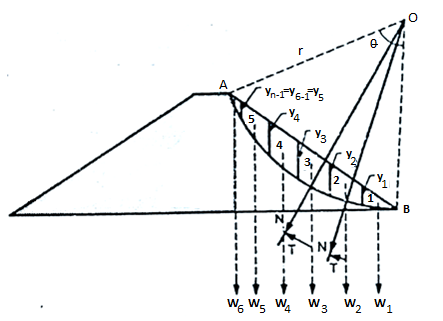
Fig 8: Slices method or Swedish slip circle method
- Consider 'O' be a centre and r is radius of the possible slip surface. The total arc 'AB' is split up into slices having equal width (b) in meters. Note that the width of last slice is somewhat different and let it be m.b meters.
- Slices are numbered as 1,2,3,4,5 +........ And weight of these slices are W₁, W₂, W3, W4, W5 +...The weight W of each slice may be resolved into normal component say N and a tangential component say (T)
N = W cos 
T = W sin 
Where,  = angle which the slope makes with the horizontal.
- Normal component (N) does not produce any moment on the slice because this component passes through the centre of rotation 'O'. But tangential component (T) produces a disturbing moment.
Disturbing moment = T.r
Where, r = radius of the slip circle
- The tangential components of a few slices may develop resisting moments and hence T is taken as negative.

Where, T1+T2+T3+T4+…….
Md= The total disturbing moment
- The magnitude of shear strength produced in each slice depends upon the normal component (N) of that slice.
∴Shear resistance = c. L + N tan
Where, c = unit cohesion
 L= curved length of the slice
 angle of internal friction of soil
- This shear resistance acting at a distance 'r' from the centre 'O' produces a resisting moment.
∴Resisting moment due to shear resistance = r (e x  L + N tan
  ]
]
Total resisting moment over the entire arc AB (MT) = r [c Σ L+ (
L+ ( ) tan
) tan ]
]
= r [c. AB + ( ) tan
) tan ) … (1)
Where,  sum of all the normal components = N₁ + N₂ + N3 + ......
AB= length of slip circle= 
Where,  = angle in degree
∴ Factor of safety against sliding=
∴F.S= 
Or F.S= … (2)
… (2)
- In Equation (2) EN and ET are evaluated separately method of finding
 and
and  is as follows:
 - Y1, y2, y3, y4…... are the vertical boundary ordinates of the slices 1, 2, 3, 4.... Respectively and corresponding weights can be obtained as follows:

.
.
.

Where,  = unit weight of soil and unit width of slice is considered.
n =the total number of slices
- Definition: A structure which is designed to resist the external forces by its own weight is called as gravity dam.
- Design of such dam is done in such way that its own weight resists the external force. Gravity dam structure is more rigid and most durable and requires less maintenance.
- Gravity dam may be constructed of masonry or concrete. Hence concrete dam is a gravity dam. Concrete gravity dam is more preferred these days and mostly constructed.
- Site selection for such dam is prime importance and site for dam should be selected in such way that, there exists a natura! foundation strong enough to take the huge amount of weight of the dam.
- Gravity dam is generally straight in plan and in case of special cases, it may be slightly curve.
Cross-section of Gravity Concrete Dam
- For any suitable conditions, gravity dam may be constructed to greater heights. Grande Dixence dam in Switzerland is highest concrete gravity dam and its height is 284 m and highest concrete gravity dam in India is a Bhakra dam with a height of 226 m.
- In such structure, the ratio of base width to height is less Fig. Shows a typical cross-section of concrete dam than 1.1.
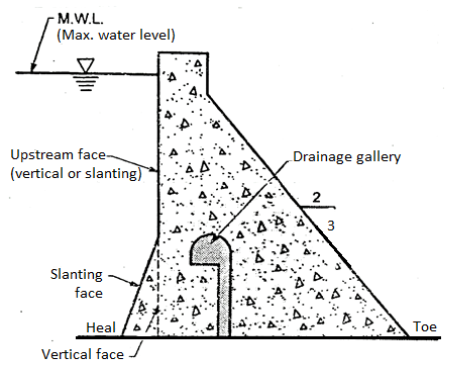
Fig 9: Typical cross section of concrete dam
- To release the uplift pressure, a drainage gallery is provided with respect to base of the dam as shown in Fig. The upstream face of concrete dam may be vertical throughout the height of a dam or partly kept slanting for some of its length as shown in Fig. uplift pressure is caused by the seeping water.
Various types of loading or forces acting on concrete gravity dam are as follows:
- Water pressure (P)
- Silt pressure
- Uplift pressure
- Wave pressure
- Ice pressure
- Weight of the dam
- Earthquake forces or seismic forces
1. Water pressure (P)
- In concrete gravity dam, the water pressure is more major and important external force. The weight of the water stored on the upstream side on the dam exerts the horizontal water pressure and it can be estimated from the rule of hydrostatic pressure distribution. Hydrostatic pressure variation or distribution is triangular in shape as shown in Fig.
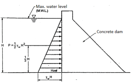
Fig 10: Hydrostatic pressure distribution on u/s side of a dam for upstream face vertical
For vertical upstream face of dam, the intensity of water pressure at the water surface is zero and at the base, it is equal to  .
.
Water pressure at water surface=0
Water pressure at the base = .
.
P = Resultant force caused by external water pressure acting at 1/3H from base =
Where,  = unit weight of water = 9.81 kN/m²
H = depth of water
- For upstream face partly vertical and partly with slope as shown in Fig., then resultant water force (P) is resolved into the components as
- Horizontal component (Ph) = H² acting at H from the base
- Vertical component (Pv) = weight of the water stored in column PQRS and acts at the centre of gravity of area. Note that if there is tail water on the d/s side of dam as shown in Fig. Then resultant force on downstream face of tail water has also the components as
- Horizontal components (Ph’) =
 acts at H’/3 from base
 - Vertical components (Pv’) equal to weight of water stored.
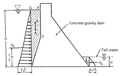
Fig 11: Hydrostatic pressure distribution on u/s side of a dam for upstream face partly vertical and partly inclined
2. Silt pressure:
- Silts are get deposited against the upstream face of the dam. Force exerted by silts with external water pressure can be expressed by Rankine's formula as follows:
 and this silt force acts at h/3 from base
Where, = Silt force or force exerted by silt
 Submerged unit weight of silt material
h = height of silt deposited
Ka = Coefficient of active earth pressure of silt=
Where,  angle of internal friction of soil and cohesion is neglected.
- For upstream inclined face, the vertical weight of the silt supported on the slope also acts as a vertical force. If any data of silt is not available or reliable, then U.S.B.R. Recommendation can be taken into consideration in which deposited silt can be taken as equivalent to a fluid exerting a force with a unit weight equal to 3.6 kN/m3 horizontally and with a unit weight of 9.2 kN/ m3 vertically.
Therefore, the total horizontal force = 3.6 = 1.8 h² kN/m run
And total vertical force = 9.2=4.6h² kN/m run.
In the most of the cases of design, the silt pressure is not taken into account or neglected because in the beginning, the silt load is absent.
3. Uplift pressure:
- Seepage of water is occurred through cracks, fissures and pores of foundation material and also through dam body. This water is then come to bottom through the joints between the dam body and its foundation at the base.
- This seeping water finally exert an uplift pressure on the base of the dam. Hence uplift pressure is major external force and has to be considered in the design of dam.
- Uplift pressure reduces the downward weight of the body of the dam and ultimately affects the dam stability.
- According to the recommendation of United States Bureau of Reclamation (U.S.B.R.), the uplift pressure intensities at the heel and at the toe is equal to their respective hydrostatic pressures and shown by straight lines in between as shown in Fig.
- Fig. Shows uplift pressure diagram i.e., U diagram when drainage gallery is not provided.
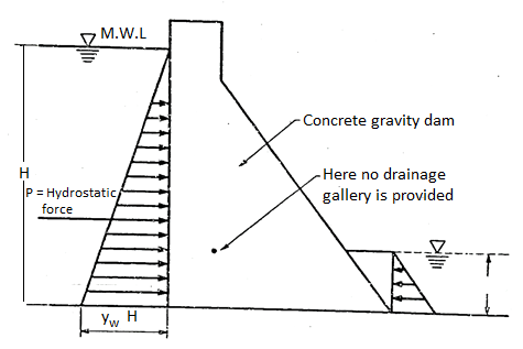
Fig 12: Section of dam

Fig 13: Uplift pressure distribution diagram without drainage gallery
- Fig. Shows uplift pressure diagram when drainage gallery is provided. In this case, it is recommended that the uplift pressure at the base of the drainage gallery is equal to the addition hydrostatic pressure at the toe and one third difference of the hydrostatic pressures at the heel and toe.
∴Uplift pressure = 
- Note that it is considered or assumed that earthquake forces do not affect the uplift pressure.
Remedial measures:
- Uplift pressure can be controlled by constructing the following three things:
- Cut-off walls under upstream side
- Drainage channels between dam and its foundation
- Pressure grouting to the foundation.
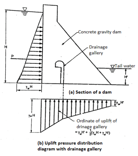
Fig 14: Uplift pressure diagram with provision of drainage gallery
4. Wave pressure
- When the wind blows, the waves are produced on the surface of stored water in the reservoir. These waves produce wave pressure towards the downstream side.
- Wave pressure developed on the surface of reservoir depends upon the wave height.
Let hw = wave height
 ...for F< 32 km … (1)
hw=0.032 ... For F> 32 km …. (2)
Where,
F= Fetch or straight length of water expanse in km
V = Wind velocity in km/hr.
Let, Pw = maximum pressure intensity caused by wave action acting at meters above the still water surface
∴
- The pressure distribution due to wave action can be assumed as triangular with a height of 5/3hw has shown in Fig.
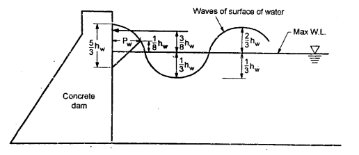
Fig 15: Wave action and its pressure distribution on U/s side of a dam
Pw = Total wave force=
∴ =2
=2
Total force (Pw) caused by wave action acts at 3/8 h above water surface of reservoir.
5. Ice pressure:
- In cold region of countries, ice is formed on the surface of the reservoir, which further can expand or melt. Hence the dam face should able to resist the force exerted by the melting ice which has magnitudes varies from 250 kN/m² to 1500 kN/m² depending upon the atmospheric temperature.
- For the sake of design, the average value like 50 kN/m² can be allowed and considered under the ordinary conditions.
6. Weight of the dam
- The weight of the dam and its foundation has prime importance because they are major resisting force. A unit length of the dam is taken in two-dimensional (2-D) analysis. The overall cross section of dam is split up into triangles and rectangles of which, weight with their centre of gravity is determined.
- Then resultant of all downward forces gives the total weight of the dam which acts through centre of gravity of the dam.
7. Earthquake forces or seismic forces:
- In the earthquake prone area, if the dam is to be constructed, then earthquake impact should be considered.
- The effect of an earthquake is equivalent to give an acceleration to the foundation of the dam in the direction in which the waves travel at the moment.
- Earthquake waves can be moved in any direction’s sake of design, the earthquake wave force should be resolved horizontally and vertically or resolved into horizontal and vertical components.
- Therefore, the accelerations developed by an earthquake has to be taken account.
- Let an = horizontal acceleration and av = vertical acceleration.
- The value of accelerations are generally expressed in percentage of acceleration because of gravity (g) and they are considered as a 0.1g or
 =0.2 g.
 - For high dam in earthquake zone, the average value of a taken from 0.1 g to 0.15 g and the area which is not subjected to extreme seismic, the value an = 0.1g and av = 0.05 g is taken in design. The area which is not subjected to earthquakes, the value of acceleration is neglected.
- When a dam is located in a seismic region, then it should be designed for seismic or earthquake forces. If the dam is designed by considering the intensity of seismic forces, then dam is capable to resist the seismic forces and it will not be damaged during earthquake likely to occur during its life,
- The dam has to resist the inertia forces caused by the sudden movement of earth's crust, hence inertia forces should be considered in the design of dam so as to avoid failure.
- The magnitude of the seismic forces depends upon the following factors:
- Severity of earthquake
- Mass of the dam
- Elasticity of the material of the dam
- The earthquake acceleration is usually expressed as a fraction of the acceleration because of gravity (g).
- Earthquake acceleration =
 g
g - Where α = seismic coefficient
- The value of seismic coefficient (a) can be determined by two methods as:
- Seismic coefficient method
- Response spectrum method
Seismic analysis when dam in full condition:
- Then the dam is full of water with its capacity, danger situation occurs such that acceleration due to earthquake acts towards the downstream direction and the corresponding inertia force act in the upstream direction.
Seismic analysis when dam in empty condition:
- When the dam is empty, danger situation occurs when the acceleration caused by earthquake acts towards the downstream direction and inertia force acts in the upstream direction.
Horizontal force
The horizontal force caused by earthquake is given as:
Fh=M x horizontal acceleration
Where Fh =Horizontal force due to earthquake
M =Mass of the dam
Earthquake acceleration is expressed as a  g and mass of dam is equal to weight W divided by g i.e., M= W/g
∴
Fh is assumed to act at the centre of gravity of mass.
Vertical force
The inertia forces act on the dam and the water due to vertical acceleration magnitude of vertical force is given as:
Fv = M x vertical acceleration
Where Fv =Vertical force
M =Mass of the dam
∴
Where, g = vertical acceleration
- As it is proved and experienced form the past years history, earthquakes are very dangerous and un-controlling natural disaster phenomenon.
- It can be predicted but with the state-of-the-art technologies it is possible to find the probability of earthquake occurrence for a given place, provided enough seismic data is available.
- But it is not possible to exactly predict the earthquake when it is going to strike, where exactly its epicenter is going to be located, what would be its magnitude, etc.
- Earthquake damages the structures like dam, reservoir. Dam structure instantly collapse without any warnings, during the unpredictable and sudden earthquakes.
- It is not feasible and economical to design and construct totally earthquake proof building structures, particularly to withstand very severe earthquakes of magnitude above 8.0 (Richter Scale).
- But it is very much possible to design and construct earthquake resistant building structures, though they may suffer huge damage under the influence of very severe earthquakes, they may not suddenly collapse and will not kill people. Thus, safety of people and contents is assured in earthquake resistant building and thereby a disaster is avoided.
- Collapse of dams during earthquakes can cause flooding in the downstream reaches, which itself can be a secondary disaster. Therefore, dams (and similarly, nuclear power plants) should be designed for still higher level of earthquake motion.
- For the safe earthquake resistant design, follow design principles and zoning as per the provision made in various codes published by Bureau of Indian Standards. The Indian seismic codes are IS: 1893, IS: 4326, IS:13827, IS:13828, IS: 13920 and IS:13935.
- Some of the following points to be followed to construct the safe earthquake resistant dam structures:
- The foundation should be provided over the hard rock with no sign of faults.
- Min. 16 mm diameter reinforcing bar should be used in all structural members of RCC dam.
- Double reinforced should be provided in case of RCC dam structures.
- Ductile materials shall be used to construct the structures.
- Masonry structures with stones or bricks as foundation material should be avoided.
- A rare few earthquakes have been associated with the buildup of large masses of water behind dams, such as the Kariba Darn in Zambia, Africa.
- World's largest reservoir-induced earthquake occurred on December 10,1967 in the Koyna region of western Maharashtra in India. It had a magnitude of 6.3 on the Richter scale.
A gravity dam can fail because of the subsequent reasons:
- Overturning of the dam
- Sliding of the dam
- Crushing of the dam or Foundation
- Development of anxiety withinside the dam.
1. Overturning of the Dam.
- If the consequent of all of the feasible forces (inner in addition to external) appearing at the dam cuts the bottom of the dam downstream of the Toe, the darn might overturn until it could face up to tensile stresses.
- To guard the dam towards overturning, the consequent of the forces have to by no means be allowed to head down circulation of the Toe.
- If resultant is maintained in the frame of the dam, there might be no overturning.
- All the forces appearing at the dam purpose moments.
- Some of the forces assist hold balance of the dam, at the same time as others attempt to disturb the stableness.
- The moments of the forces, assisting dam to hold its balance are recognize resisting moments (Mr).
- The moments of the forces that attempt to disturb the stableness of the dam are referred to as overturning moments (Mo).
- As quickly as Mo exceeds Mr overturn of the dam might take place. Factor of safety (F.S.) towards overturning may be observed out as follows.
- F.S=Resisting moment/Overturning−moment=M0/Mr
- The value of F.S. Against overturning should not be less than 1
2.Sliding of the Dam.
- In this mode of failure, the dam fails in sliding.
- The dam as an entire slide over its basis or one a part of the dam might also additionally slide over a part of the dam itself, mendacity underneath it.
- This failure happens while the horizontal forces inflicting sliding are extra than the resistance to be had to it, at that level.
- The resistance in opposition to sliding can be because of friction by myself or it is able to be because of a mixture of friction and shear electricity of the joint. Shear electricity develops at the bottom if benched basis is provided.
- At different joints the shear electricity is evolved with the aid of using laying joints cautiously with the intention to acquire top bond.
- Interlocking of stone blocks in stone masonry additionally facilitates boom shear electricity.
- In case of low masonry dams shear electricity isn't always taken into account.
- In that case aspect of protection in opposition to sliding is acquired with the aid of using dividing internet vertical forces with the aid of using internet horizontal forces and multiplying the ensuing with the aid of using coefficient of friction μ.
∴Sliding factor =
Where µ = Coefficient of friction.
∑ (V – U) = Net vertical force.
∑H = Sum of the horizontal forces causing sliding
- The value of coefficient of friction varies from 0.65 to 0.75. The value of F.S. Should always be greater than one.
3. Crushing or Compression Failure.
- If the compressive strain advanced everywhere withinside the dam exceeds the secure permissible limit, the dam may also fail with the aid of using crushing of the dam itself or of foundation.
- The most compressive strain can increase at toe while reservoir is complete of water.
- If reservoir is empty the most compressive strain is probable to increase on the heal of the dam.
- The value of most compressive and minimal compressive stresses may be discovered out with the aid of using the use of following equation.

Where  = Algebraic sum of vertical force = self weight (w)=e=B/6
B= Base width
4. Failure because of Development of Tension.
- Both cement concrete and masonry, are very vulnerable in anxiety.
- Hence from protection factor of view the anxiety isn't always allowed to be advanced withinside the dam everywhere.
- We realize that minimal compressive strain withinside the dam.
- The nature of this strain remains
- Negative signal of this strain shows that nature of this strain is tensile in place of compressive.
- Hence as quickly as e exceeds 6 b anxiety is advanced withinside the dam and dam fail through establishing of the joints, as concrete and masonry are nearly nil in anxiety.
- When reservoir is complete of water, anxiety is probable to expand at heal and while reservoir is empty anxiety is probable to expand at Toe of the dam.
- In different phrases it may be said that till resultant of the forces lies withinside the center 1/3 width of the bottom anxiety cannot expand everywhere withinside the dam.
- In the case of gravity dams, having mild height, no anxiety is permitted to be advanced everywhere.
- However, in case of very excessive dams, a small tensile strain can be accepted to be advanced, however simplest for quick periods at some stage in heaving floods or earthquakes.
- Once tensile cracks expand at heel, the dam can't be rendered safe.
- Due to anxiety cracks, uplift strain receives extended and therefore internet vertical downward pressure is decreased.
- This reasons in addition transferring of the ensuing in the direction of the Toe and this results in in addition lengthening of the cracks.
- Due to lengthening of the cracks, powerful width of base is in addition decreased and compressive strain at toe in addition will increase.
- Ultimately compressive strain at toe will increase to such a volume that dam fails through crushing at Toe.
- Fig. Shows a right-angled triangle which is an elementary profile of a gravity dam subjected only to the external water pressure on upstream side. This right-angled triangle has zero width at the water level and base width say 'B' at the bottom.
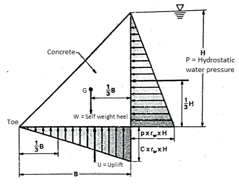
Fig 16: Elementary profile of a gravity dam
- Shape of elementary profile of a dam is quite same to the shape of the hydrostatic pressure distribution.
When the reservoir is empty
- For empty reservoir, self-weight (w) of the dam is an only single force acting on a dam and this self-weight acts at a distance 1/3B from the heel.
- Line of action of self-weight 'w' impart the maximum possible stabilizing moment about the toe without developing the tension at toe.
- For empty reservoir, the vertical stress distribution at the base is given by the following relations.


Where  = Algebraic sum of vertical force = self-weight (w)=e=B/6
B= Base width
 Maximum vertical stress
 Minimum vertical stress

∴ … (1)
… (1)
∴
∴
Therefore, it has been proved that the maximum vertical 2w/B stress equal to which acts at the bevel and the vertical stress is zero at toe.
When the reservoir is full
- Condition 1: The resultant (R) of hydrostatic water pressure (P) self-weight (w) and internal water pressure or uplift pressure passes through lower mid le third point.
- Condition 2: For full reservoir condition, the dam is safe in sliding.
In the design aspect, the stability analysis of gravity dam has prime importance. The stability of a gravity dam can be analyzed by two-dimensional gravity method approximately and easily and it can be precisely or accurately analyzed by three dimensional methods like slab analogy method, trial load twist method or by experiment on model.
Two-Dimensional (2-D) Stability Analysis or Gravity Method
- Initially in case of preliminary analysis of all gravity dam, a typical cross-section of the dam of a unit width is considered. This cross-section is considered or assumed to behave independently of the adjoining section. Note that if the vertical joints of the dam are not grouted, then this assumption is nearly true.
- For wide U-shaped valleys, this assumption is nearly satisfied because the transverse joints are not generally grouted: whereas for V-shaped valleys, this assumption gives some errors because transverse joints are generally grouted and complete length of the dam act as a single body.
- Preliminary design can be analyzed by gravity method and precise design can be done by any of the available three-dimensional methods. We have used only two-dimensional analysis in this chapter because three-dimensional analysis is not in syllabus.
Assumptions made in two-dimensional analysis of gravity dam:
- Following are the various assumptions made in the 2-D analysis or design of concrete gravity dam.
- By beam action, no loads are transferred to the abutments.
- The dam is assumed to be composed of a number of cantilevers. Each cantilever is 1 m thick and acts independent of other.
- The material in the foundation and the body are assumed to be homogeneous and isotropic (i.e., having equal elastic properties in all direction)
- The foundation and dam are assumed to be a single unit or monolithic.
- Movement of the foundation caused by transference of load is not considered.
- The stresses induced in the foundation and body of the dam should not exceed the elastic limit.
- Small openings done in the body of the dam for any purpose do not affect the general stress distribution and only produce local effects
Procedure of two-dimensional analysis for stability of the gravity dam:
- There are two methods of dimensional
- Analytical method
- Graphical method
Analytical method:
- The stability of gravity dam can be analyzed in following way:
- Initially consider the unit length of the dam.
- Whatever vertical forces acting on dam are determined in magnitude and direction. Then find the algebraic sum of vertical forces i.e.,

- Horizontal forces acting on the dam are determined in magnitude and direction and then algebraic horizontal force i.e.,
 are determined.
 - Lever arm of all vertical and horizontal forces about the toe is determined.
- Moments of all forces acting on dam about toe are found out and them algebraic sum of all the moments about the toe i.e.,
 is determined.
 - Then location of distance the resultant force from the toe is determined as follows:

∴ = distance of resultant force from the toe
- Eccentricity (e) of the resultant force (R) is determined by following formula:

- Note that eccentricity (e) should be less than B / 6, which confirms that no tension is developed in the dam anywhere at any point.
- Then vertical stresses at the toe and heel are determined by using the following formula:

Where, Pv = vertical direct stress:
e = eccentricity
 = algebraic sum of vertical forces
B= base width of dam
- Note that sometimes stresses are determined by neglecting uplift.
Refer to the Fig. For better understanding.

Fig 17: Principal and shear stresses on the dam


- Note that face of the dam will act as a principal plane because the water pressure (p’) acts at the right angles to the face with any shear stress on this plane.
- The maximum normal stresses should not exceed the maximum allowable values. The crushing strength of the concrete varies between 1500 kN/m² to 3000 kN / m² depending upon the grade of concrete M15 to M30.
- Factor of safety (F. S.) against overturning is determined.
∴F.S. =
- + ve sign for anticlockwise moment and - ve sign for the clockwise moment is considered in finding the factor of safety (F. S.).
- Then factor of safety against sliding is determined by using sliding factor.
∴Sliding factor =
Shear friction factor (S.F.F) =
Where, B = width of the dam at the joint
q = average shear strength of the joint
- For poor rocks, q is about 1400 kN/m² and for good rocks, it is about 4000 kN/m².
μ = coefficient of friction varying its value from 0.65 to 0.75.
Note:
- Sliding factor (S.F.) should be greater than 1 i.e., S.F.> 1.
- Shear friction factor (S.F.F.) should be greater than 3 to 5 i.e., S.F.F.> 3 to 5.
- Stability analysis should be done for full reservoir and for empty reservoir.
Graphical method:
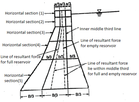
Fig 18: Graphical method
- In this method, the complete dam section is split up into a number of horizontal sections at some suitable intervals as shown in Fig. Dam section is divided into the horizontal sections specifically at the places where slope changes.
- Determine the sum of vertical force i.e.,
 and sum of the vertical forces
  acting on each section and then resultant (R) of
  and
and  is drawn graphically for each section and then dotted lines are joined at all points where the individual resultants cut the individual horizontal section as shown in Fig.
 - This entire dotted line represents the resultant force (R) and it should be line within the middle third so as to avoid the development of tension.
- This procedure should be performed for both the cases such as full reservoir and empty reservoir. Position of resultant in both the cases should lie within middle third for non-development of tension.
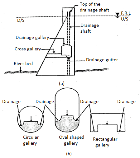
Fig 19: Various shapes of Drainage Galleries
- Gallery is a passage provided in the body of dam.
- These may run parallel or transverse to the axis of dam and located at different levels.
- These all are inter connected by shaft, lifts, stair etc. The usual sizes of galleries are 2 to 2.5 m wide and 2.5 to 4m deep and corners are rounded.
Functions of Drainage Galleries in Dam:
- The purpose of providing galleries are:
- For inspection of dam from inside.
- To drain off seepage water through the body of dam.
- It provides access to spillway gate.
- It helps in locating pumps, observation devices.
- It provides access for grouting.
Types of Drainage Galleries in Dam:
- Foundation gallery (drainage gallery)
- Inspection gallery
1. Foundation gallery (Drainage gallery)
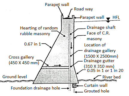
Fig 20: Drainage gallery
- It is provided near to the rock foundation. Its main function is to drain off the water which percolates through the foundation.
- It varies from 1.5 x 2.2 m to 1.8 x 2.4 m after completing foundation grouting drainage holes are drilled to collect seepage water and then it is drained off by cross galleries.
2. Inspection gallery
- The water seeps through body of dam is collected by various galleries. These are inter connected by vertical shafts.
- These provides access to the interior of dam for inspection purpose and also helps in draining off seepage water.
The various types of joints used in gravity dam are:
- Construction
- Expansion-Contraction
- Transverse joint
- Longitudinal joint
1. Construction joints
- Construction joints are in horizontal plane and in vertical plane. These are provided for ease in construction of dam.
- Generally, in gravity dam concrete is placed in lifts so as to avoid heat of hydration at the same time horizontal joints are introduced between successive lifts of concrete.
- To develop proper bond between two lifts the top surface of the concrete laid in lower lift is freed of by brushing to remove foreign material. Sometime wet sand blasting is used.
- The surface is roughened and 1.25 cm thick layer of rich cement mortar is applied to develop proper bond between lower lift and new concrete.
2. Expansion and contraction joints
- The cracks are formed mainly due to shrinkage of concrete, tensile stresses formed in concrete and temperature variations, and if these are not properly controlled by providing suitable contraction joint, they destroy monolithic action of the structure.
- Therefore, suitable contraction joints are provided in gravity dam.
- The two types of contraction joints are:
a. Transverse joint
- These are provided normal to the axis of dam. These are vertical and extend from foundation to the top of dam. These joints allow contraction and prevent cracks in the dam.
- Its spacing depends upon various factors such as topography of site, temperature and its variation etc. the usual spacing of joint is between 12 to 18 m. The joint is filled with as plastic joint filler.
b. Longitudinal joint
- These are provided parallel to the axis of dam to prevent longitudinal axis.
- The spacing of longitudinal joint is limited to 15 m and 30 depending upon foundation condition.
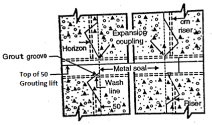
Fig 21: Longitudinal joint
- The large concrete blocks between the joints may crack because of high temperature gradient between the interior and the surface and this is caused by improper temperature control.
- Due to improper temperature control, these large blocks of concrete are subjected to deep as well as surface cracking.
- The interior cracking of concrete blocks are caused by heat of hydration produced by cement and hence giving rise to high temperature gradient surface cracks may be caused by daily vibrations of the temperature at surface.
- Note that surface cracks are more harmful because the disintegration starts through them by wedge action. Widening and deepening of cracks are caused by the entry of water through surface cracks and further water solidifies and ice so formed starts to expand at 4°C.
Remedial Measure or Control of Crack Formation in Dams:
- Following are some of the remedial measures employed to minimize or to reduce the development of the cracks in mass concreting work as in gravity dam.
- Pre-cooling of concrete
- The concrete is cooled before it is placed. This is done by cooling the aggregate by refrigerated water, blowing air through them, cooling of sand sometimes, refrigerated water can be used to manufacture of concrete.
2. Post-cooling of concrete
- In this case, refrigerated water is circulated through pipes which are embedded in concrete in each lift. The cooling process get started immediately after a block of concrete is laid and process is further continued till the temperature falls to mean annual temperature of the locality.
- Thin-walled tubing with expansion coupling are made into coils and placed in the middle of each lift for the purposes of circulating the cool water.
3. Control of cracking can be achieved by providing contraction joints at suitable spacing's.
4. Control of cracking can be achieved by using low heat cement for the concrete.
5. Control of cracking can be done by restricting the height of lift upto 1.5 m.
6. Control of cracking can also done by using lower percentage of cement in the concrete for the interior of the blocks say about 80% of that for the exterior.
- It is an arrangement provided at the crest of dam to expel the excess water rises above the full reservoir level.
- This is necessary otherwise water will go on rising even above HFL and will start flowing from top of dam which may affect stability of dam.
- Therefore, it is very essential to provides spillway to dispose surplus water on downstream side.
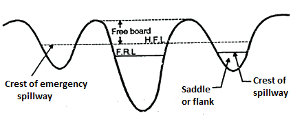
Fig 22: Location of Spillway
- The component part of spillway are:
- Body or spillway
- Energy dissipators
- Approach channel
- Tail Channel
- Guide wall.
- Definition: The passage provided for disposal of surplus flood water on the downstream side without affecting stability of dam are called as spillways.
- Sometimes gates are provided to control flow over the spillway crest.
Location of Spillway
- Spillway are located at
- In the body of damn.
- At one end of the dam.
- Away from the body of damn independently.
- Generally, in gravity dam spillways are provided in the body of dam.
- Separate spillway is provided in case of earthen dam.
Essential Requirement of Spillway:
The various essential requirement of spillways are:
- It must have adequate discharge capacity.
- It should be provided with some device for energy dissipation.
- Its discharge should be such that it should not cause flooding on downstream side.
- It must be safe.
- Its surface must be erosion resistant.
- It should be so located that it should not erode downstream toe of dam.
Component Part of Spillway:
- Body, weir or spillway
- Approach channel
- Energy dissipators
- Tail channel
- Guide wall
- Discharge channel
Body, weir or spillway
- The weir or body may be ogee shaped, U shaped, semicircular or circular. These are sometimes provided with gates to control or regulate flow of water.
Approach channel
- It draws excess water form reservoir and directed it to downstream side.
- It admits water when its level goes above FRL into the spillway thus helps in controlling discharge.
Energy dissipators
- When water flows over from crest it falls rapidly depending upon height of crest, due to its high velocity it may scour the downstream end and may damage the dam.
- Therefore, energy dissipators are provided at downstream end of the discharge channel. Generally, ski jump bucket, roller bucket or some other suitable devices a provided to dissipate the energy.
Tail channel
- It conveys spillway discharge to the downstream side.
Guide wall
- It guides the water to flow directly into the river downstream.
Discharge channel
- The main function of discharge channel is to convey the water safely from reservoir downward to the river.
Factors Affecting Spillway Capacity
- The various factors which affect spillway capacity are as follows:
- In flow.
- Capacity of outlet.
- Possible damage.
- Available storage capacity.
- Gates of spillway.
- Site condition.
- Type of dam and its purpose.
- Height of the crest of spillway.
- Solid material brought by river its nature and at
- Geological condition.
Types of Spillways based on operation
- Emergency spillway
- Service spillway
- Axillary spillway
1. Emergency Spillway
- It is provided with an earthen dam. In such spillway part of the length of earthen dam is kept weak above FTL/FRL (Full tank/Reservoir level).
- When abnormal high intensity flood occurs the weaker portion gets washed and flood water flows through that portion which acts as additional spillway and thus avoids possibility of failure of the dam.
- The various conditions which may lead to emergency are:
- When there is mal functioning of spillway gate.
- When actual flood exceeds the design flood etc.

Fig 23: Emergency spillway
2. Service Spillways or main spillway:
- The service spillways are masonry or concrete structure provided with necessary component. It is necessary for all dams and in most dam it is the only spillway designed to pass design flood.
3. Auxiliary spillway:
- This type of spillway is provided so as to supplement the main spillway. It operates only when the design floods in the main spillway is more or exceed.
Classification of Spillway Based on Gates:
- Spillway are classified into various types based on gates as follows:
- Gated spillway
- Ungated spillway or uncontrolled spillway
1. Gated spillway
- Gates are provided over the crest of spillway. It stores more water and efficiently and effectively control the outflow from upstream and downstream side.
2. Ungated spillway or uncontrolled spillway
- In such type, no gates are provided over the crest to control the flow and hence it does not need any operation of gate. Surplus flow of water cannot be controlled by ungated spillway.
Classification of Spillway Based on Features
- Ogee Spillway
- Bar Spillway
- Straight drop spillway or free overfall spillway
- Side channel spillway.
- Chute or open channel or trough spillway
- Shaft spillway or moming glory spillway
- Siphon spillway
- Saddle siphon spillway
- Volute siphon spillway
8. Tunnel spillway
9. Stepped spillway
10. Saddle spillway
1.Ogee Spillway
- The shape of spillway is ogee or S shaped. The main difference between free overfall spillway and ogee spillway is that in case of free overfall spillway water flowing over the crest of spillway drops vertically as free set where in ogee shaped spillway water is guided smoothly over the crest and is made to guide over the downstream face of the spillway.
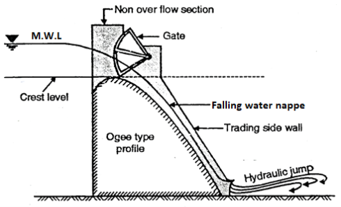
Fig 24: Ogee Spillway
- It is ideal spillway as water flowing over the crest of spillway always remains in contact with the surface spillway.
2. Bar Spillway
- It consists of rectangular masonry concrete bar with crest width1 to 1.5 m.
- It is low height spillway, founded on concrete block, rest on hard rock foundation sometime precast concrete blocks are used for coping of the crest.
- The top of crest is at FRL.
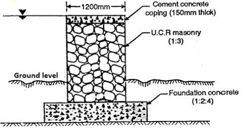
Fig 25: Bar Spillway
3. Straight drop spillway or free overfall spillway or Vertical drop Spillway
- Definition: The spillway in which the flow drops freely from the crest is called as straight drop spillway or free overfall spillway. Such type of spillway is not suitable for high drops.
- Fig. Shows the free overfall spillway with provision of protection on downstream side.
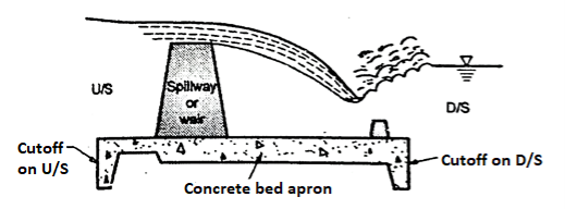
Fig 26: Straight drop spillway provided by protection on d/s side
Three provisions or Methods to avoid erosion on the d/s side
- An artificial pool can be created by constructing a low auxiliary dam downstream of the main structure.
- By excavating a basin which is then provided with a concrete apron.
- Floor blocks and an end sill can be provided as shown in Fig., to help in the establishment of the jump and thus reduces the d/s scour.
- If tailwater depths are sufficient, then a hydraulic jump forms when jet falls freely from the crest, in such case, a long flat concrete apron may be provided.
4. Side channel spillway
- When it is not possible to use overfall spillway especially in embankment dams, then side channel spillway is more suitable. In such type of spillway, water flow after passing over the crest is further conveyed in the side channel which running parallel to the crest as shown in Fig.
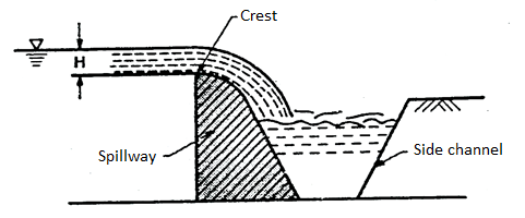
Fig 27: Side channel Spillway
- This type of channel is preferred under following situations:
- It is adopted in case of a long overflow crest provided to limit the surcharge head.
- It is adopted or preferred when the control structure is to be joined to a narrow discharge channel.
- It is preferred when the abutments are very steep.
5. Chute or open channel or trough spillway
- In case of concrete gravity dams, when the spillway is located within the dam body in the same valley, then an ogee spillway is more suitable. However, in case of earthen dam or rockfill dams, a separate spillway and but away from main valley is generally constructed in a saddle or in a flank.
- Even in case of gravity dam, if the main valley is narrow, then a separate spillway is required to be provided. In such situation, a separate spillway like chute spillway or trough spillway is the best option because this type of spillway is a simplest type, lighter and suitable for any type of foundation. In addition to this, it can be easily constructed and provided independently with low cost.
- Chute spillway or trough spillway can easily be provided on earth fill dam and rockfill dam. Chute spillway is sometimes termed as a waste weir.
Construction of chute spillway
- It consists of a steeply sloping open channel placed along a dam abutment, leading the water from the reservoir to the downstream channel below it.
- Base of the channel is generally constructed in R.C. C. With a slab thickness of 250mm to 500 mm. Light reinforcement of about 0.25% of the concrete area can be provided in the top of the slab in both directions.
- Normally chute have constant width but so as to achieve the economy, it made narrowed and then made widened near the end to reduce the discharge velocity.
- Expansion joints are provided in the chute at the interval of about 10m under drains are also provided.
6. Shaft spillway or morning glory spillway
- This type of spillway consists of a vertical flaring funnel act as the crest of the spillway and its bottom end connected to the shaft either vertical or inclined which is further connected at its lower and to a horizontal tunnel extending through or around the dam as shown in Fig. The water flow passes though tunnel is taken to the downstream river channel.
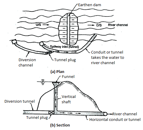
Fig 28: Shaft spillway
- In this type, the water enter into the funnel drops through a sloping or vertical shaft and conveyed to the river channel through a horizontal conduit.
7. Siphon spillway
- This type of a spillway is more suitable when the discharge to be carried is not large and available space is small or limited.
- The siphon spillway automatically maintains the water surface elevation in the dam within the limited range by siphonic action.
- It consists of a closed U-shaped inverted conduit provided with the inlet, short upper leg and throat portion. Siphon spillway taken the water from upstream side of dam to the downstream side of the dam by the principle of siphonic action. Fig. Shows siphon discharging freely.

Fig: 5.29
8. Tunnel spillway
- Definition: The tunnel spillway in which discharge of water can be conveyed by a closed channel around or under the dam. It is also called as conduit spillway.
- The closed channel can be in the form of the vertical shaft or inclined shaft or in the form of a horizontal tunnel.
- This type of spillway is designed so as to flow partly full because full flow due to siphonic action which may develop the negative pressure. In order to maintain free flow, the ratio of area of flow to the total conduit area is often limited to about 75 %. So as to avoid also unsteady flow through spillway, air vents are also provided at various critical points and junction.
9.Stepped spillway
- This type of spillway has been used for over 3000 years. Now a days new construction material like RCC gabions and design technique have increased the interest of stepped spillways and chutes. The steps in spillway produce considerable energy dissipation along chute.
- Stepped spillway also reduces the size of the required downstream energy dissipation basin Fig. Shows the stepped spillway.
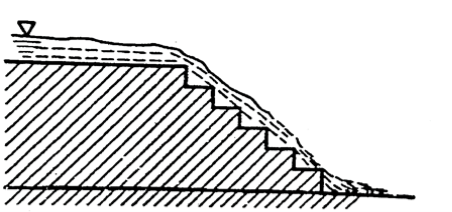
Fig 30: stepped spillway
10. Saddle spillway
- There may be one or more natural depressions or saddles providing spillway in some basins formed by a dam.
- A site which has a saddle is very desirable and economical, if the saddle is suitable for locating the spillway.
- Fig. Shows saddle spillway. This type of spillway is constructed when any of the above type of spillway is not possible. It is usually necessary for the saddle to be on firm rock.
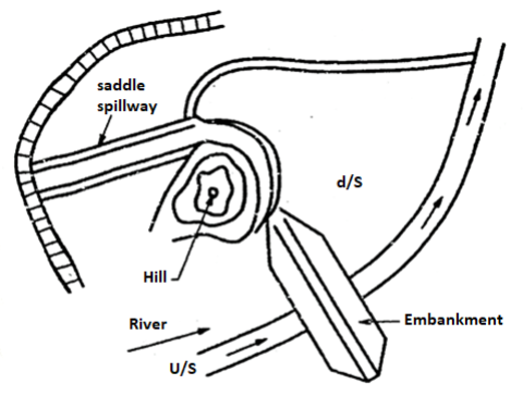
Fig: 5.31
- Ogee spillway or overflow spillway is the most common type of spillway provided on gravity dam profile of ogee spillway is S shaped or ogee overflow or ogee spillway are classified high and low spillway depends upon of the height of the spillway (P) crest measured from the river bed to the design head (Hd).
- Head (H)
- Design head (Hd)
- Head due to velocity of approach (Ha)
- Total energy head (He)
Head (H)
- Definition: The distance measured vertically from the water surface in upstream to the crest axis is called as head (H).
Design head (Hd)
- Definition: The value of head for which the ogee profile is designed, is called as design head (Hd).
Head due to velocity of approach (H₂)
- Head due to velocity of approach is the velocity head given by following expression

Where Va = Velocity of approach
Total energy head (He)
- When the actual head is added in the head due to velocity approach, then it gives total energy head (He).
∴
If H = Hd, then He = Hd + Ha,
Where Hd = design head and Ha = head due to velocity approach.
Design:
Following are the various steps involved in the design of spillway:
- Computation of design head.
- Crest profile for vertical upstream face
- Design criteria of downstream profile
- Design criteria of upstream crest profile
3. Crest profile for inclined upstream face.
4. Design of downstream bucket.
1. Computation of design head
- Q=

Where Q = Discharge
Cd= Variable coefficient of discharge
He= Total head on the crest including velocity of approach head=H+Ha
Le= Effective length of crest
- If

Overflow spillway for which the effect of velocity of approach is negligible.
- If
 <1.33, it is low overflow spillway.
If  exceeds 1.7, the downstream apron is found to have negligible effect on coefficient of discharge. However, for lower values of this ratio, the actual coefficient of discharge (Ca) is lower.
- Fig. Shows downstream apron interference.
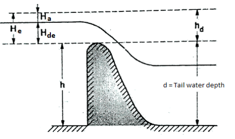
Fig 32: Downstream apron interference
- From the geometry of the Fig., it gives
hd + d = P + Hde
Effective length (Le) of the crest=L-2(NKp + Ka) He
Where, Le = effective length of the crest;
L = net length of the crest;
N = Number of piers;
Kp= Pier contraction coefficient;
Ka = abutment contraction coefficient
- Pier contraction coefficients depends upon the following factors:
- Shape and location of pier nose
- Thickness of pier
- Approach velocity
- Actual head of flow in relation to the design head.
Table: Value of Kp
Sr.no | Pier condition | Pier contraction coefficient |
1 | Pointed nose piers | 0 |
2 | Round nose piers | 0.01 |
3 | Square nose piers with corners rounded on a radius equal to 0.1 of pier thickness | 0.02 |
- The value of pier contraction coefficient (Ka) for the flow under the design head is given in following Table
Table: Value of Ka
Sr.no. | Abutment condition | Abutment contraction coefficient (Ka) |
1 | Rounded abutment where r>0.5Hd where Hd= design head and r= radius of rounded abutment | Zero |
2 | Rounded abutment with head wall at 90 degrees to the direction of flow when 0.5Hd  | 0.10 |
3 | Square abutment with head wall at 90 degrees to the direction of flow. | 0.2 |
Factor affecting coefficient of discharge (Cd)
Following are the various factors affecting the coefficient of discharge (Cd).
- Ratio of actual total head (H) to design total head (Hd).
IS: 6934-1973 gives the coefficient of discharge 'Cd' as the function of H/Hd for the crest profile given for vertical upstream face as shown in Fig
When H = Hd, the value of Cd = 2.2 for high overflow Spillway
II. Depth of approach channel below spillway crest. The height 'h' of the spillway crest above bed of approach channel or above stream bed affects the velocity of approach (Va) and indirectly affects the coefficient of discharge. When h 1.33 H, the effect of velocity is negligible.
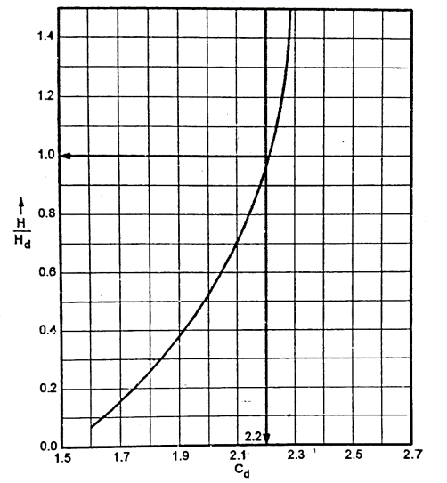
Fig 33: Variation of Cd with H/Hd
III. Downstream submergence
Because of downstream submergence, the coefficient of discharge is reduced. In such case, coefficient of submerged discharge (C₂) and depth of submergence (h,) are taken into consideration for discharge. Hence discharge in such case is given by the following expression.
∴Q=
See Fig. Which shows the variation of ratio with the degree of downstream of submerged discharge.
IV. Downstream apron interference
Fig. Shows the effect of downstream apron interference on coefficient of discharge (Cd).

Fig 34: Downstream submergence
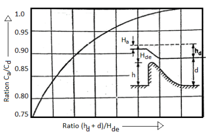
Fig 35: Downstream apron interference
If  >1.7, the d/s stream effect on coefficient of discharge is negligible.
From the geometry of the Fig., we can write as,
hd+d=h+Hde
V. Slope of u/s face of spillway.
- In the ratio h/Hde is small, a spillway with sloping u/s face is little bit higher value of Cd than for the spillway with vertical u/s face.
2. Crest profile for vertical upstream face
(a) Design criteria for downstream profile
Downstream crest profile for vertical upstream face is as shown in Fig.
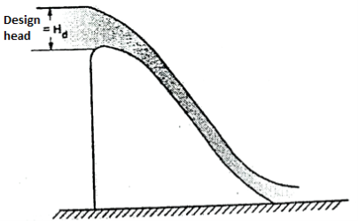
Fig 36: Ogee spillway at design flow
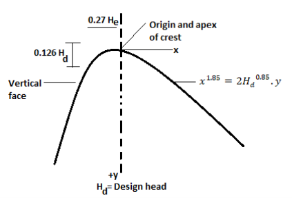
Fig 37: Detail of nappe shaped crest profile
In this case equation for the downstream curve of the ogee is as follows:

Where x and y = the co-ordinates of the crest profile measured from apex crest
Hd = design head + head due to the velocity approach Profile as shown in Fig. Is designed for one value of Hd, only which give the maximum practicable efficiency so as to maintain stability and economy.
(b) Design criteria for u/s stream crest profile
To maintain continuity along the surface of flow, the u/s profile should be tangential to the vertical face with zero slope at the crest axis.
By recent analytical research by U.S. Army, equation of the upstream curve of ogee shape is as follows.

Note that, here the u/s curve at the crest should not made too sharp or too broad.
3. Crest profile for inclined upstream face
In general, the equation of nappe-shaped profile depends upon the following factors:
- Head over the crest.
- Inclination of upstream face of the spillway.
- Height of the spillway crest above the stream bed.
- Based on cumulative experiments carried by U.S.B.R, U.S. Army Corps of Engineers, IS 6934-1973 has also adopted their spillway crest shapes for both vertical and inclined face known as WES-standard spillway crest. These WES-standard spillway crest shapes can be represented by general equation as follows.

Where,
x and y = Co-ordinates of the profile of the crest of the spillway with origin at the highest point of the crest
Hd = Design head excluding the head due to velocity approach
K and n = Constants
In this way, the equation of spillway shapes for the three standard slopes of upstream face are as follows.
For 3(V) to 1(H i.e., 3:1)  … (1)
… (1)
For 3(V) to 2(H) i.e., 3:2  … (2)
… (2)
For 3(V) to 3(H) i.e., 3:3  …. (3)
Note that in these equations, x is taken as positive towards downstream and y is taken as negative in downward direction.
Equations (i), (ii) and (iii) are only applicable for positive values of x and y.
4. Design of downstream bucket
- Definition: Bucket: A curved circular surface provided at the end of the straight sloping face of the spillway is called as bucket.
- Bucket is provided so as to develop a smooth transition of flow from the spillway surface to the outlet channel on downstream side.
- See the Fig. For clear understanding the aspect of design of downstream bucket.
Purpose of bucket:
- Bucket serves two purposes mentioned as below:
- It dissipates the energy.
- It prevents the scouring at the downstream side.

Fig 38: Bucket provided at downstream toe
- Let, R = radius in 'm' which is obtained from the following expression.
R= (10)a
Where, 
V = Velocity of flow at the toe of the spillway in m/s
V = 
Z = Vertical distance or fall from upstream reservoir level to the floor level at the downstream toe
Hd = Design head excluding head due to velocity approach
Yt= depth of water at toe
Normally R=h/4 which gives the satisfactory result, here
h = height of spillway crest above river bed or approach channel.
- When water flows from crest and if the difference. In upstream and downstream water level is more. This causes very high velocity.
- This high velocity has a very high kinetic energy which can cause dangerous scoure of the channel bed causing failure of spillway.
- Therefore, it is essential to reduce this kinetic energy of flow and this is done by energy dissipaters.
- Thus, energy dissipaters are a structure constructed near toe of spillway to reduce the high energy of flow.
- The different types of energy dissipaters are:
- Hydraulic jump type.
- Bucket type.
- 'Hydraulic jump is the jump of water take place when flow changes from super critical to sub critical.'
- Definition: When super critical flow strikes against sub critical a sudden rise in surface of the former takes place which is called as hydraulic jumps, which is accompanied by large scale turbulence and thus destroys most of energy of super critical flow.
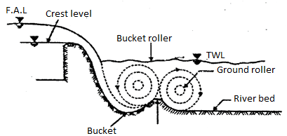
Fig 39: Bucket type energy dissipater

Fig 40: Hydraulic jump type energy dissipater
- Due to heavy turbulence, it is essential to produce hard floor. For hydraulic jump sloping glacis are preferred to a horizontal bed and jump is made to occur on the glacis only.
- In bucket type energy dissipaters flow of water is directed into air and thus fall occurred away from toe of dam. These are suitable under any conditions of tail water provided good hard rock is available. These are more economical than hydraulic jump type.
- The energy is destroyed by a creation of jet and impact of water on the bed of river and scouring takes place which is small and away from toe.
Energy Dissipation through Buckets:
- If the depth of tail water is much large and due to this there is a formation of hydraulic jump, then in such situation, bucket type deflectors may be used to dissipate the energy. These buckets are submerged buckets.
Types of buckets
Buckets are mainly classified into three types:
- Solid roller bucket
- Slotted roller bucket
- Ski-jump bucket
Solid roller bucket
- This type of bucket consists of a concave circular apron of large radius and a deflector lip. Fig. shows solid roller bucket.
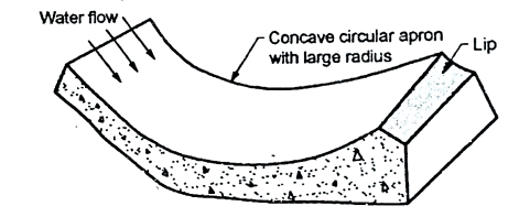
Fig 41: Solid roller bucket
- When water flows over the solid roller bucket, then complete sheet of water leaving the bucket is jumped upward by the bucket lip and two elliptical rollers are developed as shown in Fig.
- Two elliptical rollers move in clockwise direction and anticlockwise direction.
- Definition: The bucket rollers developed on the surface of roller moves in anticlockwise direction known as bucket roller or surface roller.
- Definition: The other bucket rollers developed on the ground surface moves in the clockwise direction called as ground rollers.
- It is shown in Fig.
- The movement of this roller along with the intermingling of the incoming flows causes the dissipation of energy.
Slotted roller bucket
- A slotted roller bucket consists of concave circular apron having large radius; like solid circular bucket, only difference is that it has slotted deflector lip as shown in Fig.
- In such type of bucket also two rollers are developed as developed in solid roller bucket. But in this type water leaves lip of the bucket at a flatter angle and only a part of it gets jumped upwards.
- In this case, less violent ground roller occurs which makes the smoother flow on d/s side.
- The slotted roller buckets are suitable only for a limited range of tail water depth because excessive large jet of water leaving lip get depressed and drive to the river bed which will scour the bed. Fig. Shows hydraulic action in slotted roller bucket.
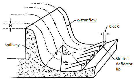
Fig 42: Slotted roller bucket
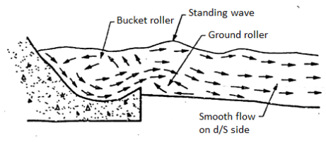
Fig 43: Hydraulic behavior in a slotted roller bucket
Ski-jump bucket
- When tail water depth is less, then in such case a ski-jump bucket can be used. In such bucket the lip of the bucket is shaped in such way that the complete sheet of water flowing over the bucket is jumped or deflected as a free jet. This free jet further falls back into the river at a safe distance away from the spillway.
- Ski-jump bucket dissipates the energy by air resistance, breaking up of the jet into bubbles and impact of falling jet.
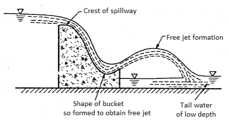
Fig 44: Ski jump bucket
- Various agencies have developed the various types of stilling basin and the designs of stilling basin have been innovated on the basis of long experience in dam construction field and experiment on various model with a basic view of protection and economy.
- Stilling basins are concrete apron provided with auxiliary devices like chute blocks, battle walls sills, dentated sills etc. All these devices can useful in dissipating the energy of water flow by offering resistance to flow and thus stabilize the flow within shorter length of the basin and hence achieve the economy.
Definition of stilling basin:
- Definition: A structure built with the auxillary devices on the downstream side which dissipates the energy of water flow by offering resistance is called stilling basin.
- Definition: If the hydraulic jump is basically used for dissipating the energy, then structure is called as hydraulic jump type of stilling basin.
- The auxillary devices can also be used for controlling the jump.
Effects produced by auxiliary devices
Chute blocks
- Chute blocks are the row of small projections look like the teeth of saw. These blocks are provided at the entrance of the stilling basin.
- When the flow over the spillway comes towards the stilling basin then chute blocks lifts some part of flow and hence produces a shorter length of the jump which is not possible without chute blocks. Chute blocks also help in stabilizing the flow and finally improve the jump performance. See Fig.
Battle Piers or friction blocks
- Battle piers are the blocks which are located within the basin across the basin floor.
- Theses piers break the flow of water and dissipate energy developed by impact. These piers are suitable for low spillway or weirs and unsuitable for large spillway due to cavitation’s.
End sills and dentated sills
- At the end of the stilling basin, sill or sometimes dentated sills is generally provided, which diffuses the residual portion of high velocity jet flowing at the end of basin. See Fig.
- Various Agencies has standardised stilling basin for different ranges of Froude numbers.
- Hence according recommendation of Agencies, they have made the categories of standard stilling basin as follows:
- Stilling basin type I, II, III and IV (I.S.I. Standardised basin, IS 4997-1968) L.S.A. Is Indian Standard Institution.
- U.S.B.R. Stilling basin II
- U.S.B.R. Stilling basin IV.
Stilling Basin type I, II, III and IV (IS: 4997-1968)
- I.S.I. Standardised the basin in four types. Type I and II are used for Froude number less than 4.5 with horizontal apron and type II and IV are used for Froude number more than 4.5 with sloping apron.
Hydraulic jump type stilling basin with horizontal apron
- Hydraulic jump type stilling basin with horizontal apron is more suitable and provides best solution for energy dissipation, when the tail water rating curve nearly follows the hydraulic jump curves.
- Hydraulic jump type stilling basins are recommended for spillway having weak bed conditions, end weirs and barrages on sand and gravel. Froude number (F) is given by the following equation: F = V /√9D
1. Stilling basin type I
- F<4.5 and this type of basin is generally encountered on weirs and barrages. The various factors involved in the design of stilling base type I are as follows:
1) Elevation of basin floor
2) Basin length and depth
3) Basin appurtenances for basin type
- Chute blocks
- Basin blocks
- End sill or Dentated sill
- Basin appurtenances are chute blocks, basin blocks and end sill. Fig. Shows the stilling base type 1.
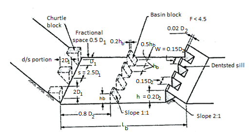
Fig 45: Stilling basin type 1, F<4.5
1) Elevation of basin floor
Consider HL =Head loss in hydraulic jump,
q= Discharge intensity
D₁ = Width of chute block as shown in Fig
D₂ =Width of end sill.
S = Spacing
By knowing the value of HL and q, Dc, D₁ and D₂ can be determined from the following formulae.


Dc, D1, and D₂ can also be determined from Fig.
The curve as shown in Fig. Is used to determine sequent depth (i.e., De, D1, and D₂).
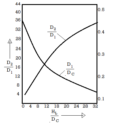
Fig 46: Graph of HL/Dc  H2/D1
H2/D1
2) Basin length and depth
- Let, Lb= Length of the basin can be obtained from the curve given in Fig.
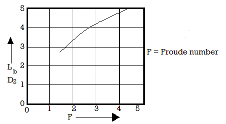
Fig 47: Recommended length for stilling basin type 1
- End sill is provided to the basin. Note that the basin floor level should be taken raised above the level required from the consideration of sequent depth.
- Because of site condition, the rise of the floor becomes critical, then in such cases, chute blocks and basin blocks are provided.
- If the velocity of flow at the location of basin blocks is more than 15 m/s, basin blocks should not be used and floor or basin should be kept at a depth equal to D₂ below the tail water level. The tail water depth should not be more than 10% of D₂.
3) Basin appurtenances for basin type I
- Following are the various basin appurtenance:
(a) Chute blocks
- Height of chute blocks should be equal to 2D1 on the glacis slope and its top length should also be equal to 2D1 width of the chute blocks should be equal to D1 and its spacing is equal to 2.5 D1.
(b) Basin blocks
- The height of the basin blocks in form of D1 can be determined from curve obtained by the graph of froud number (F) versus
 The width and spacing of the basin blocks should be equal to its height.
 - The u/s face of the basin blocks should be adjusted at a distance of 0.8 D₂ from d/s face of the chute blocks.
(c) End sill or Dentated sill
- Recommended height of dentated sill is 0.2 D₂.
- The maximum width and dents spacing should be according to Fig.
2. Stilling basin type II
Fig. Shows a stilling basin type II.
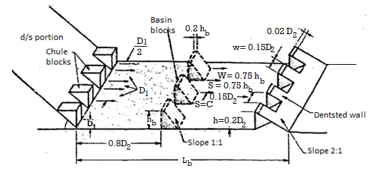
Fig:5.48
- It involves the following components.
- Elevation of basin floor
- Basin length and depth
- Basin appurtenances
- Chute blocks
- Basin blocks
- End sill
(i) Elevation of basin floor
- Same procedure of stilling basin type I is used to determine elevation of basin floor.
(ii) Basin length and depth
- The length of the basin is determined from curve of graph of Froud number (F)
 versus Where Lb is the length of the basin. Maximum rise or depth of the basin floor should not be more than 15% of D2 and in such case, basin blocks are provided.
 - The basin should be provided with end sill and chute blocks. If the velocity of flow at the location of basic blocks is more than 15 m/s, basin blocks are not recommended to provide and, in such situation, the floor of the basin should be at a depth equal to D₂ below tail water level.
(iii) Basin Appurtenances
(a) Chute blocks
- The height, spacing and width of chute blocks should be equal to D₁.
- Note that width and spacing can be changed so as to eliminate the frictional blocks.
(b) Basin blocks
- The height of the basin blocks in terms of D1 can be obtained from the curve of graph of Froud number versus D₁
(c)End sill
- Recommendation of end sill is as same as type I.
Hydraulic Jump type stilling basin with sloping apron
- Stilling basin of type III and type IV is of hydraulic jump type stilling basin with sloping apron.
3. U.S.B.R. Stilling basin II
- U.S.B.R. Recommended for basin II for large structure like dam spillway, large canal structures etc. when Froude number (F) is more than 4.5 i.e., F> 4.5, then U.S.B.R. Stilling basin II are provided.
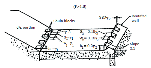
Fig 49: Details of U.S.B.R stilling basin 2 (F>4.5)
- The length of the basin according to the Froude number are given in the following table.
Sr.no | F | Length of Basin |
1 | 4 | 3.6y2 |
2 | 6 | 4y2 |
3 | 8 | 4.2y2 |
4 | 10 or more than 10 | 4.3y2 |
- Various dimensions of chute blocks, dentated sill, slope, dentated wall etc. are shown in Fig.
4. U.S.B.R. Stilling basin IV
- Fig. Shows various details of U.S.B.R. Stilling basin IV. This type of basin IV is used for the Froude number between 2.5 and 4.5 which normally occurs in canal weirs, canal fall.
- Note that only rectangular cross section of a basin is applicable in such type II.
- If there is a formation of oscillating waves within the range of Froude number i.e., 2.5 to 4.5, then they can be controlled by providing large chute blocks.
- The floor of the basin can be made at such a level as to provide 5% to 10% more water depth than the theoretical y₁.

Fig 50: Details of U.S.B.R stilling basin (Froude number is in between 2.5 to 4.5)
- Definition: These are also called as crest gates. The gates which are provided at the crest of spillway are called as crest gate or spillway gates.
- There are different types of gates and these are non automatic and automatic.
- These are fitted in steel frames fitted in piers.
Classification of Spillway Crest Gates:
1. Non Automatic Gates
- Vertical lift gate
- Taintor gate/Radial gate
- Flash board
- Drum gate
2. Automatic Gate
- Reynold's gate
- Vishweswarya gate
1. Non Automatic Gates:
- The non automatic gates are lifted by an electronic distant control system.
- They are classified as:
a. Vertical lift gate
- These are made of steel sheets fitted on frames.
- These gates are suspended by iron chains or wire rope within frames and guides with rollers to reduce and lifting force.

Fig 51: Vertical lift gate
b. Taintor gate or radial gate
- These are easy to operate and economical. It consists of plate of iron mounted on triangular frame of girder and fitted to an axle.
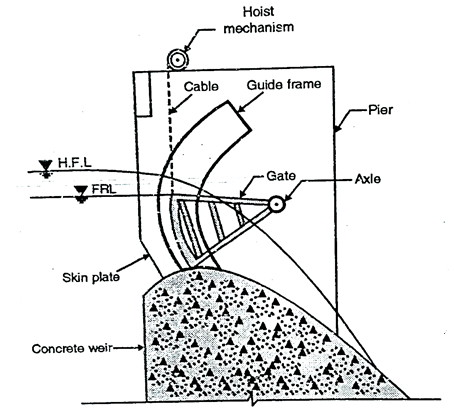
Fig 52: Taintor gate
- The shape is like segment of circle and properly braced steel framework.
- During floods gates are lifted and flood water is allowed to flow towards downstream side from over the crest of spillway.
2. Automatic Gate:
a. Reynold's gate:
- It is fixed roller automatic gate, it moves up and down along vertical face of the spillway.
- The gates are connected to one counter weight by a system of pulley and chains.
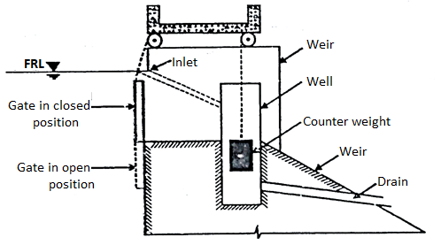
Fig 53: Reynold’s gate
- This counter weight is placed in well and this well is connected to upstream water and when water reaches FTI counter weight get submerged and loses its weight and gates slide down allowing flood to pass over the crest.
b. Vishweswarya gate:
- These are fixed roller type, the eight gates consist of 2 light, 2 heavy gates connected to each other on both sides of master pier.
- A counter weight well is constructed behind each master pier.
- This is connected to reservoir when water enters into this well and when it rises to FRL it reduces weight of counter weight and heavy gate slides down pulling up light gates and creating opening to dispose off flood.
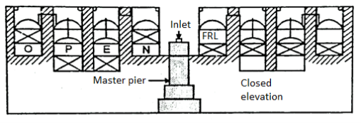
Fig 54: Vishweswarya gate
- Hydro-electric power plants utilize the potential energy of water to move hydraulic turbines which are coupled to electric generators. Therefore, these plants have to be located where the water resources are available in abundance at sufficient head.
- The first hydro power plant was set up in 1897 at Darjeeling of 200 kW capacity and the first major hydro-electric power plant was commissioned in 1902 of 4.5 MW capacity of Sivasamudram scheme in Mysore.
Principle and Operation of Hydro - Electric Power Plants:
- In hydro-electric power plants the energy of water is utilized to move the hydraulic turbines which in turn runs an electric gene to convert the mechanical energy of turbine into electric energy.
- The rain water that flows on the earth's surface has potential energy relative to the ocean towards which it flows. In hydroelectric power plants, the water is collected and artificially stored by constructing dams across the flowing streams.
- This potential energy of water is converted into mechanical work and ultimately into electrical energy. The power developed by the hydraulic turbine depends on the quantity of water and the head of water available.
Input power to a hydraulic turbine is given by the equation,
 (Watt)

Where  = density, Q = discharge and H = available head of water
- The quantity of water available at the selected site depends upon the rainfall and run-off in that area.
- Presently, India generates about 14% of hydro power out of total power generation from all sources.
Advantages and Disadvantages of Hydro Power Plants over other Power Plants:
Advantages:
- Though its capital cost is comparatively high but its operation cost is much less. Due to this the cost of power generation per unit is low.
- These plants are more reliable.
- Starting and stopping of these plants takes very short time compared to steam and nuclear power plants.
- These plants have no ash disposal problems of steam power plants and nuclear waste disposal problems of nuclear power plants.
- The life expectancy is higher It is about 50 years.
- These plants have high efficiency over wide range of loads compared to other power plants.
- These plants can be used both as base load and peak load plants.
- These plants require less supervising staff.
- These plants car. Be used for irrigation and flood control purposes in addition to power generation.
- It does not require any fuel for power generation.
Disadvantages:
- The total power developed depends upon the availability of quantity of water, therefore, these are dependent on rainfall.
- These plants are usually located far away from load centres, hence, it requires long transmission lines. It increases the cost of transmission lines and power loss.
- Time required for development of such plants is high.
- Hydroelectric plants need high capital cost and their selection is based on availability of water. It disturbs the ecology of the area.
- India is the 7th largest producer of hydroelectric power in the world. It was producing 114 TWh of energy in the year 2008 which is about 3.5% of the world's total hydroelectric power.
- Present installed capacity of hydroelectric power is 41632 MW as on 30 April 2015 which is about 15.5% of total power generation in India.
- India has hydropower potential of about 84000 MW at 60% load factor which can be economically exploited. It is equivalent to 600 thousand million kWh (TWh/year).
- Table shows the river system and hydropower potential and possible number of schemes in India.
Sr. No. | Group of Rivers | Hydropower potential (MW) | Possible number of Schemes |
1 | Brahmaputra | 34920 | 226 |
2 | Great Indus | 19998 | 190 |
3 | Ganga | 10715 | 142 |
4 | East flowing rivers in south India | 9532 | 140 |
5 | West flowing rivers in South India | 6149 | 94 |
6 | Rivers in central India | 2740 | 33 |
| Total | 84044 | 845 |
- Region wise the total hydro power potential (84044 MW) is as follows:
North = 30155 MW, East = 5590 MW,
South = 10763 MW
West = 5679 MW and North-East = 31857 MW.
- Apart from above, India (As projected by MNES) has a potential of about 15000 MW of installed capacity from mini, micro and small Hydel power projects.
- Fifty sites of pumped storage plants with total capacity of 94000 MW have been identified.
- Various Government agencies involved in development of hydro power are, NHPC, NEE PCO, THDC, State Electricity Boards (SEB's) along with many agencies in private sector.
- 12th Five Year Plan (2012-2017) has a target of about 30920 MW in Central, state and private sectors. State wise targets are indicated in Table
Sr. No. | State | Capacity (MW) |
1 | Andhra Pradesh | 1560 |
2 | Arunachal Pradesh | 9579 |
3 | Assam | 150 |
4 | Himachal Pradesh | 2457 |
5 | Jammu and Kashmir | 3923 |
6 | Karnataka | 400 |
7 | Kerala | 373 |
8 | Madhya Pradesh | 166 |
9 | Manipur | 1566 |
10 | Meghalaya | 504 |
11 | Punjab | 243 |
12 | Sikkim | 2455 |
13 | Tamil Nadu | 500 |
14 | Uttarakhand | 6858 |
15 | West Bengal | 186 |
| Total | 30920 |
The hydro-electric power plants are generally classified as follows:
1. Plants Based on Availability of Head
- Low Head Plants
- Medium Head Plants
- High Head Plants
- High Head Diversion Plants
2. Plants Based on Type of Loads
- Base load plants
- Peak load plants
3. Plants Based on Quantity of Water Available
- Run-off river plants without pondage
- Run-off river plants with pondage
- Storage type or Valley Dam plants
- Pumped storage peak load plants
- Mini and micro hydel power plants
Plants Based on Availability of Head:
Low Head Plants:
- Hydro power plants are called as low head plants in case the available water head is less than 30 meters. In such plants the water is stored by constructing a dam across a river and the power plant is constructed at the base of the dam on the downstream side.
- The excess water available is allowed to flow over the dam itself. Such plants use Francis, propeller or Kaplan type of hydraulic turbines.
- A low head plant is represented in Fig. In these plants no surge tank is used since the plant is located near the dam itself.

Fig 55: Low head plants
Medium Head Plants:
- Medium head plants are similar to low head plants but they work under a head of 30 m to 100 m. Such a plant is shown in Fig. These plants generally use Francis turbine.

Fig 56: Medium head plant
High Head Plants:
- Hydro power plants are called high head plants in case the available water head is more than 100 meters. In such plants, water is stored at high head due to rain or melting of snow. Water is usually available throughout the year.
- Such plants use Francis turbine upto the head of 300 m and Pelton wheel when head available is more than 300 m.
High Head Diversion Plants:
- These plants develop high heads by diversion of water.
- It can be achieved in the following ways:
- By a system of channels and tunnels to another nearby river which is at a much lower level e.g., Beas Sutlej link project. In this project the water of river Beas is directed to river Sutlej through a power house. It develops a head of 320 m and generates 267 MW of power. Another example is the Koyna project in which the water of Koyna river is diverted into Vitrani river and it develops a head of 420 m.
- Another method of high head diversion plant is the diversion of water along tunnels from upstream point of a river to downstream point of the same river e.g., the Chenani project built on river Tawi in Jammu and Kashmir.
- The water is diverted through channels, tunnels and conduit from upstream to downstream having total length of about 20 km.
- The main components of a high head diversion plants are:
- Diversion weir
- Intake canal tunnel
- Head rack either open or tunneled
- Surge tank
- Penstock
- Power house
Plants Based on Type of Loads:
Base load plants:
- These type of hydro power plant can take up load on base portion of load curve of the power system. These plants are generally of large capacity to meet almost the constant load.
- The runoff river and storage type plants are used as base load plants. Load factor for such plants is high.
Peak load plants:
- Hydro power plants used for meeting the top portion of the load curve are called peak load plants.
- Run off river plants with pondage and storage type of hydel plants can be used as peak plants. These plants are required to run for short duration of time when the load becomes more than the base load. The load factor of peak load plants is considerably low as compared to base load plants.
Plants Based on Quantity of Water Available:
Run-off River Plants without Pondage:
- These type of hydro plants do not store water and use the water directly taken from the river. Since there is no control on the availability of water from the river, the power output of such plants fluctuates widely, hence, the utility of these plants is very less compared to other plants.
- These plants can only be built on rivers having continuous flow like in Europe.
- These are usually low head plants except in cases where the river has a natural fall. General arrangement of run-off river plant without pondage is shown in Fig.
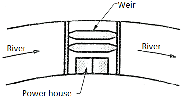
Fig 57: Run-off River plant
Run-off River Plants with Pondage:
- The rain water is only available for certain period of time. Due to this run-off is deficient during the large part of the year.
- Thus, to meet the certain power demand, an artificial storage of water is necessary in the form of pondage and storage to meet and regulate the requirement of water during deficient days. It helps in meeting the power demands.
- A pondage is defined as small pond or reservoir built near the power house to regulate the small quantity of water.
- It meets the water requirement for meeting the hourly changes in power demand.
- While, the storage is built in the form of dam across the river, whose function is to store very large amount of water during excess run-off period (rainy days) and supply this water during the deficient period of run-off.
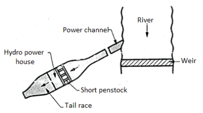
Fig 58: Power house with pondage
- Thus, the storage increases the plant capacity to generate more power. The storage capacity of dam can be determined with the help of hydrographs or mass duration curves.
- The power house with pondage is shown in Fig. The pondage regulates the variable water flow to meet the power demand.
- It is required to meet the shorter fluctuation of water requirement to cater the requirements of:
- Sudden small changes in load on power plant.
- Sudden changes in inflow of water.
- The pondage is located at suitable site near the power house as shown in Fig.
- A weir is provided across the river and water from the river is directed through the water channel to pondage and to the power house through small penstock (water feeding pipes).
Storage type or Valley Dam Plants:
- Storage type plants are constructed if the rainfall occurs only for few months in a year and the remainder period are dry as in case of our country.
- In such plants a large amount of water is stored in a reservoir behind a dam and it is made available to power plant with controls on required basis.
- These plants can be used both as base load as well as peak load plants. Fig. Shows the location of storage reservoir. It is built across the dam to store huge quantity of water.
- It increases the capacity of river from 6 months to 2 years depending on its size while the pondage increases the capacity of river for a very short time.
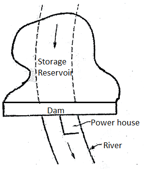
Fig 59: Storage reservoir with power house
Pumped Storage Peak Load Plants:
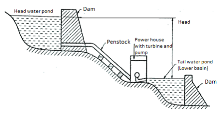
Fig 60: Pumped storage peak load plant
- These types of plants are suitable as peak load plants at locations where there is a storage of water since these plans are designed such that it pumps back a portion of its water. Supply from tail race to head race during non-peak periods The arrangement for such plants is shown in Fig.
- The power for running the pumps for pumping of water back is supplied with secondary power from other plants such as steam a nuclear plants or run-off river plants.
- Such plants work in conjunction with steam power plants and it improve the overall thermal efficiency of the combined power plant since the efficiency of thermal power plants is poor at part loads.
- Recently several successful pumped storage plants have been constructed with reversible pump turbines.
- Such a unit acts as a turbine to develop power when rotating in one direction and the same unit acts as a pump when it rotates in reversed direction.
- In these plants very little water is required for its operation compared to other types of hydro power plants since the additional water is only required to take care of seepage and evaporation from the storage reservoir.
Advantages of pumped storage plants:
- Increases the peak load capacity of plant with low capital cost.
- The efficiency of the plant increases.
- It improves the load factor (i.e., ratio of average load to maximum demand)
- Provides better and uniform management of loads with less dependence on stream flow conditions.
Mini and Micro Hydel Power Plants:
- In order to meet the present power crisis upto a certain extent, mini and micro hydel power plants can be built along a stream of river in our country.
- Mini power plants work in the range of 5 to 20 m head while the micro hydel plants work under a head less than 5 m.
- Such low head mini hydel plants in our country have not been explored except in the states of U.P., H.P. And Arunachal Pradesh since the capital cost per kW is high.
- It is estimated that the potential of these mini plants scattered all over the country may be as much as 20000 kW.
- These plants in small capacity can easily be constructed in a much shorter time compared to other hydro plants which requires few years for their construction.
- Mini hydel plants use special type of turbine called bulb type turbines.
- In these turbines the scroll casing has been modified in the form of horizontal tapering duct with the flow passage forming a sort of throat where the turbine runner is located.
- The draft tube of the turbine is replaced by a straight diverging tube. Such a system reduces the hydraulic losses.
- In order to reduce the cost of micro hydel power plants, it is necessary that such plants are designs in such a manner that they fit on the existing structures like channels for irrigation, locks, small dams.
- It reduces the cost and time for their construction work. These plants are designed in such a way that their operation is automatically controlled so as to reduce the man power.
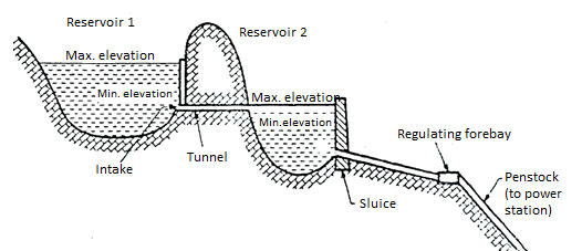
Fig: 61
Canal
- It is an open waterway excavated in natural ground following its contour with slight slope corresponding to head loss due to friction.
Flume
- It is an open channel constructed on a surface above the ground supported on trestle (tars fixed on pair of legs for support).
Tunnel
- A tunnel is a closed conduit which is constructed if there exists a ridge or mountain between the dam and power house. It allows water to enter into the turbine.
- Tunnels are also constructed for supply of water from one reservoir to another reservoir.
Pipe line
- Pipe line is a closed conduit supported on or above the ground surface.
Penstock
- Penstock is a close conduit to carry water from dam to the turbine.
Hydraulic turbines are classified based on the energy available at the inlet of turbine, the availability of head, direction flow over the vanes in the runner and its specific speed. Following is the important classification of turbines.
Classification of Hydraulic Turbines:
1. According to the type of energy available at inlet to the turbine
- Impulse turbine
- Reaction turbines
2. According to direction of flow though runner
- Tangential flow turbines
- Radial flow turbines
- Axial flow turbines
- Mixed flow turbines
3. According to the head available at inlet to the turbine
4. According to the specific speed (Ns) of the turbine
5. According to discharge
6. According to speed of runner
7. According to power output, Ps
1. According to the type of energy available at inlet to the turbine
a. Impulse turbine
- An Impulse turbine, as the name suggests, works on the principle of impulse.
- In these turbines, the head or pressure energy of water is first converted into kinetic energy by means of a nozzle or set of nozzles kept close to the runner.
- This high velocity jet produced by nozzle is allowed to impinge on the set of buckets fixed on the outer periphery of the wheel or runner. The direction of jet is changed by buckets. The change of momentum of water causes the wheel to rotate, thus produces mechanical energy.
- It should be noted that pressure of water is atmospheric and remains constant while passing; over the runner.
- Examples of important impulse turbines are Pelton wheel, Girard turbine, Turgo turbine etc.
b. Reaction turbines
- In these turbines, a part of pressure energy is first converted into kinetic energy before supplied to runner.
- Turbine to run in closed passages which are completely filled with supplied to runner. Therefore, the water enters the runner having partly the pressure energy and partly the kinetic energy and both these energies are reduced simultaneously while passing over the runner and produce mechanical energy. Hence, these turbines work on the principle of impulse-reaction.
- The runner of these turbines being under pressure above atmospheric, it requires the blades of turbine to run is closed passages which are completely filled with water in all conditions.
- Examples of reaction turbine are Francis, Kaplan and Propeller turbines.
2. According to direction of flow though runner
a. Tangential flow turbines
- It is the turbine in which water flows tangent to the runner.
b. Radial flow turbines
- It is the turbine in which the water flows in the radial direction through the inner
c. Axial flow turbines
- It is the turbine in which the water flows through the run along the direction parallel to the axis of rotation of runt r
d. Mixed flow turbines
- It is the turbine in which water flows in the runner i radial direction but leaves in axial direction.
3. According to the head available at inlet to the turbine
- Low head turbines (2 m to 15 m)
- Medium Lead turbines (16 m to 70 m)
- High head turbines (71 m and above)
4. According to the specific speed (Ns) of the turbine
- Low specific speed.
- Medium specific speed.
- High specific speed.
5. According to discharge
- Turbines can be classified based on low discharge (Pelton turbine), medium discharge (Francis turbine) and high discharge (Kaplan turbine).
6. According to speed of runner
- Turbines are generally not specified based on speeds because turbines are directly coupled to generator. The generator speed is given by.
N = (120 f)/P
Where, f = frequency of generation in het
p= No of poles of the generator
- For above reason, the turbines are classified based on their specific speed and not on their actual speeds which is equal to generator speed irrespective of power output.
7. According to power output, Ps

Where,  = 1000 g/m3 and g = 9.81 m/s²
- Therefore, power output depends on discharge (Q) in m3/s and head (H) in meters.
- Maximum power developed by one unit of turbines are as follows:
- Impulse turbine 250 MW
- Francis turbine = 710 MW
- Kaplan turbine = 110 MW
- Obviously for large power generation the Francis turbine is the first choice depending upon the availability head and discharge.
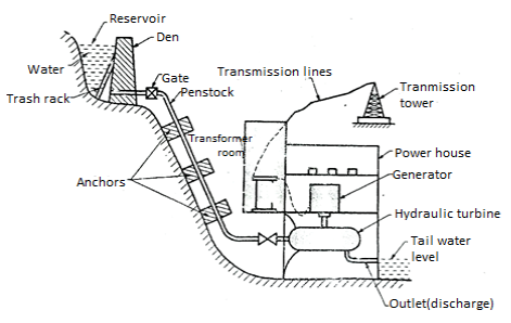
Fig5.62: Schematic layout of Hydro-electric power plant
- A large amount of water is collected during rainy season in a reservoir behind a dam. In case the rainfall is low in a particular year the low head of the reservoir will not be able to meet the maximum load, therefore, the present trend is to use hydro-electric power plant with steam power plant in an interconnected system.
- The main components of the hydro-electric power plant and their functions are as follows:
- Reservoir.
- Dam
- Trash rack
- Gate
- Forebays
- Surge tank
- Waterway and penstock
- Spillway
- Power house
- Hydraulic turbines
- Draft tube
- Tail race
Reservoir:
- A reservoir is provided to store water during rainy season and supplies the same in dry season. The water from the reservoir is used to run the hydraulic turbine.
Dam:
- A dam is structure of considerable height built across the river. Its function is to provide working head of water for power plant and to increase the storage-capacity of reservoir.
Trash rack:
- These are made up of steel bars. Trash rack is provided to prevent entry of debris into the intakes from dam or from the forebays. Any debris into the intake water pipe may damage the turbine runners or choke the nozzles of an impulse turbine.
Gate:
- The gate is provided for controlling of flow of water from reservoir to hydraulic turbine through penstock. It is closed when maintenance of system is required.
Forebays:
- It is small water reservoir at the end of water passage from the reservoir and before the water is fed to the turbine to the penstock as shown in Fig.

Fig 63: Forebay
- It acts as a temporary regulating reservoir. It stores water when the load on the plant reduces and the same water is supplied to the turbine at the time of increasing load in the initial stages. It helps in absorbing the flow variations.
Surge tank:
- In case the load on the turbine suddenly decreases, the gates admitting water to the turbine are suddenly closed due to governor action. As a result, it reduces the water flow with sudden increase of pressures in the penstock. This sudden rise of pressure in penstock is called "Water Hammer".
- On the other hand, due to sudden increased load on the turbine, the gates admitting water to the turbine are suddenly opened. It causes water to rush from penstock into the turbine and it creates a vacuum in the penstock.
- Therefore, penstock is subjected to positive pressure (water hammer) due to sudden decrease in load on the turbine and to negative pressure due to sudden increase in load on the turbine.

Fig 64: Surge tank
- In order to provide better regulation of water pressure in the system, a surge tank is used which is located near the power house on high ground. When the turbine rates are closed and water flow to the turbine reduces, the water rises into the surge tank It produces a retarding head with reduced velocity of water in the penstock. As soon as the velocity of water in the penstock is reduced to a value corresponding to the level of the turbine, the level of water in the surge tank starts falling and fluctuate up and down until its motion is damped out by friction.
- Similarly, during the increase load on the turbine, additional water flows from the surge tank to the turbine. It produces an accelerating head which increases the velocity of flow of water in the penstock.
- Therefore, a surge tank helps in establishing the velocity and pressure in the penstock and it reduces the water hammer effect.
Waterway and penstock:
- A waterway is used to carry water from the dam to the power house. It includes canal and penstock (closed pipe) or a tunnel. The penstocks are made up of steel of reinforced concrete which are designed to withstand high pressures. Penstocks are supported by anchors. Sharp bends in penstocks are avoided in order to reduce the hydraulic losses.
Spillway:
- A spillway is provided to discharge the flood water and to keep the level of water below the designed maximum level in the reservoir. Thus, a spillway saves the dam from damage during floods.
Power house:
- A power house consists of hydraulic and electric equipment’s where the water energy is converted into electrical energy. Usually, the power house is located underground whenever possible e.g., as in case of Koyana power house in Maharashtra state.
Hydraulic turbines:
- These are used to convert the kinetic energy of water into mechanical energy.
Draft tube:
- A draft tube is a passage which connects the exit from the turbine runner down to tail race water level.
- It supplements the action of runner of the reaction turbine by utilizing the remainder K.E. Of the water at discharge end of the runner. Another purpose of the draft tube is to permit the setting of the runner of the reaction turbine wheel at a level above that of water in the tail race under high water and flood conditions of the river.
Tail race:
- A tail race is a water way to lead the water discharged from the turbine to the river.
References:
- Fundamental of Hydraulic Engineering System by Houghalen, Pearson Publication.
- Irrigation and water Power engineering by B.C. Punmia, Laxmi Publications.
- Engineering Hydrology by K. Subramanya, TMH.
- Irrigation Water Power and Water Resource Engg. By K.R. Arora.
- Water resource engineering by Ralph A. Wurbs & Wesley P. James, Pearson Publication.