Unit - 2
Fluid Statics
Liquid pressure can be calculated using the following relationships.
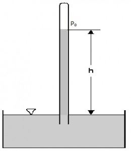
Fig no 1Fluid measurement
Pfluid = P + ρgh
Where,
P = Pressure on the reference area
P fluid is the pressure at a point in a fluid
ρ is the density of the fluid
g acceleration due to gravity (considering earth g = 9.8 m / s)
h height from the reference point
The volume of this liquid can be calculated by dividing the volume of the liquid by considering the volume of the extracted liquid.
ρ = m / v
Where,
m the size of the liquid
v is the amount of liquid considered
When the liquid is under atmospheric pressure there is a total systemic pressure provided by
Pfluid = Po + ρgh
Where,
Po atmospheric pressure
Conditions for Consideration of fluid pressure:
Water pressure is considered in two cases:
The pressure of the liquid given above is static fluid pressure or hydrostatic pressure. The pressure here is considered to be based on the depth of the liquid only because the pressure generated as a result of the flow of the liquid can be considered minimal. The intensity of static fluid does not depend on the surface area, the composition of the liquid container or the total volume and volume of the liquid.
Remember that here, liquid refers to anything that has the ability to flow. Therefore, this refers to both beverages and gases.
Factors Affecting Fluid Pressure
There are two factors that affect liquid pressure. These two factors are the depth of the liquid and the quantity of it.
Examples:
Q.1 Barometric reading at a place is 75 cm of Hg. Express the pressure intensity of 10 N per cm² is:
(1) m of water
(2) mm of mercury
(3) KN.m^2 abs
Soln.:
Given:

 = 10 N/cm² = 100 kN/m².
(i) In m of water,


(ii) In mm of mercury


(iii) In kN/m absolute,


Absolute pressure,

Q.2 A gauge on suction side of pump shows a negative pressure of 0.285 bar. Express this pressure in terms of
1. Pressure intensity kPa
2. N/m absolute
3. m of water gauge
4. m of oil (S0.85) absolute
5. cm of mercury gauge.
Take atmospheric pressure as 76cm of mercury and relative density of mercury as 13.6.
Soln:
1 bar = 10'^5 Pa
Gauge vacuum reading

Absolute pressure


Equivalent head of water (gauge)


Equivalent head of oil (absolute)

Head of mercury (gauge)


Q.3 A cylinder contains a fluid at a gauge pressure of 350kPa. Express the pressure in terms of the column height of (a) water (o 1000kg/m) (b) Hg (S= 13.6). What would be absolute pressure in the cylinder if the atmospheric pressure is 101.3kPa?
Soln.:
Given:

(a) Pressure in term column head of water,


(b) Pressure head in terms of Hg

(c) Absolute Pressure

Q.4 Mass density of a liquid varies as p = (1000+ 0.008 h). Where 'h' is depth (m) below free surface of liquid. Determine depth at which gauge pressure would be 100 kPa.
Soln.:
Given: 
To find: Depth?
Pressure at any point


Q. 5 Measurements of pressure at the base and top of a mountain are 74cm and 60cm of mercury respectively. Workout the height of mountain if air has specific weight 11.97 N/m²
Soln.:
Pressure at top

Pressure at bottom


Key takeaways:
The pressure of the liquid given above is the constant pressure of water or hydrostatic pressure. The pressure here is considered to be based solely on the depth of the liquid because the pressure generated by the flow of the liquid can be considered minimal. The size of the static fluid does not depend on the surface area, the composition of the liquid container or the total volume and volume of the liquid.
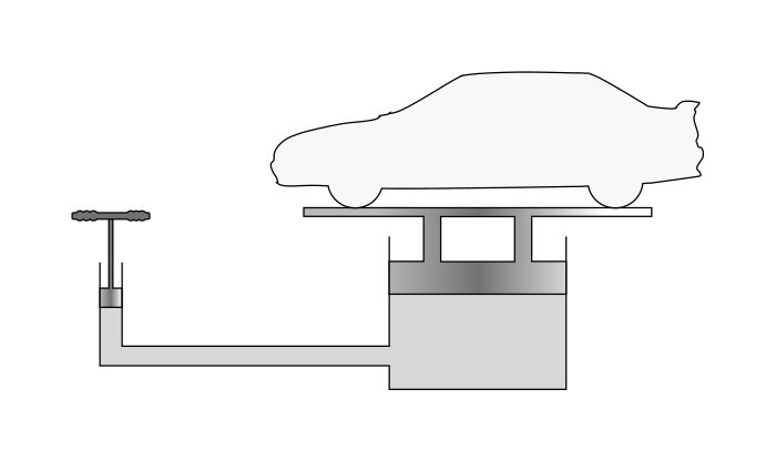
Fig no 2 Pascal's law is the principal behind hydraulic lifting and pressing device

Fig no 3Pascal law applies for fluid
Pascal's law is defined as
This principle is mathematically defined as:
∆p = ρ g ∆ h
Where
∆p hydrostatic pressure (given by pascals in the SI system), or the difference in pressure in two places within a liquid column, due to the weight of the liquid;
ρ the size of the water (per kilogram per cubic meter in the SI system);
g acceleration due to gravity (usually coastal acceleration due to gravity, meters per second);
∆h the height of the liquid above the measuring point, or the difference in height between two points within a column of water (in meters)
Key takeaways:
In this we can find equality
P1 /T1 = P2 /T2
Where:
P1 is the initial pressure
T1 is the initial temperature
P2 is the final pressure
T2 is the last heat
All temperatures were measured in Kelvin's temperature.
Key takeaways:
Tips for flying at very high altitudes
Key takeaways
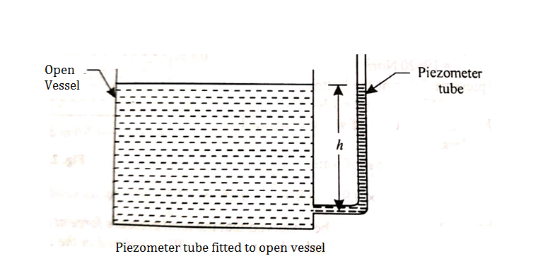
Fig no 4 Piezometer tube fitted to open vessel
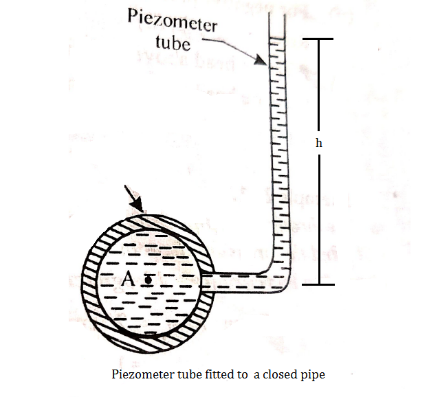
Fig no 5 Piezometer tube fitted to a closed pipe
Key takeaways
Examples:
Q.1 A piezo meter tube is fitted to a tank containing water at a point 600 mm above the tank. The liquid in the manometer is carbon bi Sulphide having a specific gravity of 1.9. Find the height of the free water surface above the bottom of the tank if the piezo meter reading 700 mm. Find also the pressure intensity at the bottom of the tank. Dec. 2005, 4 Marks
Soln.:
Pressure at end of piezometer

Height of water above point A


Height of free surface above bottom of tank
H = h +0.6
= 1.33 +0.6 = 1.93m
Pressure at bottom of tank

Q.2 A piezometer tube is fitted to a tank containing water at a point 500 mm above the bottom of the tank. The liquid in the manometer is carbon tetrachloride (sp. gr. 1.6). Find the height of the free water surface above the bottom of the tank if the piezometer reading is 600 mm. Find the pressure intensity at the bottom of the tank.
Soln.:
For static equilibrium
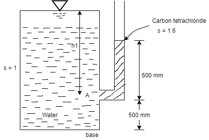
Pressure in the tank at point A= pressure due to piezometric liquid at A


Total height of the free water surface above bottom of tank
h =h₁+0.5 = 0.96 + 0.5 = 1.46 m
Pressure intensity at the bottom of the tank

(a). (b)
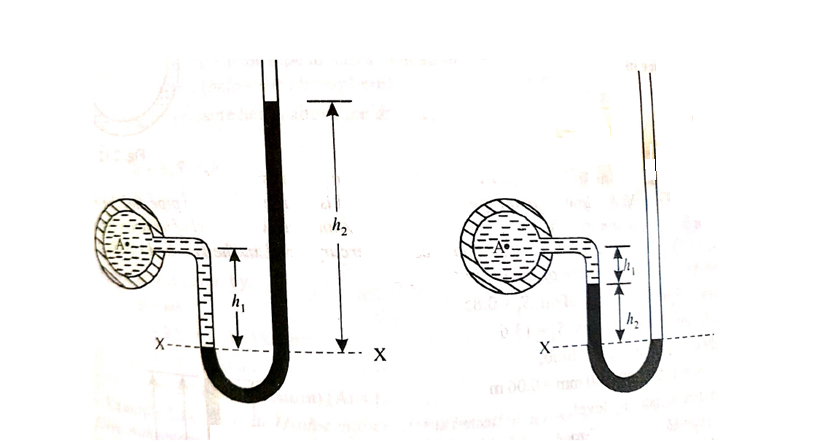
Fig no 6 Utube manometer
Let A be the point at which pressure is to be measured. X-X is the datum line as shown in Fig(a)
Let, h1 = height of the light liquid in the left limb above the datum line
h2 = height of the heavy liquid in the right limb above the datum line
h = pressure in pipe, expressed in terms of head
S1 = specific gravity of the light liquid, and
S2 = specific gravity of the heavy liquid
The pressure in the left limb and right limb above the datum line X-X are equal.
Pressure head above X-X line in the left limb = h+h1S1
Pressure head above X-X in the right limb = h2S2
Equating these two pressures, we get
For negative pressure:
Refer to fig(b)
Pressure head above x-x in the left limb=
Pressure head above x-x in the right limb = 0
Equating these two pressures, we get
h + h1S1 + h2S2 = 0 or h = - h2S2 - h1S1
Examples:
Q.1 A simple U-tube manometer is used to measure water pressure in pipe line. The left limb of manometer connected to the pipe and the night limb is open to atmosphere. The mercury level in the left limb is 80mm below the center of the pipe and the level in the right limb in 220mm above the center of the pipe. Calculate the pressure of water in meter and also in km
Soln.:
Oil


Mercury

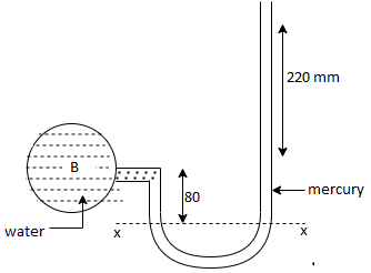


Pressure in the left limb about xx = Pressure in the right limb about x-s


Q.3 A U-tube manometer is used to measure the pressure of water in a pipe line, which is in excess of atmospheric pressure. The night limb of the manometer contains mercury and is open to atmosphere. The contact between water and mercury is in the left limb. Determine the pressure of water in the main line, if the difference in level of mercury in the limbs of U-tule 12 cm and the free surface of mercury is in level with the centre of the pipe. It the pressure of water in pipe he is reduced to 9810 N/m². Calculate the new difference in the level of mercury March 2010,7 Marks
Soln.:

Case I
Given:
h1,=h₂= 12cm=0.12 m.
S2=13.6
Pressure in pipe


Case II
Since the pressure in the pipe is reduced to 9.81 kN/m² (which is less than 14.83 kN/m²), the mercury in the left limp will be rise. Rise of mercury in the left limb will be equal to the fall of mercury in right limb as the total volume of mercury remains same.
Let x = rise of mercury in left limb= fall in mercury in right limb,
Pressure at new section x₁ - x₁


.. New difference of mercury

Q.4 Fig. P shows a conical vessel having its outlet at A to which a U-tube manometer is connected. The reading of the manometer given in the Fig. P. 3.7.15 shows when the vessel is empty. Find the reading of the manometer when the vessel is completely filled with water.
Soln. :

Case I:
Vessel is empty
Pressure in left limb about x-x= Pressure in right limb about x-x


Case II: Vessel is full of water
When pressure is full of water, the pressure in right limb will increase and mercury level will fall by 'y' m, similarly Hg level in left limb will rise by 'y' m
Now consider 7-7 as a datum
Pressure in left limb = Pressure in right limb about z-z


:. Difference of mercury level when the vessel is full of

Key takeaways:
This type of manometer is useful for the measurement of small pressures and is more sensitive than the vertical tube type.
Due to inclination the distance moved by the heavy liquid in the right limb is more.
l = length of the heavy liquid moved in right limb,
Alpha = inclination of right limb horizontal, and
h2 = vertical rise of liquid in right limb from x-x = l sin
h = l sin alpha × S2 - h1S1
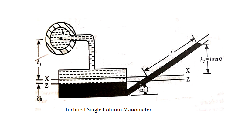
Fig no 7 Single column manometer
Key takeaways
A U-tube differential manometer is shown in fig.
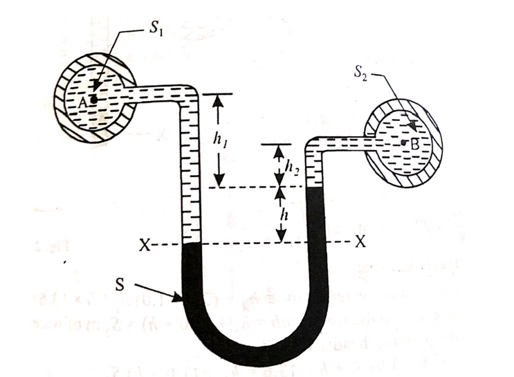
Fig no 8 Utube differential manometer
Let, h = difference of mercury level (heavy liquid) in the U-tube,
h1 = distance of the centre of A, from the mercury level in the left limb
h2 = distance of the centre of B, from the mercury level in the right limb,
S1 = specific gravity of liquid in pipe A,
S2 = specific gravity of liquid in pipe B,
S = specific gravity of heavy liquid o mercury
hA = pressure head at A,
hB = pressure head at B
considering the pressure heads above the datum line x-x, we get
Pressure head in the left limb:
h A + ( h 1 + h ) S1
Pressure head in the right limb:
h B + h 2 × S 2 + h × S
Equating the above pressure heads, we get
h A + ( h1 + h ) S1 = h B + h 2 × S 2 + h× S
( h A - h B ) = h 2 × S 2 + h × S - ( h 1 + h ) S 1
Examples:
Q.1 A differential manometer is connected at two points A and B of two pipes as shown in Fig. Pipe A contains liquid of specific gravity 1.6, while pipe B contains liquid of specific gravity 0.8. If the pressure at A and B are 11.80 x 10 N/m² and 19.60 x 10 N/m2, find the difference in mercury level in the differential manometer.
Soln. :
Pipe A
S₁ = 1.6
PA = 11.8 x 10' N/m² = 118 kN/m² 19.62× 10¹ N/m² = 196.2 kN/m²
h₁ = (2+1,5) = 3.5 h₂ = (1.5 + h)
pipe B
s2= 0.8
h2= 1.5+h
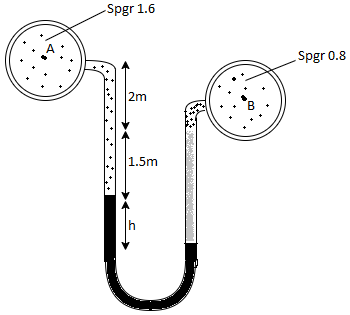
Pressure in left limb = pressure in right limb PA


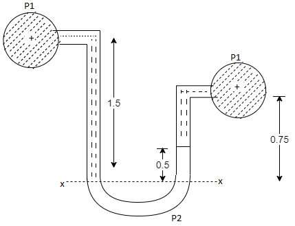
Q.2 A U-tube manometer (Fig. P.) measures the pressure difference between two points A and B in a liquid of density PL The U tube contains mercury of density pa. Calculate the difference of pressure between points A and B in a liquid of density p, The u tube contains mercury of density P Calculate the difference of pressure between points A and B if the liquid contain at A is water take a 1.5 m, b=0.75 m and h= 0.50 m.
Soln.:
Given:


To find :
PA-PB

Pressure in left limb = Pressure in right limb


Q.3 Liquid of specific gravity 1.0 flows through pipes A and B at positive pressures of 0.5 bar and 0.25 bar respectively. Pipe A is 1.8 m higher than B. What would be the difference in the levels of U-tube manometer connected to A and B, having manometric liquid of specific gravity 13.6 ? Liquid level in the limb attached to A is lower than that in the order.
Soln.:
Given:
1 1bar = 10^5 N/m²,
2 P=0.5 bar = 50 kN/m².
3 pB= 0.25 bar 25 kN/m²
Balancing the liquid about x-x in left limb and right limb
Pressure in left limb about x-x= Pressure in right limb about x-x


Key takeaways
(h A - h B ) = h 2 × S 2 + h × S - (h 1 + h ) S 1
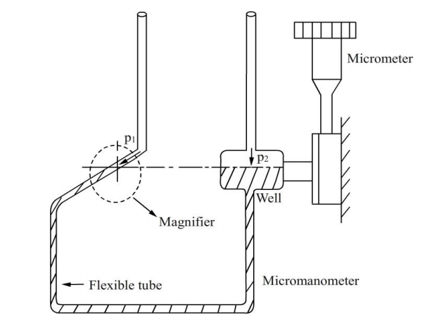
Fig no 9 Micromanometer
Key takeaways
A micro manometer can be used - if required in combination with pitot tubes - to measure, measure, measure and calculate velocity and volumetric flow rate. Micro manometers have high accuracy for measuring high-, low- and variability. Observatory Instruments offer different micro manometers, each with a different application.
Mechanical Gauges
Bourdon tube pressure gauge:

Fig no 10 Bourdon tube pressure gauge
Diaphragm Gauge:
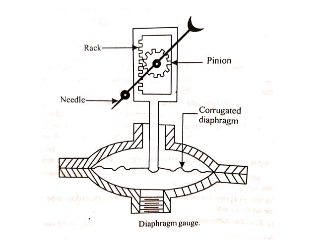
Fig no 11 Diaphragm gauge
Vacuum gauge:
Examples:
Q.1 A pressure gauge, calibrated to read volume of fuel, is used as a fuel gauge. It is connected at the bottom of a fuel tank of area 267 cm². The gauge is calibrated to read maximum volume of 8 liters. If there accumulates 1 cm layer of water in the tank, how much fuel is measured when the gauge shows full scale reading? Assume density of fuel 730 kg/m².
Soln.:
Given:
Tank base Area A = 267 cm² = 267 x 10 m²
Max. volume V = 8 liters = 8 x 10¹ m²
Density of fuel p₁ = 730 kg/m
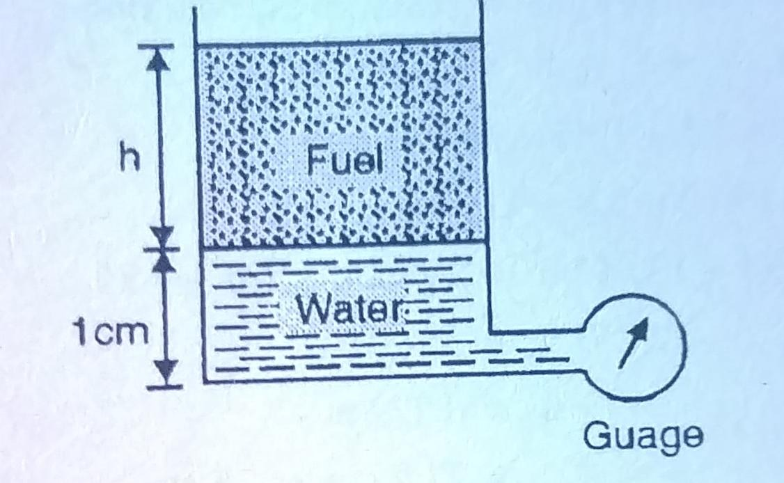
Depth of fuel for maximum volume

Max. Pressure for which gauge is calibrated

Total pressure due to water + Pressure due to fuel


Volume of fuel


For full scale reading, volume of fuel is 7.64 liter
Q.2 Gauge A attached at the bottom of a tank shown in Fig. P. 3.7.7 reads 350 kPa (absolute). What is the height 'h' of water? What is the reading of gauge B?
Soln.:
Given:
P = 350 (absolute)
Pressure due to mercury
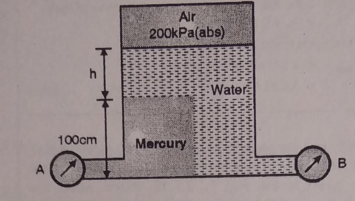

Consider pressure from A up to air
Let 'h' be the height of water


Height of water is 1.69 m
Now consider pressure from air up to gauge B Let P be the gauge pressure at B


Pressure at B is 226.39 kPa (abs)
Q.3 A 6 m deep tank contains 4 m of water and 2 m of oil of relative density 0.8. Determine the pressure at the bottom of the tank.
Soln.:

Specific weight


Q. 4 A closed tank of height 9.0 m is filled with bromine of specific gravity 3.1 to a depth of 2 m and turpentine of specific gravity 0.87 to a depth of 6m. The upper part of the tank contains air under a pressure of 25 kPa (vacuum). Find the absolute pressure at the bottom of the tank in kPa and in cm of mercury Neglect density of air. Consider atmospheric pressure 101.3 kPa
Soln.:
Given:
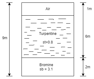
Atmospheric pressure
Patm= 101.3 kpa
Air pressure P=25 kPa (vacuum)
Gauge pressure at bottom of tank
= Air pressure + pressure due to turpentine + pressure due to bromine


Absolute pressure

Pressure head in term mercury

Q. 5 The tank shown in Fig. P. is closed at to and contains air at a pressure of P, Calculate the value of P, for the manometer reading as shown in Fig.
Soln.:
Given:
h₁ = 10 cm = 0.1 m,
h₂ = 150 cm= 15m
h3 = 200+10-150=60 cm=0.6 m

Consider section X-X, balance the fluid about X-X.
Pressure on left limb about XX= Pressure on right limb about X-X


Key takeaways:
There are four type of pressure gauge mainly
1. Mechanical Gauges
2. Bourdon tube pressure gauge:
3. Diaphragm Gauge:
4. Vacuum gauge:
Fluid Statics
Fluid Pressure at a point
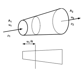
Fig no 12 Hydrostatic force on surface
Pascal's Law of Pressure at a Point

Fig no 13 Pressure at a point
Px = py = pz
Where, px, py and pz pressure point x, y, z respectively.
A typical equation of pressure variability in Static Fluid
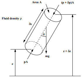
Fig no 14 Pressure variability in static fluid
Dp / d s = -  g cos
g cos 
Vertical Variation of pressure in a fluid under gravity
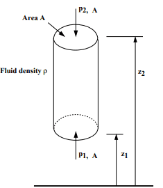
Fig no 15 Vertical Variation of pressure in a fluid
Taking upward as positive, we have
Vertical cylindrical structure of a liquid body = A
Metal size = ρ
The force involved are:
= mass density x volume x g
= ρ.gA.A. (z2 - z1)
Thus in a liquid that is below gravity, the pressure decreases proportionally with the elevation
p2 - p1 = ρgA (z2 - z1)
This is a change in hydrostatic pressure.
Equilibrium of Pressure at Equivalent Static Fluid
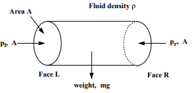
Fig no 16 Pressure act on horizontal surface
Horizontal element of cylindrical cross sectional area = A
Metal size = ρ
Left end pressure = pl
Right end pressure = pr
Equally, the total energy in direction x is zero = pl. A = pr. A
Pl = pr
Therefore, the pressure in the horizontal direction does not change.
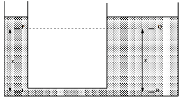
Fig no 17 Pressure in horizontal direction
As we know, P1 = pr
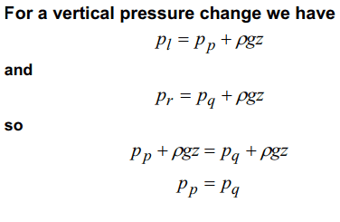
Therefore, the pressure at two equal levels is the same.
Total Hydrostatic Force in the Facial Area
F = p. A
Where p is the same pressure and A is the area.
F = pcg. A
When the pcg pressure is in the center of gravity.
F = γh'A
Where h 'is the depth of the liquid above the centroid of the immersed area.
Examples:
Q.1 A vertical rectangular plane surface has width of 1.5 m and depth of 3.0 m. It is placed in water such that the upper edge is 1 m below free water surface. Find the total pressure and the depth of centre of pressure on the rectangular plane.
Soln.:
Given:
b= 1.5 m,
d = 3.0 m 1m,
s = 1 (water)
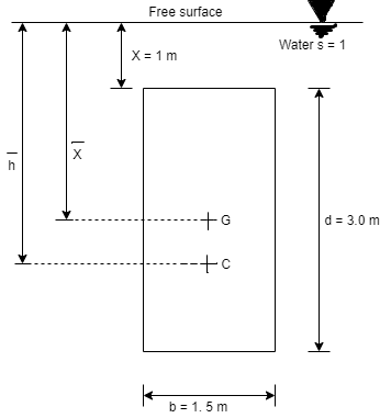
To find: P and h
Area A = b x d=1.5x3=4.5 m²
Distance of centroid of lamina from free surface,

Total of inertia

Total pressure,

Centre of pressure,

Q. 2 A rectangular gate 2 m long and 1.5 m wide lies in a vertical plane with its centre 2.5 m below water surface. Calculate magnitude, direction and location of the total force on the gate. Dec 2011 4 Marks
Soln.:
Given:
x=2.5m, b = 2m, d=1.5m
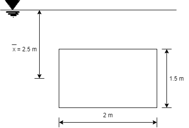
To find
P and h
Moment of inertia

Total pressure

Centre of pressure

Q. 3 An isosceles triangular plate of base band altitude 'h' meter is immersed vertically in water with its apex below the base. The base is parallel to and vertical depth of 'd below free surface. Prove that the depth of pressure is equal to (h²-4dh+6d²)/ (3d+h)
Soln.:
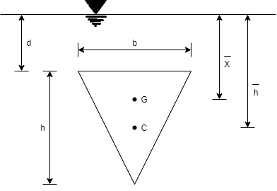
Distance of centroid from free surface

Area of triangle,

Moment of inertia

Centre of pressure


Q.4 A circular plate 2.95 m diameter is immersed in water in such a way that its greatest and least depth below the free surface is 4.1 m and 1.6 m respectively. Determine the total pressure on one face of the plate and position of center of pressure.
Soln.:
Given:
d=2.95 m,
least depth 1.6 m,
Greatest depth 4.1 m
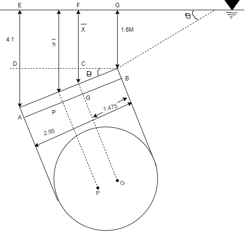
To Find: P and h
Area of plate

Moment of inertia

Distance of c. g. of plate from free surface

1. Total pressure, p

2. Position of center of pressure, h


Q.5 A square plate 6 m x 6 m is placed in a liquid of specific gravity 0.8 at an angle of 30 with free liquid surface. A square hole 1.5 m in size is cut exactly in the center of the plate. Its greatest and the least depths below the free liquid surface are 4 m and 2 m respectively. Determine the total pressure on one face of the plate and position of center of pressure.
Soln.:
Given: S=0.8, 0=30°
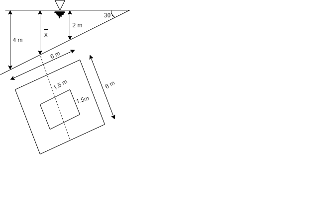
To Find: P and h
Area A=6²-1.5 = 33.75 m²
Position of centroid of lamina from free surface

Moment of inertia,

Total pressure,

Key takeaways:
Centre of Buoyancy
Equilibrium of floating and submerged bodies
Stability of floating Body:
The stability of a floating body is determined from the position of Meta-centre (M).
a). Stable Equilibrium

M is above G ( stable equilibrium ). M is below G ( unstable equilibrium )
Fig no 18 Stability of floating bodies
b. Unstable Equilibrium:
c. Neutral Equilibrium:
Stability of submerged Body:
Stable equilibrium :
When W = FB& point B is above G, the body is said to be in stable equilibrium.
Unstable Equilibrium :
If W = FB , but center of buoyancy B is below the center of gravity G, the body is in unstable equilibrium.
Neutral Equilibrium :
If W = FB & point B & G are at the same point, the body is said to be in neutral equilibrium.
Examples:
Q.1 A solid cube of sides 0.5 m each is made of material of relative density 0.5. Tho cube floats in a liquid of relative density 0.95 with two of its faces horizontal. Examine its stability.
Soln.:
Given:
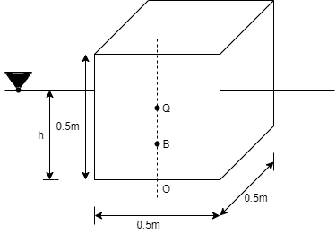
Side a=0.5 m
Relative density 0.5 m
Relative density of cube Sc= 0.5
Relative density of liquid S₁ = 0.95
Weight of cube = Weight of liquid displaced


Depth of immersion (h).

Depth of immersion (h),

Distance of C.G. from O.

Distance of buoyancy from O.

Now, BG= OG-OB=0.25-0.1315 = 0.1185 m

Metacentric height, BM-BG

Negative sign of metacentric height indicates that in unstable equilibrium.
Q.2 A rectangular pontoon is 5 m long, 3 m wide and 1.20 m high. The depth of immersion of the pontoon is 0.80 m in sea water. If the centre of gravity is 0.6 m above the bottom of the pontoon, determine the metacentric height. The density for sea water = 1025 kg/m².
Soln.:
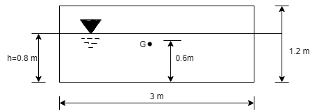
Volume of liquid displaced

Moment of inertia

Metacentric height BM BG=

Key takeaways:
Whenever a body is immersed wholly or partially in a fluid it is subjected to an upward force which tends to lift it up.
The tendency for an immersed body to be lifted up in the fluid due to an upward force opposite to action of gravity is known as buoyancy.
The force tending to lift up the body under such conditions is known as buoyant force or force of buoyancy.
References:
1. Tech max
2. Fluid mechanics and machinery R Berndtsson and P.N. Chadramouli
3. Hydraulic and fluid mechanics, PM Modi and SM Seth
4. Theory and applications of fluid mechanics, K Subramanya, Tata McGraw Hill
5. Fluid mechanics with engineering applications, RL Daughterty, JB Franzini