Unit - 3
Fluid Kinematics
Steady flow – The type of flow in which the fluid characteristics like velocity, pressure, density, etc. at a point do not change with time is called steady flow.
Example: Flow through a prismatic or non-prismatic conduct at a constant flow rate Q m3/s is steady.
Mathematically,  u/
u/  t = 0, w/ t = 0 , p/ t = 0 , rho / t = 0
Unsteady flow: It is that type of flow in which the velocity, pressure or density at a point change w.r.t. time.
E.g.: the flow in a pipe whose value is being opened or closed gradually.
Mathematically,  u/
u/  t not = to 0 , w/ t not = to 0 , p/ t not = to 0 ,
  / t not = to 0
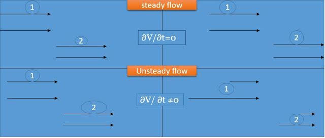
Fig no 1 Steady and unsteady flow
Key takeaways:
The type of flow in which the fluid characteristics like velocity, pressure, density, etc. at a point do not change with time is called steady flow.
It is that type of flow in which the velocity, pressure or density at a point change w.r.t. time.
Uniform flow – The type of flow, in which the velocity at any given time does not change with respect to space is called uniform flow.
E.g.: Flow through a straight prismatic conduit.
Mathematically,  V /
V /  s = 0 when t = constant
Non-uniform flow – It is that type of flow in which the velocity at any given time changes with respect to space.
E.g.: Flow through non-prismatic conduit.
Mathematically,  V/
V/  s not = to 0 when t = constant
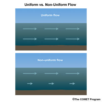
Fig no 2 Uniform and non-uniform flow
Key takeaways:
The type of flow, in which the velocity at any given time does not change with respect to space is called uniform flow.
It is that type of flow in which the velocity at any given time changes with respect to space.
Laminar Flow – A Laminar flow is one in which paths taken by the individual particles do not cross one another and move along well-defined path.
E.g.: Flow of blood in veins and arteries.
Turbulent Flow – A turbulent flow is that flow in which fluid particles move in a zig zag way.
E.g.: High velocity flows in conduit of large size.
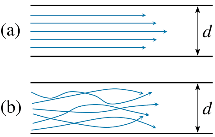
Fig no 3 Laminar and turbulent flow
Key takeaways:
A Laminar flow is one in which paths taken by the individual particles do not cross one another and moves along well-defined path.
A turbulent flow is that flow in which fluid particles move in a zig zag way.
Rotational Flow -A flow said to be rotational if the fluid particles while moving in the direction of flow rotate about their mass centers.
E.g.; Motion of liquid in a rotating tank.
Irrotational flow - A flow said to be rotational if the fluid particles while moving in the direction of flow do not rotate about their mass centers.
E.g.: Flow above a drain hole of a stationary tank or a water basin.
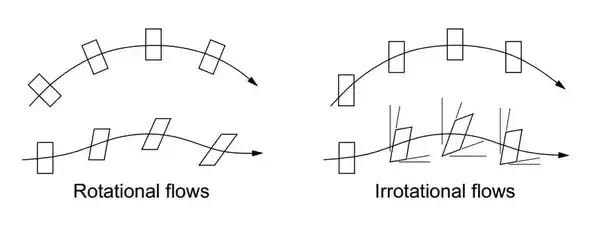
Fig no 4 Rotational and irrotational flow
Key takeaways:
A flow said to be rotational if the fluid particles while moving in the direction of flow rotate about their mass centers.
A flow said to be rotational if the fluid particles while moving in the direction of flow do not rotate about their mass centers.
Compressible Flow – It is that type of Flow in Which the density () of the fluid changes from point to point.
E.g.: Flow of gases through orifices, nozzles, gas turbines, etc.
Mathematically,  not = to constant
Incompressible Flow – It is that type of flow in which density is constant for the fluid flow. Liquids are generally considered flowing incompressible.
E.g.: subsonic aerodynamics.
Mathematically,  = constant
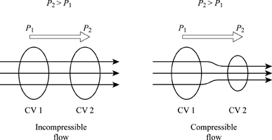
Fig no 5mCompressible and incompressible flow
Key takeaways:
It is that type of Flow in Which the density () of the fluid changes from point to point.
It is that type of flow in which density is constant for the fluid flow. Liquids are generally considered flowing incompressible.
Ideal Fluid
Real liquid
Liquids with viscosity, earth thickness, shear strength, and pressure are called real liquids. All liquids, in fact, are real liquids and provide a certain amount of resistance during liquid movements. The actual liquid is slightly separated as given below.
1. Newtonian fluid
The actual fluid, where the shear pressure is directly proportional to the shear strain level or velocity gradient is known as the Newtonian fluid as shown in Fig. 1.1. Examples of Newtonian liquids are water, air, paraffin, body oils, and glycerine, etc. These liquids follow Newton's law of viscosity.
2. Non-Newtonian fluid
The actual fluid where the shear pressure does not match the degree of shear hardness or velocity gradient is known a s Non-Newtonian fluid. These liquids do not obey Newton's law of viscosity.
3. Ideal plastic or Bingham liquid
Liquids where shear pressure exceeds yield pressure and shear pressure is equal to the level of the shear machine or velocity gradient are more commonly known as the appropriate plastic fluid. Examples of plastic fluids suitable for the suspension of water with clay and fly ash
4. Thixo tropic fluid
These are non-Newtonian liquids with a non-linear relationship between stock pressure and angular fluctuations above a certain yield pressure. Examples of thixo tropic liquids with crude oil, Benton tic liquid drilling fluid and printer ink, etc.
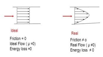
Fig no 6 Ideal and real fluid flow
Key takeaways:
Ideal fluid is a fluid that is unmistakable and has no internal resistance to flow (zero viscosity).
Liquids with viscosity, earth thickness, shear strength, and pressure are called real liquids.
One dimensional flow – it is that type of flow in which the flow parameter such as velocity is a function of time and one space coordinate.
E.g.: Flow in a pipe where average flow parameters are considered for analysis.
Mathematically, u = f(x), v = 0 & w =
Two-dimensional Flow – The flow in which the velocity is a function of time and two rectangular space coordinates is called two-dimensional flow.
E.g.: Flow between parallel plates of infinite extent.
Mathematically, u = f1(x,y) v = f2(x,y) & w = 0
Three-dimensional flow – It is that type of flow in which the velocity is a function of time and three mutually perpendicular directions.
E.g.: Flow in a converging or diverging pipe or channel.
Mathematically, u = f1(x,y,z) v = f2(x,y,z) & w = f3(x,y,z)
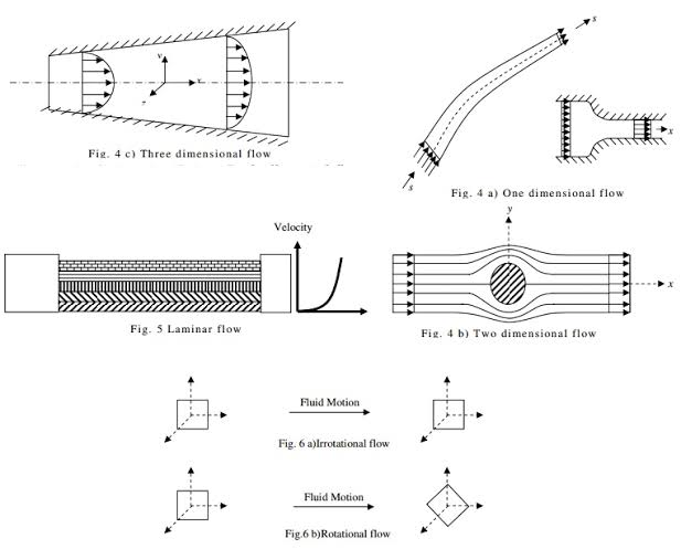
Fig no 7 One two- and three-dimensional flow
Key takeaways:
It is that type of flow in which the flow parameter such as velocity is a function of time and one space coordinate.
It is that type of flow in which the velocity is a function of time and three mutually perpendicular directions.
It is that type of flow in which the velocity is a function of time and three mutually perpendicular directions.
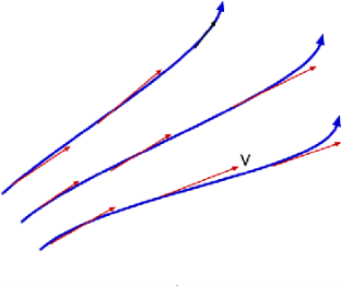
Fig no 8 Stream line
Examples:
Q.1 The velocity of a flow is given by v = -x i + 2y j + (5 - 2) k. Derive the equation of streamline passing through a point (2, 1, 1).
Soln.:
u = -x, v = 2y and w = 5-z
The streamline, put the value of u, v and w

Consider,


 Stream line passing through x=2, y=1, z= 1


Now consider,


Stream line passing through x=2, z=1


Q.2 For the three-dimensional flow, the velocity distribution is given by u-x, v-4-2y, w z-2. What is the stream line equation passing through (1.-2, 3).
Soln.:
The streamline,

Put the value of u, v and w

Consider 
By integrating


Stream line passing through x=1 y= =-2


Now considering


From equation

Q.3 The velocity component in a steady flow are u=2kx, v= 2ky, w = - 4kz. What is the through the point (1, 0, 1).
Soln.:
The streamline,

Put the value of u, v and w

Now considering


Stream line passing through x = 1, z=3,


This is the equation of streamline passing through the point (1,0,1)
Q. 4 The velocity field for a two-dimensional flow is given by V= 4x³i-12x²yj. What is the equation of streamlines?
Soln.:
Velocity vector v = 4x'i-12x²yj
Velocity component u = 4x², v = -12x²y
Stream line


By integrating,
3 log x = -log y + log C


The curve defined by x³y = C₁, C₂, C, ...etc.
Key takeaways:
A streamline may be defined on as an imaginary line within the flow so that the tangent at any point on it indicates the velocity at that point.
An important concept in aerodynamics research touches on the concept of simple methods. The arrangement is the process followed by the weightless particles as they flow and flow.
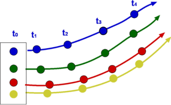
Fig no 9 Path lines
Key takeaways:
Path lines are the trajectories that are followed by the particles of each body. This can be thought of as "recording" the method of a liquid object in a certain flow of time. The direction of the path to be determined will be determined by the fluid flow of the liquid at each time point.
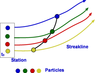
Fig no 10 Streak line
Redirect is a line that positively connects velocity vectors over a period of time. In other words, the flow diagram presented in simple lines is similar to the abstract flow at the same time.
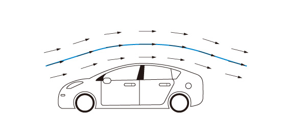
Fig no 11 Stream line example
A streak line is a curved line formed by a string of liquid particles that pass through a certain area. An example of a streak line is the smoke path from the chimney.
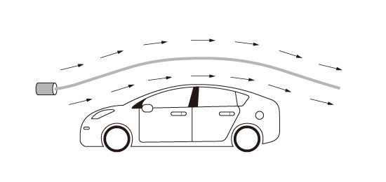
Fig no 12 Streak line example
Path line is the process followed by liquid particles. One example of a path line is a method described as a balloon floating in the air.
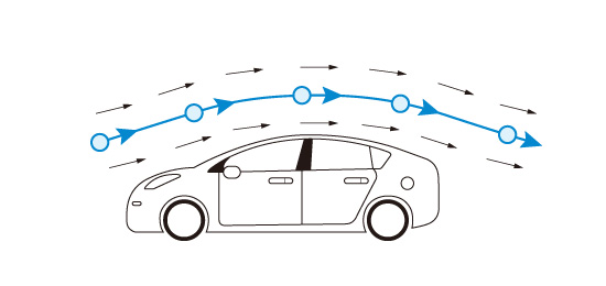
Fig no 13 Path line example
With constant flow, streamline, streak line, and path line are the same line. The constant flow of time is called the steady flow. On the other hand, the flow that varies with time is called transient flow. In the short-term flow, streamline, streak line, and path line are all different lines.
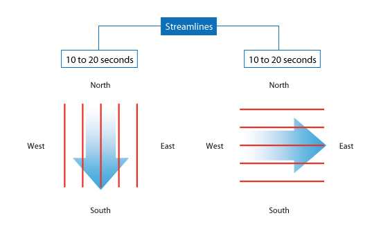
Fig no 14 Stream line direction
The streak line represents all the points that have passed in one place. In this case, where the streak line can be compared to represent the chimney from the chimney, the streak line goes south within the first ten seconds because all the smoke goes south. Then, when the wind blows eastward, all the smoke particles that start to move south (released by Time <10 seconds) begin to be placed eastward. New smoke particles (released Time> 10 seconds) are oriented eastward. After 20 seconds the streak line is in the right corner as shown on the right
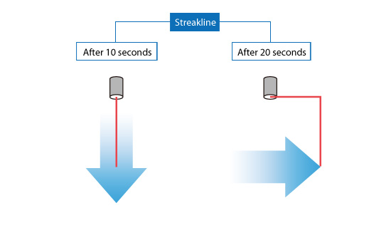
Fig no 15 Streak line direction
The pathline goes south within the first 10 seconds as a streakline. The pathline can be thought of as a process followed by a balloon floating in the air. When the wind shifts eastward, the balloon begins to move eastward. The pathline goes east from where the direction of the wind is changed. As a result, after 20 seconds the pathline bends at the right angle as shown on the right
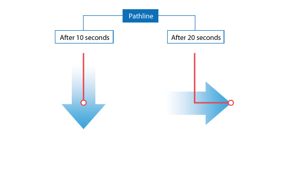
Fig no 16 Path line direction
As can be seen in this chapter, the results of the temporal flow analysis will vary depending on the method used to detect the flow. Understanding these differences is important when looking at analysis and test results.
Key takeaways:
A streak line is a curved line formed by a string of liquid particles that pass through a certain area. An example of a streak line is the smoke path from the chimney.
Path line is the process followed by liquid particles. One example of a path line is a method described as a balloon floating in the air.
It is defined as the scalar function of space and time such that its partial derivative with respect to any direction gives the velocity component at right angles to that direction.
It is denoted by Ψ (psi) and defined only for two-dimensional flow.
Mathematically, for ready flow it is defined as Ψ = f(x, y) such that
 Ψ /
Ψ /  x= v
x= v
And  Ψ /
Ψ /  y = -u
Examples:
Q.1 A stream function is given by  check if the flow is rotational and satisfies continuity equation
Soln.:

By definition


Velocity


1) Irritational flow

2) Continuity equation


The flow is not continuous
Q.2 Determine whether the following specified flows are rotational or otherwise. Determine the expression for the velocity potential in case of irrotational flow

Soln.:
For rotational flow


Flow is rotational.
Key takeaways:
It is defined as the scalar function of space and time such that its partial derivative with respect to any direction gives the velocity component at right angles to that direction.
The velocity potential is defined as scaler function of space and time such that its negative derivative with respect to any directions gives the fluid velocity in that direction.
It is denoted by Ø (phi)
Thus, mathematically the velocity potential is defined as
Ø = f(x, y,z,t)
And Ø = f(x, y, z)
u = -  Ø /
Ø /  x
x
v = -  Ø /
Ø /  y
y
w = -  Ø /
Ø /  z
z
Where u, v and w are the components of velocity in the x, y and z directions respectively.
The negative sign signifies that Ø decreases with an increase in the values of x, y and z. in other words, it indicates that the flow is always in the direction of decreasing Ø.
Examples
Q.1 the velocity potential function is given by an expression 
1) Find the velocity components in x and y direction
2) Show that  represents a possible case of flow
Soln.:

Case I) the partial derivation of  w.r.t x and y are


The velocity components u and v


Case II) The value of  represents a possible case of flow if it satisfy the laplace equation


 Represents possible case of flow
Q.2 the velocity potential function for a two dimensional flow is  at a point P (4, 5) determine
1) The velocity and
Soln.:
Velocity potential

Differential w.r.t x
Hence

By definition of 


Velocity at P (4, 5)


Flow is continuous
Key takeaways:
The velocity potential is defined as scalar function of space and time such that its negative derivative with respect to any directions gives the fluid velocity in that direction.
One dimensional
The continuity equation is based on the principle of conservation of mass. It states as follows
If no fluid is added or removed from the pipe in any length then the mass passing across different sections shall be same.
Consider two cross-sections of a pipe as shown in fig.
Let, A1&A2 = Areas of the pipe at section 1-1 & section 2-2 respectively.
V1 & V2 = Velocities of the fluid at section 1-1 & section 2-2 respectively.
1 &2 = Densities of the fluid at section 1-1 & section 2-2 respectively.
Total quantity of fluid passing through the section 1-1 = 1A1V1
Total quantity of fluid passing through the section 2-2 = 2A2V2
From the law of conservation of matter
1 A1 V1 = 2 A2 V2
In case of incompressible fluids 1 =2
A1 V1 = A2 V2
Three dimensional
Considers a fluid element (control volume)- parallelepiped with sides dx, dy and dz as shown in fig.
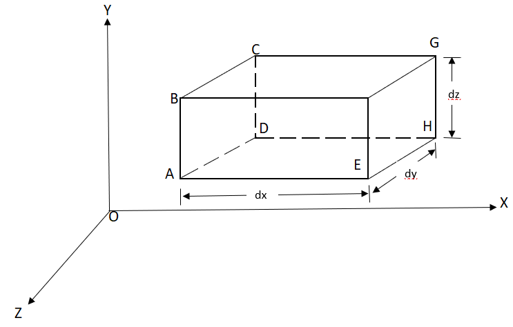
Fig no 17 3d continuity equation
Let,  = Mass density of the fluid at a particular instant
u, v, w= components of velocity of flow entering the three faces of the parallelepiped.
Rate of Mass of fluid entering the face ABCD
=  X velocity in x-direction X area of ABCD
= u dy dz
Rate of Mass of fluid leaving the lace FEGH
=  u dy dz +
:. Mass accelerated per unit time, due to flow in x-direction
=  u dy dz –[
 u+
u+ dx]dydz
= - - (
( u) dx dy dz
Similarly, the gain in fluid mass per unit time in the parallelepiped due to flow in Y and Z- direction.
=  (
( v) d x d y d z ……… (in Y- direction)
=  (
( w) d x d y d z ……… (in Z- direction)
The, total gain in fluid mass per unit for fluid along three co-ordinate axes
= -[ (
( u) +
u) + (
( v) +
v) +  (
( w)] dx dy dz …………1
Rate of change of mass of the parallelepiped (control volume)
=  (
( d x, d y d z) ………………….. 2
From Equation 1& 2
-[ (
( u) +
u) + (
( v) +
v) + (
( w)] dx dy dz =
  (
( dx dy dz)
Simplification and rearrangement of teams would reduce the above expression to
 (
( u) +
u) +  (
( v) +
v) +  (
( w) +
w) +  =0
=0
This eq. is the general equation of continuity in three dimension and is applicable to any type of flow and for any fluid whether compressible as incompressible
For steady flow ( =0) incompressible fluids (
 = constant) the equation reduces to
 +
+ +
+ =0
=0
For two dimensional flow eq. reduce to
Examples:
Q.1 The velocity components for a two-dimensional incompressible flow is given by
1) u = 4 xy + y². v = 6 xy + 3x
2) 
Check whether the flow satisfies continuity?
Soln.:
(i) u = 4 xy + y², v = 6 xy + 3x
Differentiating


For two dimensional flow continuous equation is


Velocity components does not satisfy the continuity equation
ii) 
Differentiating
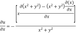


For two dimensional flow continuous equation is


Satisfy the continuous equation.
Q.2 The velocity components for a three dimensional incompressible flow is given by: 
Check whether the flow satisfies continuity?
Soln.:


Foe three dimensional equation continuous equation is


The flow is satisfy
Q.3 The velocity field is given by  check whether the flow satisfies continuity?
Soln.:
Velocity field

Velocity component

For three dimensional flow


Steady incompressible fluid flow is possible.
Key takeaways
If no fluid is added or removed from the pipe in any length then the mass passing across different sections shall be same.
One dimensional
Two dimensional
Three dimensional
References:
1. Fluid mechanics and machinery R Berndtsson and P.N. Chadramouli
2. Hydraulic and fluid mechanics, PM Modi and SM Seth
3. Theory and applications of fluid mechanics, K Subramanya, Tata McGraw Hill
4. Fluid mechanics with engineering applications, RL Daughterty, JB Franzini