Unit - 4
Fluid Dynamics
The motion of the fluid element is influenced by the following forces

Fig no 1 Surface and body forces
1. Normal pressure force
The net pressure force in X direction = p dydz – ( p +  p/
p/  X dx) dy dz
= -  p/
p/  X dx dy dz
2. Gravity or body force
Let B be the body force per unit mass of fluid having components Bx, By&Bz
In x, y & z directions respectively.
Then, body force acting on the parallelepiped in the direction of X coordinate is = Bxdx dydz
3. Inertia force
The inertia force acting on the fluid mass, along the X coordinates is given by,
Mass x acceleration =  dx dydz du/ dy
Key takeaways
Normal pressure force
Gravity force
Inverted force
Consider steady flow of an ideal fluid along the shown tube.
Separate out a small element of fluid of cross- sectional area dA and length ds from stream tube as a free body from the during fluid.
Fig. shows such a small elements LM of fluid of cross Section area dA and length ds.
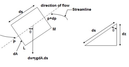
Fig no 2 Equation of motion Diagram
Let, p= Pressure of an the elements at L
p + dp = Pressure on the element at M,and
V=Velocity of the fluid element.
The external forces tending to accelerate the fluid elements in the direction of streamline are as follows:
Net pressure force in the direction of flows is, p.dA – (p+dp)dA = -dp. dA
Component of the weight of the fluid elements in the direction of flows is
= - rho.g.dA.ds.cos
=- rho.g.dA.ds (dz/ds) (:. Cos = dz/ds)
= - rho .g.dA.dz
Mass flow of the fluid element =  .dA.ds
The Acceleration of the fluid element
a = dv/dt = dv/ds * ds/dt = v. dv/ds
Now , according to Newton’s second law of motion, force= mass x acceleration.
:. – dp. dA.-  .g.dA.dz=
 .dA.ds x v.dv/ds
Dividing both sides by rho .dA, we get
-dp/- . g.dz= v.dv
Or dp/ + v.dv + g.dz=0
This is the required Euler’s equation for motion.
Integrating the Euler’s equation of motion we get
1/ ∫ d p +∫v. d v+ ∫g.dz=constant
p/ ρ + v2 /2 + g z = constant
Dividing by g, we get
p/  g + v 2/2g + z = constant
p /w + v 2/2g + z = constant
Or in other words, P1/ W+V1 2 / 2 g +Z1=P2/ W+V22 / 2g+Z2
Which proves Bernoulli’s equation
Key takeaways
Euler equation is given as
P1/ W+V1 2 / 2 g +Z1=P2/ W+V22 / 2g+Z2
Assumptions made in Bernoulli’s equation.
Bernoulli equation
Where h L= Loss of energy between section 1 & 2.
Applications of Bernoulli’s equation
Bernoulli’s equation is applied is all problems of incompressible fluid flow where energy considerations are involved, But we shall consider its applications to the following measuring devices:
Limitation of Bernoulli’s equation
Key takeaways
Bernoulli’s equation is derived based on the assumption that fluid is non viscous & therefore frictionless.
These losses have, therefore, to be taken into account in the application of Bernoulli’s equation which gets modified as follows
P1/ W+V1 2 / 2 g +Z1=P2/ W+V22 / 2g+Z2 + h L
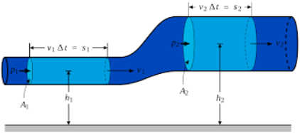
Fig no 3 Energy principal determination apparatus
Key takeaways
The principle applies only to isentropic flow: where the effects of irreversible processes (such as disorder) and non-adiabatic processes (e.g. heat radiation) are small and ignored.
Bernoulli's system can be applied to a variety of fluid flows, leading to a variety of Bernoulli's calculations; there are different types of Bernoulli's figure for different types of flow.
The simplest form of Bernoulli's equation is valid for unmistakable flow (e.g. high flow of air and gases running through a low March number). Advanced forms can be used for pressurized flow in high March numbers (see Bernoulli statistical availability).
A venturi meter is a device used for measuring the rate of a flow of a fluid flowing through a pipe it consists of three parts:
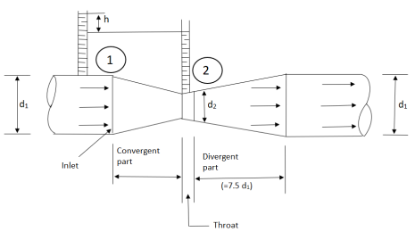
Fig no 4 Venturimeter
It is based on the principle of Bernoulli’s equation.
Expression for Rate of flow through venturimeter
Consider a venturimeter fitted in a horizontal pipe through which a fluid is following as shown in fig.
Let d 1 = diameter at inlet or at section (1)
P 1= pressure at section (1)
V 1= velocity of fluid at section (1)
A 1= area of section (1) =π/4. D2
And d 2, P 2, V 2, a 2 are corresponding values at section (2)
Applying Bernoulli’s equation at section (1) and (2) we get
P1/  g+V12 /2g+Z1=P2 /
  g+V22 /2g+Z2
As pipe is horizontal hence z 1 = z2
P1/  g+V12 /2g =P2 /
  g+V22 /2g
(P1 – p 2 )/  g = V22 /2g - V12 /2g
But (P1 – p 2 )/  g is the difference of pressure heads at section land 2 and it is equal to h
∴(P1 – p 2 )/  g =h
g =h
Substituting this value of (P1 – p 2 )/  g in the above eqn we get.
∴ h = V22 /2g - V12 /2g………….. (1)
Now applying continuity equation at section 1 and
a 1 v 1 = a 2 v 2
∴ v 1 = a 2 v 2 / a 1
Substituting this value of v 1 in equation 1
h= V22 /2g – (a 2 v 2 / a 1) 2 / 2 g
h= V22 /2g [ (a 12 –a 22 )/ a 12 ]
V22 = (2 g h a 12 )/ (a 12 –a 22)
Q = a2 v 2
= [a 1 a 2 /  ( a 12 –a 22 ) ] *
  ( 2 g h ) ]
Above equation gives the discharge under ideal conditions and is called, Theoretical discharge Actual discharge will be less than theoretical discharge.
Q act = C d * [a 1 a 2 /  ( a 12 –a 22 )] *
  ( 2 g h ) ]
Where C d = co-efficient of venturimeter and its value is less than 1.
Key takeaways
A venturimeter is a device used for measuring the rate of a flow of a fluid flowing through a pipe
Q act = C d * [a 1 a 2 /  ( a 12 –a 22 ) ] *
  ( 2 g h ) ]
ORIFICE METER
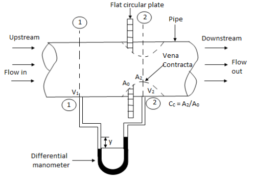
Fig no 5 Orifice meter
(1) Which is at a distance of about 1.5 to 2.0 times the pipe diameters upstream from the orifice plate, and at section
(2) Which is at a distance of about half the diameters of the orifice on the downstream side from the orifice plate.
PITOT TUBES
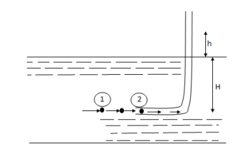
Fig no 6 Pitot tubes
P1= intensity of pressure at point (1)
V1 = velocity of flow at (1)
P2 = pressure at point (2)
V2 = velocity at point (2), which is zero
H = depth of tube in the liquid.
h = rise of liquid in the tube above the fire Surface
Applying Bernoulli’s equation at points (1) and (2)
We get
P1/ W+V1 2 / 2 g +Z1=P2/ W+V22 / 2g+Z2
But Z 1 = Z2as points (1) and (2) are the same line and V2 =0
P1 /g= pressure Lead at (1) = H
P2 /g = pressure head at (2) = (h +H)
Substituting these values, we get
H+ V1 2 / 2 g = (h+H)
:. h= V1 2 / 2 g or v 1 =  (2 g h )
This is theoretical velocity.
Actual velocity is gives by (V 1) = Cv (2 g h)
Where C v= Co-efficient of pitot-tube
:. Velocity at any point V= Cv (2 g h)
Key takeaways
Orifice meter
It is a device used for measuring the rate of flow of a fluid through a pipe.
It is a cheaper device compared to venturimeter
It also works on the same principle as that of venturimeters.
It consists of a flat circle plate which has a circular shapes edged holed called orifice, which is concentric with the pipe.
Pitot tubes
It is a device used for measuring the velocity of flow at any point in a pipe or a channel.
It is based on the principle, that if the velocity of flow at a point becomes zero, the pressure there is increased due to the conservation of the kinetic energy into pressure energy.
F = m x a
Where a is the acceleration acting in the same direction as force F
But a = d v /d t
F = m x d v /d t
= d (m v) /d t, m is constant can be taken inside the differential
Above equation is known as the momentum principle.
It can be written as F d t = d (m v)
Which is known as the momentum equation & states that the impulse of force F acting on a fluid of mass m in a short interval of time dt is equal to the change of momentum d(m v) in the direction of force.
Momentum Correction Factor( )
)
Momentum correction factor is defined as the ratio of momentum of the flow per second based on actual velocity to the momentum of the flow per second based on average velocity across a section. It is denoted by.
 = Momentum per second based on actual velocity/ Momentum per second based on average velocity
 = 1 for uniform flow
 = 1.01 to 1.07 for turbulent flow in pipes
 = 4/3 = 1.33 for laminar flow in pipes.
Key takeaways
It is based on law of conservation of momentum or on the momentum principle, which states that the net force acting on a fluid mass is equal to the change in momentum of flow per unit time in that direction.
F = m x d v /d t
The energy produced by the liquid flowing in the pipe - bending
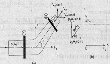
Fig no 7 The energy produced by liquid flowing in bending pipe
V1 = Speed of liquid flowing in phase 1
P1 = Pressure fluid pressure in phase 1
A1 = Section 1 location
V2 = Speed of liquid flowing in phase 2
P2 = Pressure fluid pressure in phase 2
A2 = Section 2 location
FX = The energy released by the liquid flowing in the rotation of the pipe in the X-direction.
FY = A police force that causes fluid to flow in a pipe turn in a Y-direction.
Net power applied to the liquid in the X-direction = Level of pressure change in the X-direction
P1A1 - P2A2 Cos θ - FX = Mass at each unit time x velocity change
P1A1 - P2A2 Cos θ - FX = ρ Q (Final speed in X direction - First velocity in X-direction)
P1A1 - P2A2 Cos θ - FX = ρ Q (V2 Cos θ - V1)
FX = ρ Q (V1 - V2 Cos +) + P1A1 - P2A2 Cos θ
Net power applies to liquids in Y-direction = Level of pressure change in Y-direction
- P2A2 θ sin - FY = Mass for each unit time x speed change
- P2A2 Sin θ - FY = ρ Q (Final velocity in Y direction - First velocity in Y direction)
- P2A2 θ sin - FY = ρ Q (V2 Sin θ - 0)
- P2A2 θ sin - FY = ρ Q (V2 Sin θ - 0)
FY = ρ Q (-V2 Sin θ) - P2A2 Sin θ
Let us determine the following (FR) forces acting on the bending of the pipe and the bending of the angle with the resulting force (FR) with the horizontal direction.
F = √ ( Fx2 + Fy2 )
Tan θ = Fy/ Fx
Key takeaways
In order to prevent the reflection of the resulting force applied by the liquid flowing into the bend pipe, we will use the basic concept of impulse pressure equation. Before proceeding, it is very important to find and learn the concept of equation intensity.
F = √ ( Fx2 + Fy2 )
Tan θ = Fy/ Fx
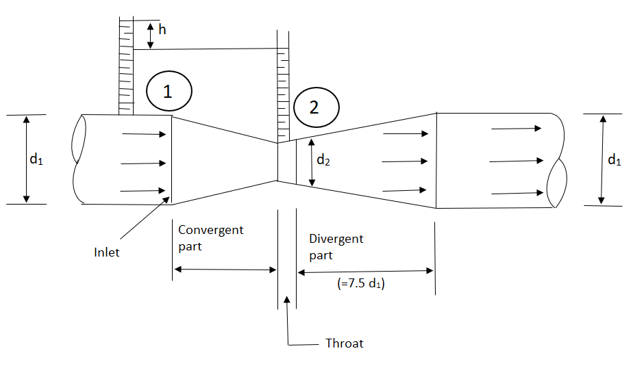
Fig no 8 Vortex flow
Vortex flow: the circulating weight of a liquid or a liquid flow in a curved path.
Free vortex flow
For a Free vortex flow
v r = constant or v = c/ r
Free vortex flow - Velocity equation
At the center (r = 0) of the velocity rotation approaches infinitely, that point is called a single point.
Examples include a whirlpool in a river, water flowing from a bathtub or sink, flowing into the space of a centrifugal pump and flowing around a circular bend of a pipe.
Forced vortex flow
v = r ω
ω = Angular speed.
r = Radius of particle fluid from the axis of rotation.
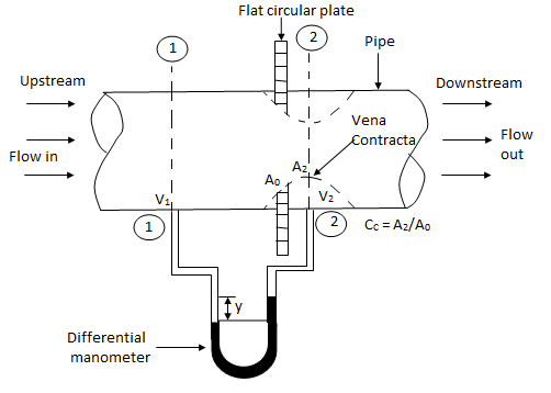
Fig no 9 Forced vortex Verified vortex - Height rate
Examples of forced vortex flow rotate a vessel containing a liquid with constant angular velocity, flowing within a centrifugal pump.
Key takeaways
There are two types of vertex
Reynolds number
With respect to laminar and turbulent flow regimes:
Reynolds' number is described as
Re = u L / 
Where:
 is the humidity (SI units: kg / m3)
u is flow speed (m / s)
L different line size (m) (see paragraphs below this article for examples)
μ is the strong viscosity of the fluid (Pa · s or N · s / m2 or kg / (m · s))
 is the kinematic viscosity of fluid (m2 / s).
Froude number
Froude’s number, Fr, is an infinite number that describes the various states of open channel flow. Froude's number is a measure of gravity and gravity.
Gravity (number) - moves water down
Inertia (denominator) - shows its willingness to do so.
Fr = v / √ (g D)
Where:
V = Water speed
D = Hydraulic depth (flow area / over width)
g = Gravity
When:
Fr = 1, critical flow
Fr> 1, basic flow (fast flow)
Fr <1, poor flow (slow / silent)
Mach number
Mach (M or Ma) number is an infinite magnitude in the force of a liquid that represents the rate of flow rate beyond the local speed limit.
M = u / c
Where: M local Mack number,
u is the local velocity flow in relation to boundaries (either internal, such as something flow-focused, or external, as a channel), and
c is the speed of the sound in the middle, in the air which varies with the square root of the thermodynamic temperature.
Weber number
Weber (We) is a flawless number for liquid technologies that are often useful in analyzing fluid flow where there is a connection between two different liquids, especially multiphase flow with tightly curved surfaces. Named by Moritz Weber (1871–1951).
It can be considered as a measure of the relative importance of fluid inertia compared to groundwater. The quantity helps to test the small flow of the film and the formation of droplets and bubbles.
Euler number
In the statistics, the Euler numbers sequence En numbers (A122045 sequence in OEIS) described the extension of the Taylor series
1/ cosh t = 2 / et + e-t
Where cosh t is hyperbolic cosine .Euler numbers are associated with a specific number of Euler polynomials, namely:
E n = 2 n E n (1/ 2)
Euler's numbers come from the growing series of Taylor's secretive and hyperbolic secant activities. The latter is a function in the definition. They also appear in combinations, especially when calculating the number of exchange permissions for a set with a number of items.
Key takeaways
Reynolds (Re) number helps to predict flow patterns in various fluid flow conditions. In low Reynolds numbers, the flow is usually dominated by laminar (sheet-like) flow, while at high Reynolds numbers the flow is often chaotic.
Froude’s number, Fr, is an infinite number that describes the various states of open channel flow. Froude's number is a measure of gravity and gravity.
By definition, in March 1, the local flow speed is equal to the speed of the sound. In March 0.65, 65% is subsonic speed, and, on March 1.35, 35% is faster than supersonic speed.
Weber (We) is a flawless number for liquid technologies that are often useful in analyzing fluid flow where there is a connection between two different liquids, especially multiphase flow with tightly curved surfaces. Named by Moritz Weber
Euler's numbers come from the growing series of Taylor's secretive and hyperbolic secant activities. The latter is a function in the definition
“If there are n variables in a dimensionally homogeneous equation and if these variables contain fundamental dimensions (such as M, L, T, etc.) then the variables are arranged into (n-m) dimensionless terms.
Mathematically, if any variable X1, depends on independent variables, X2, X3, X4,…… Xn; the functional equation may be written as
 -------- 1
Equation 1 can also be written as
 -------- 2
It is dimensionally homogeneous equation and contains n variables.
If there are m fundamental dimensions, then according to Buckingham’s Π – theorem, it can be written in terms of number of Π – terms in which number of Π terms is equal to (n-m).
Hence equation 2 becomes as
 --------3
Each dimensionless  – term is formed by combining m variables out of the total n variables with one of the remaining (n-m) variable.
These m variables which appear repeated in each of  – terms are consequently called repeating variables and are chosen from among the variables such that they together involve all the fundamental dimensions and they themselves do not form a dimensionless parameter.
Let in the above case X2, X3 and X4 are the repeating variables if the fundamental dimensions m(M, L, T) = 3, then each term is written as:


.
.
.
 -------- 4
Where a1, b1, c1, a2, b2, c2 etc. are the constants, which are determined by considering dimensional homogeneity. These values are substituted in equation 4 and values of  are obtained. These values of Π’s are substituted in equation 3.
The final general equation for the phenomenon may then be obtained by expressing anyone of the Π – terms as a function of the other as:


Key takeaways:
The final general equation for the phenomenon may then be obtained by expressing anyone of the Π – terms as a function of the other as:


Examples:
Q.1 Water is flowing through a tapered pipe having diameters 300 mm and 150 mm at section 1 and 2 respectively. The discharge through the pipe is 40 litre/sec. Section 1 is 10 m above datum and section 2 is 6 m above datum. Find the intensity of pressure at section 2 if that at section 1 is
Soln.:
Given
Q = 40 litre/sec=0.04 m²/sec
Z₁ = 10m
Z₂ =6m
d₁ =300mm=0.3 m
d2 = 150 mm-0.15m
P1 = 400 kN/m²
To find: P:
Area


By continuity equation,


By Bernoulli's equation


The intensity of pressure of section 2 is 436.84 kN/m²
Q.2 A pipe has a length of 200 m with a slope of 1 in 100. The diameter of pipes changes from 1.0 m at higher end to 0.5 m at lower end. Find the pressure at the lower end if the discharge flowing through pipe is 5.00 m/min and pressure at higher end is 45 kN/m².
Soln.:
Given:
L = 200 m,
P₁ =45 kN/m²
Slope = 1 in 100. z₁ = 0,
d₂ -0.5 m
Q = 5 m/min =5/60 = 0.0833 m/sec
To find: P₂
Slope of pipe is 1 in 100


(Since it is below z₁
i.e., datum, it is considered negative) = -2m
By continuity equation


By Bernoulli's equation


Multiplying by 9.81

Q.3 In a vertical pipe conveying oil of specific gravity 0.8, two pressure gauges has been installed at A and B, where diameters are 16 cm and 8 cm respectively. A is 2 m above B. The pressure gauge readings have shown that pressure at B is greater than at A by 0.981 N/cm². Neglecting all losses calculate flow rate,
Soln.:
Given:
Specific gravity S=0.8
Diameter at A, dA = 16 cm = 0.16 m
Diameter at B, dB = 8 cm=0.08 m ZA = 2 m, ZB=0
PB=PA+0/981 N/cm^2

Pressure difference PB-PA= 9.81KN/m^2
Area


By continuity equation,


By Bernoulli's equation


Discharge

Q.4 The top and bottom diameters of a 2m long vertical tapering pipe are 100 mm and 50 mm respectively. Water flows down the pipe at 30 liters por second. Find the pressure difference between the two ends of the pipe.
Soln.:
Given:
Q = 30 Lps = 0.03 m³/sec,
d1 = 0.05 m. d₂ = 0.1 m, z₁ = 0, z₂ = 2 m
Area


By continuity equation,


By Bernoulli's equation


:. The pressure difference between two ends of pipe is 10.415x 10³ Pa
Q.5 Obtain an expression for pressure drop from inlet to throat in a horizontally mounted venturimeter in terms of rate of volume flow (0) and inlet diameter (D) for inlet throat diameter ratio is equal to 2.
Soln.:
d1= Inlet diameter = D
Inlet diameter /Throat diameter= 2
d2 = Throat diameter = D/2
By continuity equation


By Bernoulli's equation


Q.6 A venturimeter has an area ratio 9.1, the large diameter being 30 cm. During the flow, the recorded pressure head in the large section is 7.75 m and that at the throat is 5.5 m. Find the discharge through the meter if C,0.98.
Soln.:
Given:


Discharge of inlet
d1 = 0.3 m
pressure at inlet 
Pressure head at throat 
Coefficient of discharge Cd, = 0.98
Area


Pressure head

Discharge


Q. 7 A venturimeter is to be fitted to a pipe of area 0.01787 m² A maximum discharge of 5 m/min under a pressure of 4.5 m flows through the pipe. Find the diameter at the throat for no negative pressure at the throat.
Soln.:
Given:
a1 = 0.01767 m². Q = 5 m²/min=0.08333 m/sec
Pressure head = 4.5 m
To find: Diameter of throat i.e. d
Considering the venturimeter to be horizontal
Applying Bernoulli’s equation at section (1) and (2)


But Z1=Z2
And as there is no negative pressure at throat considering


Discharge Q

(Assuming C=0.98)


Q.8 A venturimeter is fitted to 25 cm diameter pipe. A discharge 10 m³/s flowing through venturimeter, develops a venturi head of 3.5 m of water. Find the minimum diameter of throat so that there is no negative head developed.
Soln.:
Given:
D = 25 cm = 0.25 m, Q = 10 m³/s,
To find:
d for no negative head developed.
a₁ = area of inlet = 

Cd=1


Squaring both side


Q. 9 A jet of water 50 mm diameter is discharging under a constant head of 70 metres. Find the force exerted by the jet on a fixed plate. Take coefficient velocity as 0.9.
Soln.:
Given:
d = 50 mm = 0.05 m; H = 70 m
and Cd= 0.9
We known that cross-section area of the jet,

Velocity of the jet,


Force exerted by the jet on the fixed plate,

Q.10 A horizontal jet of water is issuing under an effective head of 25 m calculate the diameter of the jet if the force exerted by the jet on a vertical plate is 2.22 KN. Take Cv =1
Soln.:
Given:
H=25 m; F= 2.22 kN and Cv=1
Let d = Diameter of the jet in meters
We know that cross-section area of the jet,

Velocity of the jet,


Force exerted by the jet on the fixed plate,


Q.11 A jet of water of 100 mm diameter, moving with a velocity of 20 m/s striker a stationary plate Find the force on the plate in the direction of the jet, when
(a) The plate is normal to the jet, and
(b) The angle between the jet and plate is 45°.
Soln.:
Given:
d = 100 mm= 0.1 ni; V=20 m/s and 8 = 45°.
(a) Force on the plate when it is normal to the jet
We known that cross-section area of the jet,

and force on the plate when it is normal to the jet,


(b) Force on the plate when the angle between the jet and plate is 45%
We also known that force on the plate when the angel between the jet the and plate is 45°,
F =  av² = 1x sin²45
= 3.142 sin² 45° = 3.142 x (0.707)² = 1.57 kN
Q.12 A submarine is cruising at a depth of 20 m in ocean water (density 1020 kg/m). If the forward speed of the submarine is 10 m/s, what readings would be given by pitot and static pressure probes? Assume static probe is located to register free stream static pressure.
Soln.:
Given:
Speed V = 10 m/s

:. Velocity of submarine


Dynamic pressure

At 20 m depth, static pressure

Pitot Probe pressure = Static pressure + Dynamic pressure
= 200.124 +51
= 251.124 kPa
Q.13 A pitot tube records of 7.85 kN/m² as the stagnation pressure when it is head at the centre of pipe of 250 mm diameter conveying water. The static pressure in the pipe is 40 mm of mercury (gauge-vacuum). Calculate the discharge through the pipe assuming that the mean velocity of flow is 0.8 times the maximum velocity. Take C, = 0.98.
Soln.:
Given:
Stagnation pressure p₁= 7.85 kN/m²
Pressure at center of pipe = 40 mm of mercury
P2 = -0.04×13.6 x 9.81-5.336 kN/m
Mean velocity = 0.8 x maximum velocity
Pressure head

Maximum velocity

Mean velocity (V)=0.8 x Maximum velocity = 0.8 x 5.033=4.0264 m/sec
Discharge Q

Discharge through the pipe 197.65 Lps.
Q.13 A pitot static tube is used to measure velocity of an aeroplane. U-tube differential manometer gives deflection of 100 mm of water. If specific weight of air is 12 N/m and coefficient of pitot tube is 0.98. Determine speed of aeroplane. Neglect compressibility effects.
Soln.:
Given:
C = 0.98. Ya = 12 N/m².
x = 100 mm of water = 0.1m
To find: Speed of aero plane V = ?
Specific gravity of air

Specific gravity of water
Sw = 1

Speed of aircraft

The speed of aeroplane is 39.28 m/s.
Q. 14 An Orifice of diameter 12 cm is inserted in a pipe of 24 cm diameter. The end pressure gauge fitted upstream and 2 downstream of the orifice metre gives readings 29.43 N/cm and 14.72 N/cm respectively. Co-efficient of discharge of orifice metre is given by 0.6. Find the discharge of water through pipe.
Soln.:
Given:
d= 24 cm = 0.24 m, p, 29.43 N/cm² = 294.3 kN/m² 4-12 cm-0.12 m. p₂= 14.72 N/cm² Cv= 0.6
Area A₁


Pressure difference

Discharge, Q


The discharge through the pipe is 120 Lps.
References: