Unit - 2
Compound Stresses and Strains
1. Two Dimensional System:
A two-dimensional Cartesian coordinate system is shaped by two jointly perpendicular axes. The axes intersect on the factor O, that's referred to as the origin. The x-coordinate of the factor is referred to as the abscissa of the factor, and the y-coordinate is referred to as its ordinate
2. Member subjected to normal stresses in two mutually perpendicular direction accompanied by a simple shear stress:
Consider a rectangular element ABCD of uniform cross-sectional area and unit thickness as shown in fig.
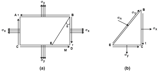
Fig:1
It is subjected to two normal stresses  and
and  and a shear stress
  .
.
Consider a plane BE inclined at an angle  to face BC as shown in fig.
Horizontal force on face BC = Stress on BE  Area =
  (BC
(BC  1)
1)
Vertical force on CE =  (CE
(CE  1)
1)
Vertical force on BC due to,
Shear Stress  =
= 
 BC
BC  1
1
Horizontal force on CE due to shear stress =
 CE
CE  1
1
From fig.

 Resultant normal forces,
 =
=  (BC
(BC )
) +
+  (CE
(CE  1)
1) +
+  (BC
(BC  +
+  (CE
(CE  1)
1) …………(i)

 =
= 
 =
=  +
+  +
+  +
+ 
 =
=  +
+  +
+  sin2
sin2 ……………(ii)
Resultant tangential force on plane BE, along x-axis.
 =
=  =
= 
 -
- 
 -
-  +
+ 
 =
=  sin2
sin2 -
- 
Resultant stress,  =
= 
Angle of obliquity  =
= 
3. Member subjected to direct stresses on two mutually perpendicular plane accompanied with shear stress.
Select the co-ordinate system representing direct stress on x-axis and shear stress on y-axis with origin at O.
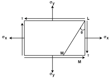
Fig: 2
Locate point P and Q, OP =  and OQ =
Locate point R ( and S (
 )
)
Joint RS intersecting the x-axis at point C
 CP = CQ =

Radius of circle, R = 
The circle intersects abscissa at point A and B shear stress is zero.
1. Stress at a point:
If you deal with a factor as an infinitely small dice, it's far apparent that a dice has six faces, or 3 pairs of planes as faces. It is simplest vital to recollect 3 faces, as the alternative 3 parallel faces are same in natures.
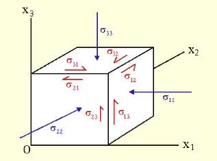
Fig: 3
As proven within side the diagram the pressure on every face may be proven in phrases of three separate pressure vectors, and the stresses skilled may be expressed in nine pressure or stress vectors.
2. Stress on a plane:
When stress is carried out to a plane, it could be expressed in phrases of 1 regular pressure (the pressure performing perpendicular to the plane), and shear stresses (the pressure performing parallel to the plane) as formerly mentioned, simplification of the hassle is required. The plane version works properly whilst best thinking about a unique plane. This may be taken one step in addition to expect that the pressure at an unmarried factor desires to be calculated, because the pressure in the course of an extent can vary. To calculate the pressure at a factor we take the simplification that a factor is in reality an infinitely small cube, and that is dealt with within side the subsequent section.
Key takeaway:
- If you deal with a factor as an infinitely small dice, it's far apparent that a dice has six faces, or 3 pairs of planes as faces
- The plane version works properly whilst best thinking about a unique plane
- This may be taken one step in addition to expect that the pressure at an unmarried factor desires to be calculated, because the pressure in the course of an extent can vary
We have studied the effect of simple stresses which were either normal or tangential acting on particular plane only.
Most of cases on actual member, more complex condition of stresses are developed.
We study the analytical and graphical method to find the stresses acting on an inclined plane of the member subjected combined stresses.
The plane on which the normal stress or the shear stress reaches their maximum intensity has particularly significant on the materials.
1. Concept Principal Plane:
The plane on which only normal stresses acts and no shear stress is called principal plane.
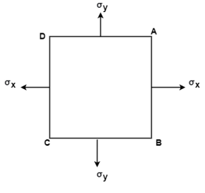
Fig: 4
The plane AB, BC, CD and AD as shown in fig carries only normal stress and no shear stress. These planes are called as Principal planes.
2. Principal stress:
The magnitude of normal stress acting on the principal plane is called as principal stress.
3. Major Principal stress:
- It is maximum value of normal stress acting on the principal plane.
- It is the maximum intensity of direct stress.
4. Minor Principal Stress:
- It is minimum value of normal stress acting on the principal plane.
- It is the minimum intensity of direct stress.
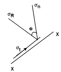
Fig: 5
5. Major Principal Plane:
- A plane which carries major principal stresses is called as major principal plane.
6. Minor Principal Plane:
- A plane which carries the minor principal stress is called minor principal plane
Numericals:
Q. The intensity of the resultant stress, on a plane AB at a point in a material under stress is 80  /
/ and is inclined at
  to the normal to that plane. The normal components of stress on another plane BC, at right angles to the plane AB is 60 N/mm2 as shown in the Fig. Determine the following:
(i) The resultant stress on the plane BC.
(ii) The principal stresses and their directions.
(iii) The maximum shear stress and their planes.
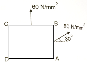
Fig: 6
Given:


Resultant stress on BC
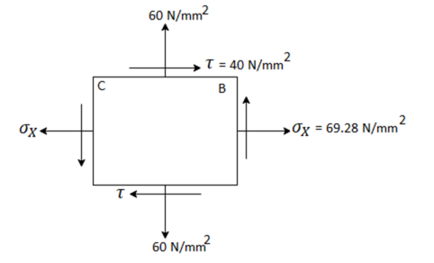
Fig:7

Principle stress


Directions of principle planes,


Maximum shear stress

Plane of maximum shear stress


Q. An element in a two-dimensional stress system is subjected to normal stress intensity of  tensile along X-direction and
  compressive along Y-axis and shear intensity
  Determine the planes of zero shear and maximum shear. Also find the normal and shear stress intensity on these planes.
Given:


To find: 
(i) Plane of zero shear stress 


Location of principle


(ii) Plane of maximum shear stress


(iii) Normal Stress

For 


For 
(iv) Shear stress or tangential stress  and 100.9°

Q. A rectangular block of a material is subjected to a tensile stress of 100 N/mm2 on one plane and a tensile stress of 50 N/mm2 on a plane at right angles, together with shear stresses of 60N/mm2 on the faces.Find1) The direction of principal planes 2)The magnitude of principal stresses 3) The magnitude of greatest shear test 4) The location of plane containing maximum shear stress.
Solution:
Given

Case I. Direction of principle plane


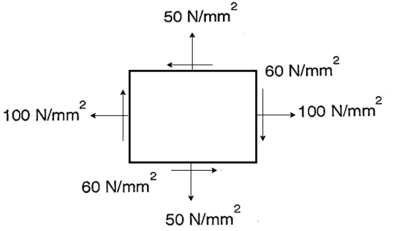
Fig:8
Case II: Magnitude of principal stress


Case 3: Magnitude of a greatest shear stress
 max=
max= =
= =65N/mm2
Case IV: Location of plane containing maximum shear

Q. At a certain point in an elastic material, normal stresses of 96 MPa tensile and 75 MPa compressive are acting on planes at right angle to each other. The greater principal stress in the material is limited to 120 MPa. To what shearing stress may the material be subjected to on the given planes, and what will be the maximum shearing stress at that point.
Given:


To find: and 
(i) Shear stress


Squaring both side

(2) Maximum shear stress

Q. At a point material, the values of normal stress across two angles to each other are 80 MPa and 32 MPa ,both tensile and there is a shear stress of 32MPa an shown in the Fig. Determine-
1) Stress component on the plane at  anticlockwise.
2) The Principal stress and their direction
3) The maximum shear stress
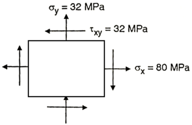
Fig:9
Given: 
To find: 
Principal stress


Major principal stress 
Minor principal stress 
Location of principal plane


Maximum shear stress 
Location of plane of maximum shear plane


Q. For the stress condition on an element as shown Fig.determine the principle planes and stresses. Also determine the maximum shear stress and the planes on which they act.
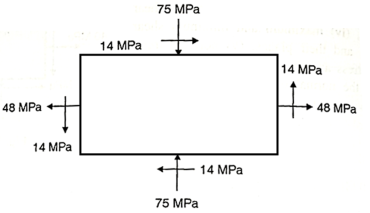
Fig:10
Given: 
To find: 
(i) Location of principal plane


Principle stress


Maximum Principle stress 
Minimum Principle stress 
(iii) Maximum shear stress

(iv) Location of shear plane


Q. For the stress condition on an element as shown in Fig., determine the principal planes and stresses. Also determine the maximum shear stress anad the planes on which they act:
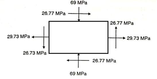
Fig:11
Given: 
To find: 
Principal planes


Principle stress


Maximum principal stress 
Minimum principal stress 
Maximum shear stress 
Location of plane of shear stress


Q. Resultant stresses on two mutually perpendicular planes are as shown in Fig. Calculate principal stresses and their direction.
To find: 
From the given Fig.(a) stress on the plane

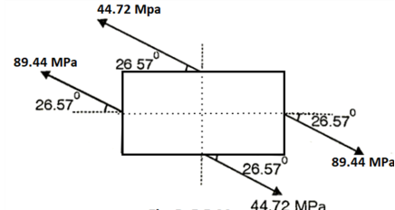
Fig:12


 Location of principal plane


 Principal stress

Major principal stress 
Minor principal stress 
Q. Direct stresses of 160N/m tensile and 120
  compressive exists on two perpendicular planes at a certain pint in a body. They are also accompanied by shear stresses on the planes. The greatest principal stress at the point due to there is 200
(i) What must be magnitude of shearing stresses on the two planes?
(ii) What will be the maximum shearing stress at the point.
Given:

To find: i) (ii) 
Major principal stress, 


Squaring both side, 

Maximum shear stress,

(ii) Alternative method for 
Minor principal stress


Maximum shearing stress,

Q. At a point in a material under stress, intensity of the resultant stresses on a certain plane is  (tensile), inclined at
  to the normal of that plane. The stress on a plane right angle to it has a normal tensile component of 3
 . Find
(i) The resultant stress on the second plane
(ii) The principle plane and stresses
(iii) The plane of maximum shear stress and its intensity.
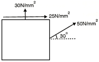
Fig:13
Given: 

To find: Result stress on the second plane, principal stress and maximum shear stress.
(i) Resultant stress on second plane

 Resultant stress,
(ii) Location of principle plane:


 Principle stress


 Major principle stress
 Minor principle stress
(iii) Maximum shear stress

Location of plane of maximum shear stress,


Q. A plane element in a body is subjected to a tensile normal stressof 25MPa in X-direction and anticlockwise shear stress 100 MPA. Calculate the stresses on a plane inclined at 20° clockwise to X-axis.
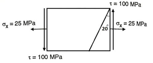
Fig:14
Given:


To find: 
Normal stress 
 =12.5+9.576-64.28

Tangential stress


Resultant stress


Angle of obliquity

Q. For the given state of plane strain  . Determine
(i) Principle axis of strains
(ii) Principle strains
(iii) Maximum shearing strain
Given:

To find θ, 
(i) Principal axis of strain


(ii) Principal axis of strain


(iii) Maximum shear strain

Key takeaway:
- It is maximum value of normal stress acting on the principal plane.
- It is the maximum intensity of direct stress.
- A plane which carries major principal stresses is called as major principal plane.
A graphical method of finding of principle stresses normal longitudinal and resultant stresses with the help of circle is called as Mohr’s circle method
In this method direct stress ( ) is represent on x axis and shear stress (
 ) on y axis
Tensile direct stress is taken on positive x- axis and compressive direct stress on negative x- axis
Shear stress produced clockwise moment in the elements is consider positive and anticlockwise moment is negative
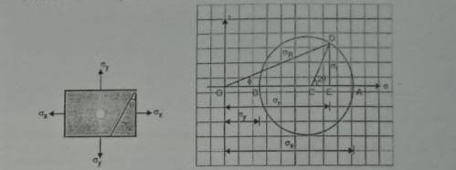
Fig:15
Centre of circle is found by 
Where  are dierect stresses
Radius of circle 
In Mohr’s circle the angle between the planes will be represented by double the angle
For example, when circle draw from center c with radius R it cuts x- axis at point A and B where shear stress is zero
The angle between AOB is equal to 180 degree
But angle between two principal plans is 90 degree
At point A and B since, there is no shear stress OA and OB represents principal stresses
Radius of circle indicates the maximum shear stress which is located at 2 w.r.to x- axis i.e., at 2 x 45 degree = 90 degree
Numericals:
Q. At a point strained material, the principal stresses are 180 MPa and 60MPa respectively. The plane inclined at 20 with major principal plane, find the normal tangential and resultant stress on this plane, using Mohr’s cycle method.
Given: 
To find: 
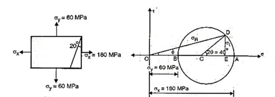
Fig:16
Step 1: Select origin O, the rectangular axis x and y through O represents and axis.
Step 2: Select suitable scale, take 
Step 3: Take  and
and  from O
Step 4: Take AB as a diameter of Mohr’s cycle, bisect OA at C, Draw a circle radius AC or CB from C.
Step 5: Draw a line CD at angle  counter clockwise with x-axis.
Step 6: Draw a perpendicular from D to x-axis, also joint OD.
Step 7: OE represents normal stress  DE represents tangential stress and resultant stress represents by OD.
 From Mohr’s circle,


Q. The principle stresses at a point across two perpendicular plane are 80 MPa (tensile) and 40MPa (compressive). Find the normal, tangential and resultant stress on a plane inclined at 20 to the axis of major principle plane.
Given:


To find: 
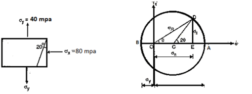
Fig:17
Step 1: Select any point O and draw a horizontal line OA.
Step 2: Select suitable scale, take  take OA=8cm toward right and OB=4cm toward left of O.
Step 3: Take AB as a diameter of cycle. And take C as a centre of a circle. Draw a circle of radius AC or CB.
Step 4: Draw a line CD from C making an angle 2θ with horizontal OA
Step 5: Draw a perpendicular from D to line OA. Also join OD represent resultant stress, OE represent normal stress and DE represent tangential stress.
Step 6:  DOE represents the angle of obliquity.
From Mohr’s cycle
Normal stress
Tangential stress
Resultant stress
Obliquity
Key takeaway:
- Tensile direct stress is taken on positive x- axis and compressive direct stress on negative x- axis
- The angle between AOB is equal to 180 degree
- But angle between two principal plans is 90 degree
Once we circulate into dimensions, matters are a chunk extra complicated. There is a limitless range of in another way orientated cloth strains in a surface. Lines with unique orientations will display unique values of s and γ
The maximum intuitive manner to symbolize stress in 2D is to assume a circle earlier than deformation, and to study its form after deformation. In general (for homogeneous stress) the circle turns into an ellipse - the stress ellipse.
The stress ellipse is the made of a finite stress carried out to a circle of unit radius. It is an ellipse whose radius is proportional to the stretch s in any direction.
A deformed round item has the equal form (all even though not, strictly, the equal size) because the stress ellipse.
Application:
The application of the stress ellipsoid is to be seemed handiest as a convenient way wherein a given structural circumstance is made understandable.
The stress ellipsoid is a strong or a 3-dimensional conception, and its application must be made with that reality in mind Intersecting shear planes in go segment imply simpler upward relief than lateral, a circumstance that can exist at intensity in addition to on the surface
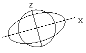
Fig:18
Key takeaway:
1. Once we circulate into dimensions, matters are a chunk extra complicated. There is a limitless range of in another way orientated cloth strains in a surface.
2. The application of the stress ellipsoid is to be seemed handiest as a convenient way wherein a given structural circumstance is made understandable.
A two -dimensional pressure (stress) system is one wherein the stresses at any factor in a frame act within side the same aircraft. Consider a skinny square block of material, abcd, faces of which can be parallel to the xy-plane
Stress within side the Lithosphere – isostatic equilibrium (or Archimedes principle). In the mantle below the lithosphere, stress ought to be equal. Thus, the burden of the overlying rocks ought to be equal. The thick low density crust floats better at the as lithosphere. The continental crust is be neat anxiety due to the fact the pressure at any given intensity in the crust is better than within side the adjoining mantle. The low-density crust needs to unfold out over the mantle.
Thrust Sheets - Shear pressure consequences from the frictional resistance to movement at the fault. Shear pressure is associated with the burden of overburden and the coefficient of friction.
Stress in Two Dimensions - State of pressure in 2D may be defined through ordinary stresses and 1 shear pressure (the 2 shear stresses ought to be equal or the frame might rotate).
Normal and shear pressure on any arbitrary aircraft may be decided from the 2 ordinary stresses (x- and y-axes) and one shear pressure and the attitude among the ordinary to the plane and the x-axis.
Principal axes of pressure are ordinary to planes of 0 shear pressure. The important axes are orthogonal.
Maximum shear pressure is 45° from the important pressure direction. Maximum shear pressure is one 1/2 of the difference of the important stresses.
Principal Strain:
Maximum and minimal normal strain feasible for a particular factor on a structural element
Shear strain is zero on the orientation where major strain occurs.
Principle strain is also known as st. Vanant theory
The principal strain causes that the material subjected to conjugate stresses will falls when the maximum principal strain in the reaches the value of strain at yield point in a simple tensile test at materials
Principal axis of Strain
Principal stress axes in a strained material, 3 jointly perpendicular axes (special X, Y, and Z) which can be parallel to the instructions of greatest, intermediate, and least elongation, and which describe the kingdom of stress at any specific point.
The maximum intuitive manner to represent pressure strain in 2D is to assume a circle before deformation and to appearance at its form after deformation. In general (for homogeneous pressure) the circle turns into an ellipse - the pressure ellipse. The pressure or strain ellipse is the fabricated from a finite pressure implemented to a circle of unit radius.
- Circle of strain:
A graphical method of finding of principle stresses normal longitudinal and resultant stresses with the help of circle is called as Mohr’s circle method
In this method direct stress ( ) is represent on x axis and shear stress (
 ) on y axis
Tensile direct stress is taken on positive x- axis and compressive direct stress on negative x- axis
Shear stress produced clockwise moment in the elements is consider positive and anticlockwise moment is negative
Centre of circle is found by 
Where  is direct stress
Radius of circle 
In Mohr’s circle the angle between the planes will be represented by double the angle
For example, when circle draw from center c with radius R it cuts x- axis at point A and B where shear stress is zero
The angle between AOB is equal to 180 degree
But angle between two principal plans is 90 degree
At point A and B since, there is no shear stress OA and OB represents principal stresses
Radius of circle indicates the maximum shear stress which is located at 2 w.r.to x- axis i.e., at 2 x 45 degree = 90 degree
2. Ellipse of strain:
Once we circulate into dimensions, matters are a chunk extra complicated. There is a limitless range of in another way orientated cloth strains in a surface.
Lines with unique orientations will display unique values of s and γ.
The maximum intuitive manner to symbolize stress in 2D is to assume a circle earlier than deformation, and to study its form after deformation.
In general (for homogeneous stress) the circle turns into an ellipse - the stress ellipse.
The stress ellipse is the made of a finite stress carried out to a circle of unit radius.
It is an ellipse whose radius is proportional to the stretch s in any direction.
A deformed round item has the equal form (all even though not, strictly, the equal size) because the stress ellipse.
Key takeaway:
- A graphical method of finding of principle stresses normal longitudinal and resultant stresses with the help of circle is called as Mohr’s circle method
- In this method direct stress (
 ) is represent on x axis and shear stress (
 ) on y axis
 - Tensile direct stress is taken on positive x- axis and compressive direct stress on negative x- axis
- The relationship between Young’s modulus (E), rigidity modulus (G) and Poisson’s ratio (µ) is expressed as:

- The relationship between Young’s modulus (E), bulk modulus (K) and Poisson’s ratio (µ) is expressed as:

- Young’s modulus can be expressed in terms of bulk modulus (K) and rigidity modulus (G) as:

- Poisson’s ratio can be expressed in terms of bulk modulus (K) and rigidity modulus (G) as:

References:
- Timoshenko, S. And Young, D. H., “Elements of Strength of Materials”, DVNC, New York USA.
- Kazmi, S. M. A., “Solid Mechanics” TMH, Delhi, India.
- Hibbeler, R. C. Mechanics of Materials. 6th ed. East Rutherford, NJ: Pearson Prentice Hall, 2004
- Crandall, S. H., N. C. Dahl, and T. J. Lardner. An Introduction to the Mechanics of Solids 2nd ed. New York, NY: McGraw Hill, 1979
- Laboratory Manual of Testing Materials - William Kendrick Hall
- Mechanics of Materials - Ferdinand P. Beer, E. Russel Jhonston Jr., John T. DEwolf – TMH 2002.