Unit - 4
Flexural Stresses
When the beam is subjected to a constant bending moment no shear stresses are induced in that portion of beam is called as simple bending or pure bending.
A simply supported beam ABCD subjected to two equal point load w at equal distance ‘a’ from each support.
In this chapter we are considering the beam is subjected to pure bending only. i.e., shear force neglected.
In shear force diagram the shear force between portion BC is zero.
In bending moment diagram the bending moment between portions BC is constant. The portion BC is said to be under pure bending.

Fig:1

Fig:2
1. The material of beam is homogeneous and isotropic. (Isotropic means having the properties same in all direction.)
2. The beam is straight before loading.
3. The beam is uniform cross section throughout its length.
4. Transverse section which is plane before loading remains plan even after loading.
5. The material is elastic and hooks law is applicable.
6. The effect of shear is neglected therefore the analysis is meant for pure bending.
7. The modulus of elasticity E has same value in tension and compression.
8. Each layer is free to expand or compact having no influence in the neighboring layers for their extraction and contraction.
9. The beam is initially straight and all longitudinal filaments bend into circular area with a common center of curvature.
Derivation of flexural formula:

Fig.3: Before Bending
Consider any two normal sections AB and CD of a beam for a small length ‘dx’ apart as shown in fig. After the application of the transverse loading on the beam will be bends A B
Let AB and CD intersect each other at ‘O’

Fig.4: After Bending
Let,
R = Radius of curvature of the neutral layer EF
θ = subtended angle at ‘O’
Consider a layer GH at a distance y from neutral axis
Stain in layer GH due to bending
e = change in length/ original length
 = GH-GH
GH
But GH = EF
From Fig.
Length of arc = subtended angle x radius
Original length EF = EF = R θ
Length of layer GH = (R + y) θ
Change in length = GH - GH = (R + y) Θ - R θ


 ……. (i)
By definition, modulus of elasticity, ……. (ii)
 …….. (iii)
From equation (i) and (ii)


Since E and R are constant, the stress is directly proportional to the distance from neutral axis (N, A)
Now consider cross section of the beam consider an elementary strip at ‘y’ from N.A. And area of the strip ‘dA’

Fig:5
Force on the strip = stress on the strip x area on the strip


Moment of this force about N.A


Total moment of whole section about N.A

But  = Moment of inertia about neutral axis


From equation (iii) and (iv) we get,

This is known as bending formula or flexural formula
Key takeaway:
1. The beam is straight before loading.
2. The beam is uniform cross section throughout its length.
3. Transverse section which is plane before loading remains plan even after loading.
4. The material is elastic and hooks law is applicable.
5. The effect of shear is neglected therefore the analysis is meant for pure bending.
In the beam a layer which does not change its original length even after bending is called as neutral layer or neutral axis
The bending stress is always zero at the neutral axis
Neutral axis is the line of intersection of the neutral layer with any normal section of the beam
It will be proved that the neutral axis of the beam passes through the centroid of the section
1. Determination of bending stresses – section modulus of rectangular:
Example1]
Maximum bending moment of simply supported beam of 10 KNM. The cross section of the beam is as shown in fig. Find the maximum bending stress in tension and compression.
Diagram:
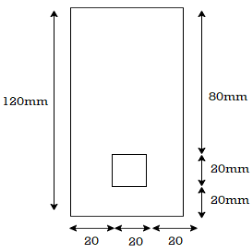
Fig:6
Solution
Given:
M = 10 KNM = 10 x 104 N.mm
Beam = simply supported
To find: 
Strep 1) Position of neutral axis

A1 = 60 x 120 = 7200 mm2
A2 = 20x 20 = 400 mm2
y1 = 120/2 = 60 mm
y2 = 20/2 + 20 = 30 mm


Since, the beam is simply supported,
yt = y = 61.76mm
yc = 120 –y -= 120 – 61.76 = 58.24 mm
Step 2) moment of inertia
Ixx = Ixx1 – Ixx2
[IG1 + A1h12] – [IG2 + A2h22]

= 8.662 x 10⁶ – o.4168 x 106
= 8.245 x 106 mm4
2. Determination of bending stresses – section modulus of circular:
Example:
A beam is circular section of diameter d and length L is a simply supported at ends carries central point load W- 2KN L= 4m what should be the value of diameter d so that maximum stresses in beam does not exceed 80 Mpa

Fig:7

Fig:8
Solution:
Given:
L= 4 m
W= 2 KN
To find:
Bending moment
M= WL/4
= 2x 4 /4
= 2 KN.m
Using bending moment formula


3. Determination of bending stresses – section modulus of I angle:
Example1]
A beam of span 4 m carries a udl 15 KN/M the cross section of the beam as shown in fig. Find maximum stress induced bending stress diagram.
Diagram:
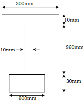
Fig:9
Solution:
Given:
L = 4m
W = 15 KN/M
To find: 
Maximum bending moments


Position neutral axis:

A1 = 200 x 30 = 6000 mm2
A2 = 10 x 960 = 9600 mm2
A3 = 300 x 10 = 3000mm2
y1 = 30/2 = 15 mm
y2 = 960/2 +30 = 510 mm
y3 = 10/2 + 960+30 = 995 mm


Moment of inertia
I = Ixx1+ Ixx2+Ixx3
= [Ix1+A1h12] + [Ix2+A2h22] + [Ix3+A3h32]

= 2.7896 x 103 mm4
Depth of neutral axis from top
yc = 1000-y1 = 1000-428.55
Ymax. 571.45mm
Maximum bending stress


The maximum stress induce in the bean section is 6.15 mpa
4. Determination of bending stresses – section modulus of T angle
Example 1]
A simply supported beam of 5 m span carries uniformly distributed load of 2 KN/M over span cross section of the beam is shown in fig. Find maximum bending stress induced in beam
Diagram

Fig:10
Solution:
Given:
L =5m
Udl w = 2 KN/M
To find:
Position of neutral axis
A1 = 140 x 10 = 1400 mm2
A2 = 100x10 = 1000mm2
y1 = 140/2 = 70mm
y2 = 140+10/2 = 145mm


y= 101.25mm
Moment of Inertia
I = Ixx1 + Ixx2

= 5.576x104 mm4
Find moment
WL2/2 = 2x52/2 = 6.25KN-m
Since, the beam is simply supported tension induced below N.A
y= yt= 101.25mm
Yc= 150-101.25= 48.75 mm
Maximum bending stress using flexure formula


The maximum bending stress induced in the beam is 113.5 N/mm2
5. Determination of bending stresses – section modulus of channel section:
Example:
A CI beam of c section with top flange 150 mm x 15mm bottom flange 200mmx20mm and web 15mmx 200 mm is supported over a span of them it the permissible stresses are 120 mpa compression what udl can be safety applied on beam. What will be tensile stress in the beam
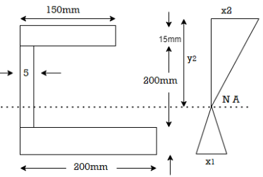
Fig:11
Solution
Given:

To find:
Safe udl w and tensile stress
Position of neutral axis
A1 = 200 x 20 = 4000 mm2
A2 = 200 x 15 = 3000 mm2
A3 = 15 x 150 = 2250 mm2
y1 = 10 mm
y2= 120 mm
y3 = 227.5 mm

Moment of inertia
Ixx= Ixx1+Ixx2
= 
Ixx = 80.33 x 106 mm4
Position of extreme fiber from NA
y= yt = 98.5 mm
Yc = 235-98.5 = 136.5 mm
Bending formula


Maximum bending moment = wl2/8 = 15.7 kN/m
Tensile stress:


Simply supported beam or Cantilever beam
Step1) Preliminary dimension of beam
- Effective span of beam
c/c dist. Of support
Clear span + effective depth (d)
b. Effective Depth of beam
The effective depth of beam between
Deff. = leff. /15 to leff/10
Assuming suitable cover and bar dia. Calculating the overall depth
Calculating the overall depth
D = deff. + d’ (effective cover)

General bar dia. Use for beam is from 12mm to 20 mm
Step2) Load calculation and Design moments
- Load calculation:
- Self wt of beam =

- Load from slab= (DL+LL+FF)
For trapezoidal loading = 
For triangular loading = Wu. Leff. /3
c. Load from wall = 20x thickness of wall x ht. Of wall
d. Live load
B. Design moment:
For simply supported beam mu= Wu. Leff.2/8
For cantilever beam mu = Wu l/2
C. Design of shear force:
Simply supported beam = wl/2
Cantilever beam = wl
Step 3) Check for depth

Step4) Check for Steel


Singly reinforced beam:
For doubly r/f beam section find our Ast1 and Ast2 for Mu1 and Mu2
Ast1 = Mu1/(0.87fy(d-0.42xu))
Ast2 = Mu2/ (0.87 fy (d-dc’)
Hence calculate the Astprov. Is equal to
Ast provide= ast x no. Of bars
Step 5) Check for width:
If N is no. Of bars
Breq. = 2c1+N + (N-1) c2
Where,
c1 = clear cover + dia. Of stirrups
c2 =  or maximum size of agg. + 5mm
Step 6) Check for deflection
Step 7) Check for shear
Step 8) Check for development length
Key takeaway:
- Preliminary dimension of beam
- Load calculation and Design moments
- Check for depth
- Check for steel
- Check for width
- Check for deflection
- Check for shear
- Check for development length
Numericals:
Q. A thin strip 0.5 mm thick and 3.14 m long is bent into a circular shape. Determine the maximum bending stress induced. Take E=200 GPa.
Given t=0.5 mm, L=3.14 m, 
Diameter of bent 

Radius R=500mm

Bending formula 

 Maximum bending stress induced in thin strip is
Q. A high strength steel band saw, 20 mm wide by 0.8 mm thick runs over a pulley 600 mm in diameter, what maximum flexural stress is developed? What minimum diameter pulley can be used without exceeding a flexural stress of  ? Take
Given:
B=20mm, t=0.8mm
D=600mm,

Case (i)
Maximum stress developed in the stress band saw
Position of N.A
Moment of inertia
Flexural formula 
Maximum stress


Case (ii)
Minimum diameter of pulley without exceeding stress 400MPa


The diameter of pulley is 400 mm
Q. A rectangular beam 300 deep is simply supported over a span of 4m. What udl the beam may carry if the bending stress is not to exceed 120 MPa? Take 
Given d=300mm
To find w
Position of Neutral axis 
Moment of Resistance by using bending formula


Bending moment due to loading


 Safe udl that the beam can carry is 3.2 kN/m
Q. A beam is of triangular section base 60 mm and height 120 mm with a hole of radius 10 mm as shown in Fig. If the maximum stress in the beam section not to exceed 100  . Determine the maximum bending moment on beam.
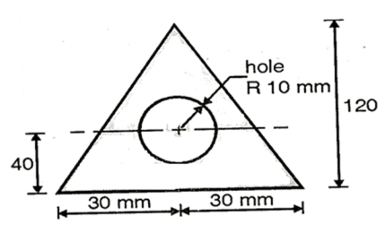
Fig:12
Given: Radius of hole R=10m
Base b=60mm, eight h=120 mm
Maximum permissible stress in beam 
To find Bending moment ‘M’:
Position of neutral axis:
Since the C>G of circular hole is at C.G of triangle

Moment of inertia
Maximum distance of neutral axis from extreme end

Moment of inertia 
Maximum distance of neutral axis from extreme end


By bending formula


Hence the maximum bending moment is M=3.59 kNm
Q. A cast iron beam 2.75 m long has one support at left end A and other support at B which is at 0.75 m from end C as shown in Fig. The beam is of T section consisting of a top flange 150mm×20mm and a web of 20 mm wide and 80mm deep. If the tensile and compressive stresses are not to exceed 40 N/ and
and  respectively, find the safe concentrated load W that can be applied at the right end of the beam.
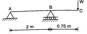
Fig:13
From given beam, only hogging moment produces the section 
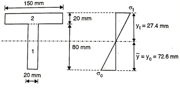
Fig.14: Shear Distribution diagram
Position of neutral axis:


Moment of inertia


Maximum permissible stress in tension and compression should not exceed 40 N and 70 N/mm^2 respectively by stress distribution diagram.
By stress distribution diagram

Let 

Using bending formula


Equating value of BM to MR, we get,


Q. A cast iron beam section is an I section with top flange 80 mm× 20 mm, bottom flange 160 mm×40 mm and web 200 mm deep and 20 mm thick. The beam is simply supported on a span of 5 m. If the tensile stress is not to exceed 20 N/ , find the safe u.d.l which the beam can carry and also maximum compressive stress.
Given 
To find: udl and 

Fig:15
Position of neutral axis,


Moment of inertia
 +
+ +
+


For simply supported beam, tension induced below neutral axis

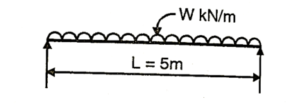
Fig:16
Moment of Resistance


Safe udl

Compressive stress

Q. A beam of T-section 4m long carries a uniformly distributed load w per meter run throughout its length. The beam is simply supported at its ends. The T section is 20×10×1.2 cm i.e., web is 18.8×1.2 cm and flange is 10×1.2 cm. What is the maximum value of w so that the stress in the section does not exceed 60 MPa.
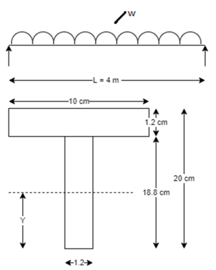
Fig:17
Given L=4m, f=60 N/m
To find w=?
Position of neutral axis


Moment of inertia


Maximum bending moment

Uniformly flexural formula,


Q. A symmetric I section is 150 wide and 200 deep. The flange thickness and web thickness is 10mm. This section is used for cantilever beam having a span of 3 m and subjected to uniformly distributed load. Fid the maximum u.d.l that can be supported if E=200 GPa and maximum allowable stress is 180 MPa.
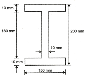
Fig:18
Given: Section – Symmetrical I
Width b=150 mm
Deep d=200 mm
Flange thickness t=10mm
Span L=3 m
Young’s modulus W=200 GPa=200
Maximum allowable stress 
To find Maximum u.d.l
Position of neutral axis

Moment of inertia

Flexural formula


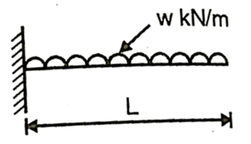
Fig:19
Maximum u.d.l that can be supported by cantilever beam


Q. A cast iron beam of cross-section resembling a rail is symmetrical about a vertical axis in cross-section. Total depth =180 mm, Top flange=80 mm×20 mm, Bottom flange and Web =120 mm×20 mm. If the maximum allowable stress in tension is 30 MN/m
 and that of compression is 30 MN/m
 , find moment of resistance of the cross-section.

Fig:20
Given: 

To find: M
Position of neutral axis,


Moment of inertia


Since the beam is simply supported, tension induced below neutral axis


Moment of resistance


Q. The cross-section of a simply supported beam of 5 m span is as shown in fig. If permissible stresses are 100 MPa in compression and 40 MPa in tension. Find safe UDL the beam can carry.

Fig:21
Given: L=5m 
To find w
Position of neutral axis


Moment of inertia


Since the beam is simply supported, tension included below N.A


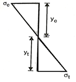
Fig:22
Check for safe stress

Let 


Using flexure formula


Safe udl


Q. Fig. Shows a rectangular section of a beam 100 mm wide and 200 mm deep. If the maximum bending stress is 80 MPa, determine (i) total force on the shaded area, (ii) moment of this force about NA.
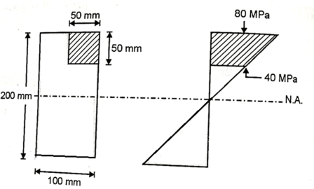
Fig:23
Total force on shaded area = Average stress × Area


Position of centroid of shaded portion from N.A


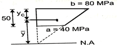
Fig:24
Moment about N.A M = F× 


Alternative method:


Moment of inertia of shaded portion about N.A

Moment about N.A 


Q. A beam of circular section of diameter d and length L is a simply supported at ends, carries central point load W =2kN, l=4m. What should be the value of diameter d, so that maximum stresses in beam does not exceed 80MPa.
Given L=4m;W=2 Kn;
To find: Diameter d
Bending moment:
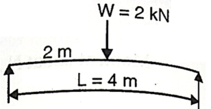
Fig:25

Using bending formula 


 Diameter of beam is 63.38 mm0
Q. A simply support beam 4 m span carrying udl of 5kN/m permissible stress in the material of beam is 15  . Design the section of beam if depth to width ratio is 2.
Given d=2b;b=0.5 d
W=5kN/mL=4m

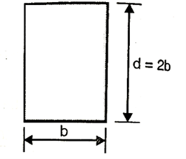
Fig:26
To find: Width ‘b’ and depth ‘d’
Bending moment for simply support beam 
Moment of inertia 
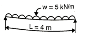
Fig:27
By bending formula


∴The section of beam is 100×200mm
Q. A timber beam is of square section with a circular hole as shown in fig. Side of the squarer 2a diameter of the whole a. Timber beam is simply supported over a span of 8m. A load of 1 kN is applied at center of beam. What is dimension ‘a’ is if maximum bending stress in beam is not exceed 
Given: L=8m;W=1Kn;
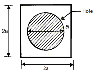
Fig:28
To find value of ‘a’
Bending moment
Position at neutral axis 
Moment of inertia 
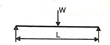
Fig:29
Bending formula


Hence the side of the beam is 54 mm
Q. A simply supported beam has square cross section throughout its length the side of square is a. The section carrying bending moment M. Calculate maximum bending stress.
(i) Side of square is kept vertical.
(ii) Diagonal of square is kept horizontal.
Given:
 side =a
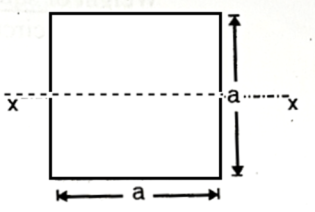
Fig:30
To find Maximum bending stress for both cases.
Case(i)
Side of square is kept vertical

Moment of inertia

Bending stress 
Case(ii)Diagonal of square is kept vertical.
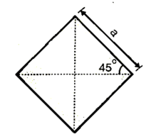
Fig:31
Depth of neutral axis

Moment of inertia 
Bending stress 
References:
- Timoshenko, S. And Young, D. H., “Elements of Strength of Materials”, DVNC, New York USA.
- Kazmi, S. M. A., “Solid Mechanics” TMH, Delhi, India.
- Hibbeler, R. C. Mechanics of Materials. 6th ed. East Rutherford, NJ: Pearson Prentice Hall, 2004
- Crandall, S. H., N. C. Dahl, and T. J. Lardner. An Introduction to the Mechanics of Solids 2nd ed. New York, NY: McGraw Hill, 1979
- Laboratory Manual of Testing Materials - William Kendrick Hall
- Mechanics of Materials - Ferdinand P. Beer, E. Russel Jhonston Jr., John T. DEwolf – TMH 2002.