Unit - 5
Shear Stresses
1. Shear stresses:
The shear force at the cross section of a beam is defined as the algebraic sum of all the unbalanced vertical forces either left or right of the section.
SF = (∑ Fy) L = (∑ Fy) R
Sign convention for shear force:
An upward force to the left of section or downward force to the right of a section will be considered as a positive shear force.
When the force is downward to the left side of section and upward on the right of a section, will be considered as a negative shear force.
2. Derivation of formula
Consider a small portion ABCD of length dx of a beam with bending moment varying from m to m=dm due to udl over its length dx
The distribution of compressive stresses due to bending moment shown in fig
Let
M = bending moment at AB
M + dM = bending moment at CD
F = shear force at AB
F+ dF = shear force at CD
Consider element strip EF at a distance y from the neutral axis as shown in fig.

Fig:1
Let
σ = bending stress across AB at a distance y from neutral axis
σ + d σ = bending stress across
I = moment of inertia
By using flexural formula

On face AB, 
On face CD, 
Face acting across AB 
Similarly, force acting across CD, 
Net unbalanced force on the strip

The load unbalanced force F above neutral axis can be found out by integrating from 0 to d/2


But ∫ y x dA= first moment of area under consideration from neutral axis= Ay
F = dM/ I x Ax y
This unbalanced force is balanced by a shearing stress 𝜏 acting along the length dx and width b,
Shear stress = shear force/ shear area


But 

Where,
S = shear force at the section under consideration
A = area above or below the layer under consideration
y = distance of centroid of area under consideration from neutral axis
b = width at the layer under consideration
I = moment of inertia of the section.
Key takeaway:
- The shear force at the cross section of a beam is defined as the algebraic sum of all the unbalanced vertical forces either left or right of the section.
- An upward force to the left of section or downward force to the right of a section will be considered as a positive shear force.
- When the force is downward to the left side of section and upward on the right of a section, will be considered as a negative shear force.
1. Shear stress distribution over a circular section:
Consider a circular section of diameter d as shown in fig.
Diagram
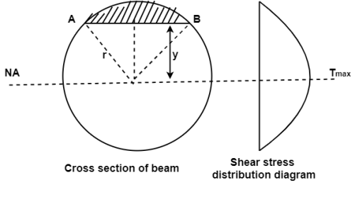
Fig:2
The shear stress on a layer AB at a distance is given as,

Width of strip AB in a circular section

Where, r= radius of circular section
Area of shaded strip =
Moment of area about neutral axis =
The moment of whole shaded area about neutral axis

But 

Again, 
Squaring both side
2b db = 4(-2y) dy

Substituting the value of y. Dy in equation (i)

We know that, when y= r. And b = 0
The limit of integration may be changed from y to r, from b to 0 in equation (i)


Now substituting Ay in shear stress formula


Observations from above equation
From Equation (iii) shear stress 𝜏 increases as y decreases
At y = 𝜏 𝜏 = 0
At y = 0 𝜏 is maximum

Put r= d/2

Put I = 𝛑/64 d4


Therefore,


2. Shear stress distribution over a rectangular section:
Consider a beam of a rectangular section of width b and depth d as shown in fig.

Fig:3
Shear stress at any layer CD of beam at a distance y from the neutral axis

Where,
S = shear force at the section
A = Area of beam above y
y = Distance of centroid of shaded area from neutral axis
I = Moment of inertia of the section
b = Width of section CD
Area of shaded portion 
Distance of centroid of area from neutral axis


Moment of inertia 
Shear stress at any layer CD


From above equation we can observe that,
𝜏 increases as y decrease
Variation of 𝜏 is parabolic as the equation in of second degree
When y = d/2, 𝜏 = 0
When y= 0, 𝜏 is maximum
The variation of shear stress across the depth of the beam is parabolic.
Shear Stress
At top and bottom, y= d/2 
At neutral axis, y= 0


Where

3. Shear stress distribution over a triangle section:
Consider a beam of triangular section ABC of base b and height h as shown in fig Shear stress on a layer DE at a distance y from neutral axis.

Consider a section DE at distance x from apex A
Width of the trip DE (say b)
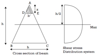
Fig:4
By similarity of triangle


Area of shaded portion ADE

Distance of centroid of area above layer DE

Shear stress at DE


Observation from above equation the variation of shear stress with respect to x is parabolic
At x= 0, 
At bottom x=h, 
At a neutral axis x=2/3 h


For maximum shear stress 
h-2x = 0
x= h/2
Maximum shear stress occurs at h/2 for triangular section


For triangle section maximum shear stress occurs at h/2 and is on neutral axis
4. Shear stress distribution over a T section:
Q. Draw shear stress distribution on a T section with flange 150 x 15 deep and flange 200x 20 wide. The section is symmetric at vertical axis the shear force applied is 110KN
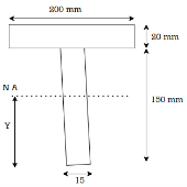
Fig:5
Solution:
Given:
T section
Shear force S= 110 KN
To find: Shear stress distribution
Position of neutral axis

A1= 15x 150= 2250 mm2
y1 = 150/2 = 75 mm
A2 = 200x20 = 4000mm2
y2 = 150+ 10 = 160mm

y = 129.4 mm
Moment of inertia
I = Ixx1+ Ixx2
[
= 14.756x106 mm4
Shear stress at extreme top and bottom is zero
Shear stress at junction
Area above junction A = 200x 20 = 4000mm2
C.G of area above junction wrt.NA
y = (170-129.4)-20/2 = 30.6 mm
Width of junction b1= 200mm and b2 = 15mm


Numericals:
Q. A simply supported beam of span 4 m carries UDL of 80 k/Nm over the entire span. Draw the shear stress distribution diagram at support indicating all important values. Refer Fig.

Fig:6
L=4m, w=80Kn/M
To find:
Position of Neutral Axis


Moment of inertia


Shear force 
Shear stress at junction


Shear stress at Neutral axis

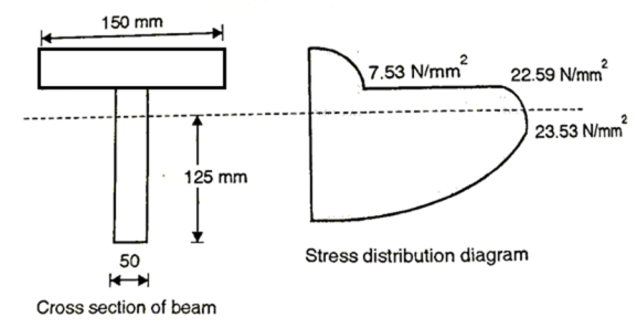
Fig:7
Q. A simply supported beam carries a uniformly distributed load of 30 N/mm over the entire span of 1 m. The cross-section of the beam is a T section, with its top flange of (125×25) mm and web of (175×25) mm. Obtain the maximum shear stress and plot shear stress distribution.
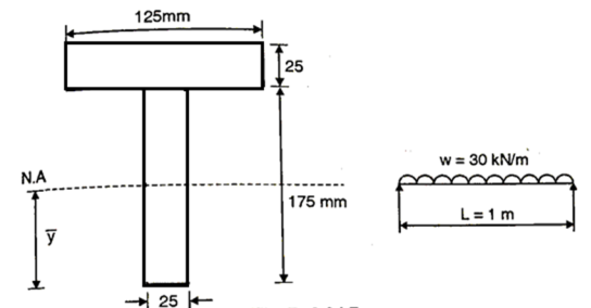
Fig:8
Shear force 
Position of Neutral axis


Moment of inertia


Shear stress at top dayer of flange, =0
Shear stress at junction of flange and web

When 
When 
Shear stress at neutral axis
Consider area below Neutral axis
Consider area below Neutral axis


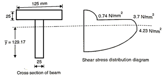
Fig:9
Q. A simply supported beam of span 4 m uses a T section with flange 100×10 deep and web 150×10 wide. The section symmetric about vertical axis. The beam carries two point loads 5kN each placed symmetrically at third point. Find out maximum shear stress in the beam.
Given: T section
Span L=4m
Two point load W=5kN
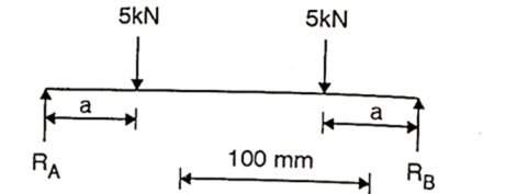
Fig:10
To find:

Fig:11
As loads are placed symmetrically,
Shear force 
Position of neutral axis


Moment of inertia


Maximum shear stress occurs at neutral axis
Area below N.A. A=10×107=1070mm2
Centroidal of area below N.A

Shear stress 

Q. Draw shear stress distribution diagram for cross section of beam shown in Fig. The shear force at section is k N and MI is 1.134 ×108mm4.
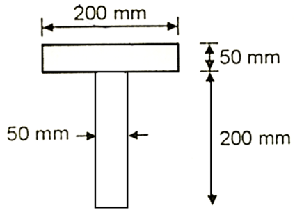
Fig:12
Given:
Shear force S=100kN
Moment of Inertia 
To find: Shear stress distribution
Position of Neutral axis,

Shear stress at Neutral axis.
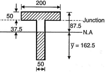
Fig:13

Shear stress at junction of web and flange

 =2.76×
 =11MPa
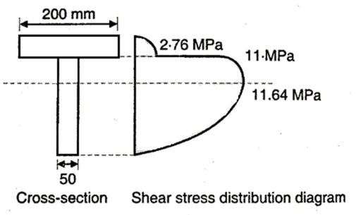
Fig:14
Q. A steel beam of I section,200mm deep and 160 mm wide has16 mm thick flanges and 10 mm thick web. The beam is subjected to a shear force of 200kN. Determine the stress distribution over the beam section if the web of the beam is kept horizontal as shown in Fig.

Fig:15
Solution:
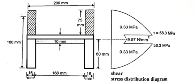
Fig:16
Given: s=200kN
To find: Stress distribution diagram
Position of 
Moment of Inertia I=
Shear stress at any point is given by 
Shear stress at extreme top and bottom =0
Shear stress at junction


Shear stress at Neutral axis


Q. A Steel section shown in Fig. Is subjected to a shear force of 200kN. Draw shear stress distribution diagram. Also find the ratio of maximum shear stress t average shear stress.
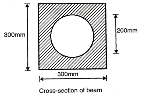
Fig:17
Given shear force S=200kN, a=300mm, d-200mm
To find 
Moment of inertia:

Shear stress at neutral axis
Refer Fig.P.2.24.13(a) 

Shear stress at the top of circle
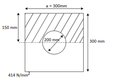
Fig:18


Average shear stress:

Ratio 
The ratio of maxium and average shear stress is 2.66
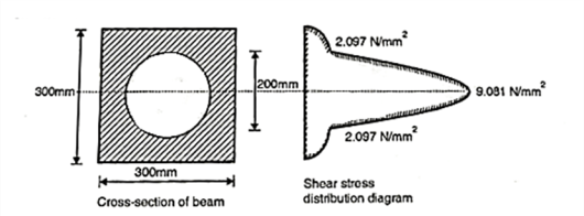
Fig:19
Q. A steel section shown in Fig is subjected to a shear force of 20 k N. Determine shear stresses at important points and sketch shear stress distribution diagram.
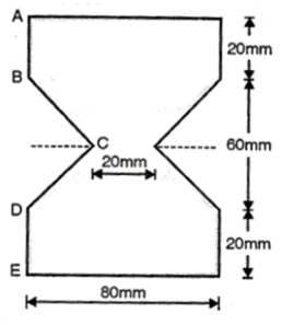
Fig:20
Given S=20kN=10×03N
Position of Neutral axis 
Moment of Inertia

Shear stress At A and E, =0
Shear stress at B

Shear stress at C i.e. neutral axis
 =14.23MPa

Fig:21
Q. The beam section shown in the Fig.is subjected to the shear force of 35 k N. Determine the magnitude of shear stress at important points and plot the same. Also determine average shear stress.
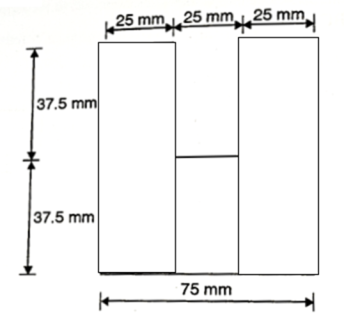
Fig:22
Given: Shear force S=35kN
To find: and max
Position of neutral axis


Moment of Inertia


Shear stress at Neutral axis 
Consider area below N.A.


Shear stress at junction
A= (25×37.5)×2=1875mm2 b1=50mm


Average shear stress


Fig:23
Q. A hollow box section is as shown in Fig., spans a gap of 5 m and is subjected to a u.d.l. Of intensity 3 kN/m including its self weight. Determine the maximum shear stress developed at a section 1.5 m from one end of the section assuming ends simply supported.
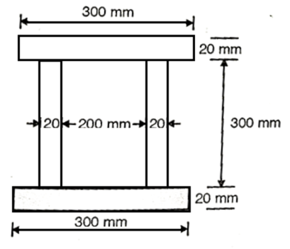
Fig:24
Support reaction:
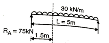
Fig:25


Shear force at 1.5m from support

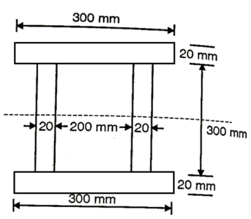
Fig:26
Position of neutral axis

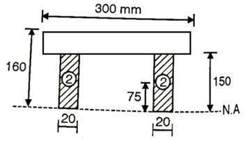
Fig:27
Moment of inertia


Maximum shear stress at neutral axis


Q. An I-beam having the top and bottom flange 120 mm × 20 mm and web of 160 mm×20 mm is subjected to a shear force 100kN. Determine:
i) Maximum and minimum shear stress
Ii) Average shear stress
Iii) % of shear stress carried by web potion
Iv) Draw shear stress diagram.
Given:
S=100kN
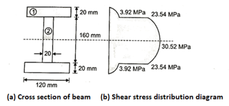
Fig:28
Moment of inertia 

(i) Maximum shear stress occurs at N.A


Minimum shear stress at junction of web and flange


(2)Average shear stress

(iii) % of shear stress carried by web portion

Q. A rectangular beam carries a distributed load of intensity  Beam is simply supported with span length of L meter. Determine the critical length at which shearing stress and bending stress reach their allowable values simultaneously.
Given =
To find Critical length,

For rectangular cross-section

Bending formula

Shearing stress at NA 
Since both shearing stress and bending stress reaches their value simultaneously.

Q. The cross-section of the beam is as shown fig. If this cross-section is subjected to a shear force of 15kN. Draw shear stress distribution diagram and find ratio of maximum shear stress to average shear stress.
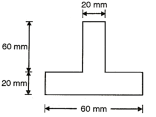
Fig:29
Given shear force s=15kN =
To find 
Position of neutral axis


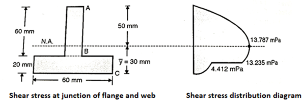
Fig:30
Moment of inertia


Shear stress distribution across the depth
=


Maximum shear stress at neutral axis

Average shear stress

Ratio of  to
to 

References:
- Timoshenko, S. And Young, D. H., “Elements of Strength of Materials”, DVNC, New York USA.
- Kazmi, S. M. A., “Solid Mechanics” TMH, Delhi, India.
- Hibbeler, R. C. Mechanics of Materials. 6th ed. East Rutherford, NJ: Pearson Prentice Hall, 2004
- Crandall, S. H., N. C. Dahl, and T. J. Lardner. An Introduction to the Mechanics of Solids 2nd ed. New York, NY: McGraw Hill, 1979
- Laboratory Manual of Testing Materials - William Kendrick Hall
- Mechanics of Materials - Ferdinand P. Beer, E. Russel Jhonston Jr., John T. DEwolf – TMH 2002.