Unit - 6
Slope and Deflection
The reason of calculating deflection in beam is to decide the vertical intensity of its sag from preliminary horizontal (longitudinal) axis of beam.
The slope is the attitude of beam axis between preliminary function and very last function after deflection.
Deflection of beam controls the powerful duration to intensity ratio of beam.
Consider a simply a supported straight beam subjected to transverse loading. It will deflect about its original axis as shown in fig. The deflected axis of beam is called elastic curve which bends into an arc of a circle with radius of curvature R
The elastic curve is very flat and its slope at any point is very small
Slope tan
As slope is very small
Neglect tan,

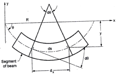
Fig:1
Differentiate w.r.t. x

From fig. 
Where R is radius of curvature for arc length ds

From flexural bending formula


From above equation


Where EI – is the flexural rigidity of the beam
Is above equation is known as differential equation of the elastic curve of a beam.
However, dx/dy is very small is square is still smaller compared to unity
Integrating equation

Slope deflection
(As  )
)
Again integrated w. r. t. x

Deflection equation where c1 and c2 are the constant in integration which can be evaluate by using support boundary equation
Key takeaway:
- The slope is the attitude of beam axis between preliminary function and very last function after deflection.
- Deflection of beam controls the powerful duration to intensity ratio of beam.
- Consider a simply a supported straight beam subjected to transverse loading
The approach in the Slope-deflection slope deflection is to consider each beam element separately and to write down the so-called slope deflection equations for each element, in a somewhat mechanical fashion.
These are mental equations relating the unknown end moments (MM) of any prismatic beam AB to the known fixed-end moments (MM) and the slopes (0,0) and sections (A, A,) at the two ends.
For convenience, the deflections can substitute by chord rotations. Some of these displacements may be equal to zero or May Similar equations are written down for elements BC, CD, in a continuous beam
For convenience, the deflections can but substituted by chord rotations. Some of these displacements may be equal to zero or may own similar equations are written down for elements BC, CD... in a continuous beam.
System or a plane frame system. Then, appropriate equilibrium equations are written down, corresponding to the unknown displacements.
For example, in a continuous beam ABCD the equilibrium equation corresponding to the unknown rotation on is given by MA+ Mac Ma, where Ma is the concentrated moment, if any, applied at B.
These equilibrium equations are then solved simultaneously to yield the unknown displacements.
Substituting the values of the displacements in the slope-deflection equations, we get the desired end moments in each beam element, and thereby the other support reactions. We then have the complete force response.
The method appears to be very simple in concept, but can be challenging while dealing with situations involving unknown deflections (or chord rotations), which are sometimes referred to as sway type problems.
In non-sway type problems, there are only unknown end rotations involved, and these are fairly straight-forward to handle. However, even in such problems, there are several short-cuts possible.
For example, if the extreme end A of a continuous beam ABCD has a hinged support or has an overhang beyond it, we recognize that the end moment MA is statically determinate, and we can avoid treating 0, as an unknown. Similarly, we can handle other boundary conditions such as a guided-fixed support and take advantage of symmetry and anti-symmetry.
However, a word of caution is appropriate here. The slope-deflection method should not be applied blindly, when we seek to take short-cuts.
We need to understand the basic concept underlying the displacement method while applying the modified slope-deflection equations and modified fixed-end moments, wherever appropriate. This makes the analysis exercise interesting and challenging.
1. Analysis of fixes beam by S.D method
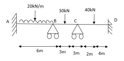
Fig:2
Step 1) Dki = 2 
Step 2) Find Fixed End Moments
Solution:
For AB
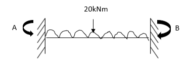
Fig:3


For BC

Fig:4


For CD

Fig:5


Apply S.D. Equation


Joint equilibrium condition


Key takeaway:
- The approach in the Slope-deflection slope deflection is to consider each beam element separately and to write down the so-called slope deflection equations for each element, in a somewhat mechanical fashion.
- The method appears to be very simple in concept, but can be challenging while dealing with situations involving unknown deflections (or chord rotations), which are sometimes referred to as sway type problems.
- In non-sway type problems, there are only unknown end rotations involved, and these are fairly straight-forward to handle.
Moment area method is used to determine the slope and deflection at a point in determinate structure and indeterminate structures.
Theorems of moment are suggested by Mohr’s and thus these theorems are called as Mohr’s theorem there are two theorem which are explained
First theorem:
The angle between the tangent drawn at two-point B and Aon the deflected curve of a beam is equal to the area under the bending moment diagram between two-point A and B divided by EI
Proof:
Consider a beam is shown in fig. Subjected to arbitrary load. The deflected shape and BMD of a beam as shown in fig. Respectively
Consider two points C and D at a elements dx on the beam.
The relation between the radius of curvature and BM for any such section is given by


Where negative sign is used with  since
since  decreases with increases in x from a positive maximum value at x=0 to a negative minimum value at x= L
For whole elastic curve
Diagram:
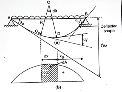
Fig:6
Integrated equation

Where, dA= Area of BMD between point C and D
Change of slope between point B and A
= Area of BMD between B and A / EI
This proves first theorem.
Second Theorem:
Statement:
If A and B are two points on the deflected shape of a beam the vertical distance of point B from the tangent drawn to the elastic curve at point A is equal to moment of area of BMD between point A and B about vertical line from point B divided by EI
Proof:
Consider the distance dy along the vertical line through point B as shown in fig is nearly equal to dt = -XB. d
Integrating equation, we get the vertical distance yBA between the point B and the tangent from point A on the deflected beam

yBA = moment of BMD between A and B at B/ EI
Proved
Numericals:
Q. A cantilever beam is loaded as shown in fig. Using moment area method, find the slope at B and deflection at C. Take EI=5.4×10⁴KN-m2.
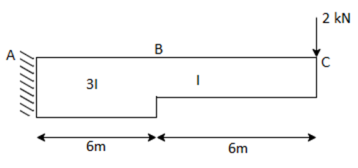
Fig:7
1)Draw deflection shape
2)Draw tangent at B and C.
3)Draw (M/EI) diagram
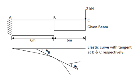
Fig:8
B.M at B=-2×6=-12KN-m
B.M at A=-2×12=24KN-m
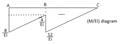
Fig:9
4)Slope at B
 B=area of (M/EI) diagram between A and B
=-
= rad
rad
=6.67×10^-4 rad(clockwise)
5) Deflection at C
Yc=Moment of (M/EI) diagram between A and C about C
=
= =
= m=-8.90×10-3=8.90 mm(
 )
)
Q. A cantilever of length 4 meter, carries U.D.L 12KN/m for a length of 2.5 m from fixed end, determine maximum slope and deflection using moment area method. Take EI=6.3×10⁴KN-m2
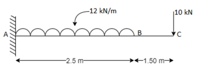
Fig:10
1) Draw beam with loads
2) Draw deflected shape
3) Draw tangent at B.
4) Draw (M/EI) diagram.
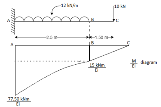
Fig:11
B.M at B=-10×1.5=-15KN-m
B.M at A=-10×4-12×2.5×.5/2=-77.5KN.m
5) Slope at free end C
 c= area of (M/EI) diagram between A and C
=
 c=-
c=- =
=
=1.60×10⁻³rad(sagging)
6) Deflection at free end C
Yc = Moment of (M/EI) diagram about C
=-
=- =
=
= =4.61×10⁻³ m (
 )
)
Yc= 4.61 mm
Q. Using Moment area method, Find the slope and deflection at the free end B of a cantilever beam with uniform cross section, subjected to point load P at the centre of the beam.
1) Draw beam with loads
2) Draw deflected shape
3) Draw tangent at C.
4) Draw (M/EI) diagram.
B.M at C=0
B.M at A =-P× =
=
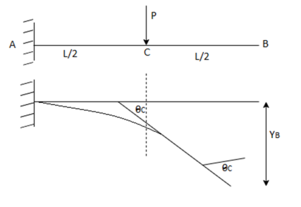
Fig:12

Fig:13
5) Slope at B:
Slope at B=Slope at C=Area of(M/EI) diagram between A and C.
=- =
= (sagging)
6)Deflection at B
YB== Moment of (M/EI) diagram between A and B about B
=- =
=
= (
(
Q. Find slope and deflection for the cantilever AB of span 2m loaded with uniformly distribution load 10KN/m up to 1m from each A by moment area method. Assume uniform flexural rigidity.

Fig:14
1)Draw elastic curve
2)Draw tangent at B
3)Draw M/EI diagram
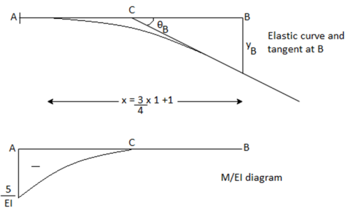
Fig:15
4) Slope at B: Use second theorem,
 Area of (M/EI) diagram between A and B
 =-
=-
5) Deflection at B: Use second theorem,
YB= Moment of (M/EI) diagram between A and B about B
=-
YB=2.92/EI ( )
)
Key takeaway:
- Moment area method is used to determine the slope and deflection at a point in determinate structure and indeterminate structures.
- Theorems of moment are suggested by Mohr’s and thus these theorems are called as Mohr’s theorem there are two theorem which are explained
- The angle between the tangent drawn at two-point B and Aon the deflected curve of a beam is equal to the area under the bending moment diagram between two-point A and B divided by EI
It is a simple method based on the double integration concept in this method bending moment at any section is expressed in the systematically order.
The section x-x is to be taken in the last portion of the beam
In this method bending moment due to each force or udl is separated by a compartment line.
Slope is obtained by integrating bending moment equation and then deflection is obtained by integration of slope equation.
1. Rules of Macaulay’s method
- The section x-x is to be taken in the last portion of the beam
- The quantity in the bracket () should be integrated as a whole
- The expression for BM(Mxx) equation can be used at any point provided the term within the bracket becomes negative is omitted
- Constant of integration C1 and C2 must be written before first vertical line.
2. Step by step procedure:
- Determine the support reaction using available condition of equilibrium.
- Consider the section x-x at a distance x covering all the loads from left end of the beam
- Integrating equation slope equation, we get slope equation
- Again, integrate equation we get, deflection equation.
- The constant of integration C1 and C2 is calculated by applying boundary condition.
- Substitution the value of constant in slope and deflection and write final slope and deflection equation.
- Find slope and deflection at any desired point.
Numericals:
Q. Derive a general expression to find slope and deflection of a simply supported beam of span L subjected to central point load W by Macaulay’s method.
A simply supported beam is subjected to concentrated load W acts at a centre is as shown in fig.
Step 1: Support reaction
∴RA=RB=W/2(
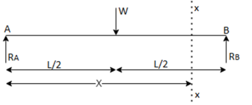
Fig:16
Step 2: Consider a section x-x at a distance x from A as shown in fig.
Moment at section x-x:
Mxx=RA.x-w(x-L/2) = .x-W(x-L/2)
EI =Mxx
=Mxx
EI =
= x-w(x-L/2) …..(1)
Step 3: Integrating Equation1
We get, EI ( )=
)= (
( …..(2)
Step 4: Integrating equation 2
We get, EI(y)= (
( …..(3)
Step 5: Find C1 and C2
Apply boundary condition to find C1 and C2.
When x=0, y=0, put in equation 3 and neglecting last term,
C2=0
When x=L,y=0 put in equation 3 and neglecting last term,
0= (L3) +C1L-
∴C1L=
C1=
Step 6: Write final slope and deflection equation
Put value of C1 and C2 in equation 2 and 3
∴Slope equation,
 ……(4)
……(4)
∴ Deflection equation,
(y)= ……(5)
……(5)
Step 7: Find slope at ends and Deflection under load
(a) Slope at support A
Put x=0 in equation 4, neglecting last term,
∴ =
= (┤)(0-
 )
)
∴ =
= (sagging)
As the beam is symmetrical,
∴ =-
=- B
B
∴ =-
=- (sagging)
(b) Deflection under load
Put x=L/2 in equation 5, neglecting last term,
y = 
= (downwards)
Q. A cast iron beam 50 mm wide and 100 mm deep is simply supported on a span of 1.2m. The beam carries a point load of 15 KN at the centre. Find the deflection at centre. Take E=108000N/mm^2.
Given:
b =50mm
d =100mm
L =1.2 m
E=108000N/mm^2
To find: Deflection at centre Yc,
Moment of Inertia I= =
= =4.16×10^6 mm^4
Flexural rigidity EI=108000×4.16×10^6=4.50×10^11 N-mm2
=450KN-m2
Deflection at centre Yc= =
=
=-1.2×10^-3m
Yc= 1.2mm(downward)
Key takeaway:
- Determine the support reaction using available condition of equilibrium.
- Consider the section x-x at a distance x covering all the loads from left end of the beam
- Integrating equation slope equation, we get slope equation
- Again, integrate equation we get, deflection equation.
- The constant of integration C1 and C2 is calculated by applying boundary condition.
- Substitution the value of constant in slope and deflection and write final slope and deflection equation.
- Find slope and deflection at any desired point.
1. Determinate Beam: the determinate beam is that the beam in which unknown support reactions can be calculated by using static equilibrium equations only.
Example: simply supported beams, cantilever beams, single and double overhanging beams.
Fig:17
2. Slope and Deflection of beams
Macaulay’s method
(Double ∫∫ method)
(Integration)
3. Basics:
1. Elastic curve: Deformed shape of beam is called as elastic curve.
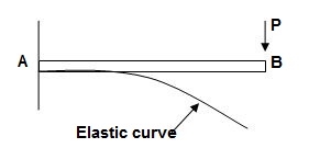
Fig:18
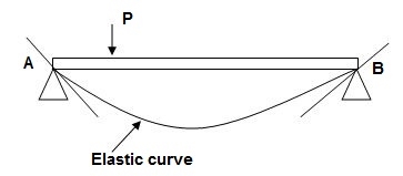
Fig:19
2. Slope: Angle made by tangent joint to the elastic curve with x-axis is called as slope.
3. Deflection: Translation of cross-section normal to the longitudinal axes of member is called as deflection.
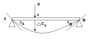
Fig:20
4. Reference System:
Left end of beam is taken as origin and reference system is as below.

Fig:21
5. Sign conventions:
(A). Slope
ϴ + dy/dx = Anticlockwise rotation of tangent
Dy/dx = clockwise rotation of tangent
(B) Deflection
+y = upward Deflection
-y = downward Deflection
6. Flexural Rigidity = (EI)
Product of young modulus of elasticity and moment of inertia of cross-section is called as Flexural rigidity (FI).
Unit: KN.m2
Note: Slope and deflections are inversely proportional to FI.
7. Boundary conditions:
These are nothing but support conditions.
i) At fixed end:

Fig:22
Dy/dx = 0
y = 0
Ii) At hinged and roller end
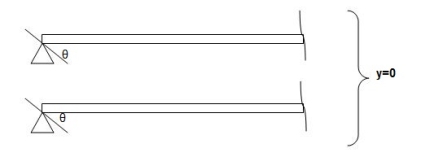
Fig:23
Q. Write boundary conditions for following beams
1)
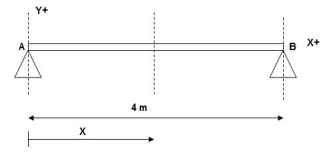
Fig: 6.24
At x = 0; yA = 0
x = 4m; yB = 0
2)
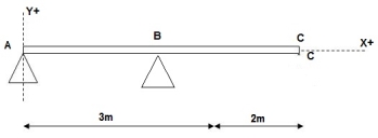
Fig:25
At x = 0; yA = 0
x = 3m; yB = 0
3)
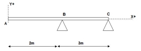
Fig:26
At x = 2m; yB = 0
At x = 5m; yC = 0
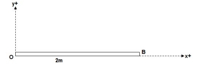
Fig:27
At x = 0; {dy/dx} A = 0
X = 0; yA = 0
8. Concept of Macaulay’s Method
We have,
M/I = 6/y = E/R
Where; R = Radius of curvature
= {1 + (dy/dx)2 }3/2 / d2y/dx2
For beams values of dy/dx are very small
R ≈ 1/d2y/dx2
M/I = E/R, E/1/d2y/dx2 = Ed2y/1 x dx2
M/I = Ex (d2y/dx2)
M = EI.d2y/dx2 = - - - - F(x) = BM eqn
ϴ = EI (dy/dx) = ----------- +c1 = slope eqn
Deflection EI(y) = --------- + C1(x) + C2 = Defneqn
(Eqn of elastic curve)
9. B.M equations:
Note:
For writing BM equation always consider section at a distance x from origin, placed in right extreme zone.
- Case 1
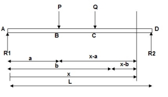
Fig:28
EI (d2y/dx2) = BMx = R1(x) | - P(x-a) | - Q(x-b)
- Case 2
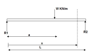
Fig:29
EI (d2y/dx2) = BMx = R1x | - w(x-a)2/2
EI (d2y/dx2) = BMx = R1(x) | - wx2/2 | + w(x-a)2/2
- Case 3:
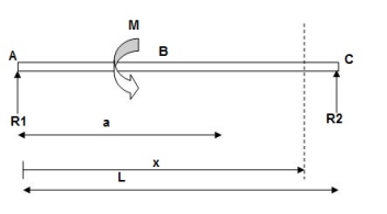
Fig:30
EI(d2y/dx2) = BMx = R1(x) | - M(x-a)
10. Procedure for Macaulay’s method:
i). Find support reactions
Ii). Equations
Iii). Find constants C1& C2 using boundary conditions
Iv). Find slope &deflection
Notes:
1] Value of FI shall be substituted at the end of calculation in KN m2.
2] Answer for slope will be in radians and deflection in meter (m).
3] For simply supported beam at a section where deflection is maximum, slope is zero.
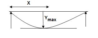
Fig:31
Example:
1) Given:
E = 200 GPa = 200 x 103MPa / N/mm2 = 200 KN/mm2
I = 3 x 108 mm4
EI = 200 x 3 x 108 KNmm2
EI = 600 x 102 KNm2
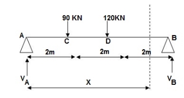
Fig:32
Reactions,
∑MA = VB (6) – 90 x 2 – 120(4) = 0
VB = 660/6
VB = 110 KN
∑Fy = VA + VB – 90 – 120 = 0
VA = -110 +90+120
VA = 100 KN
∑Fx = HA = 0
EI (d2y/dx2) = 100(x) | - 90(x-2) | -120(x-4) ---(1)
EI (dy/dx) = C1 + 100x2/2 | - 90(x-2)2/2 | -120(x-4)2/2 ---(2)
EI(y) = C1(x) + C2 + 100x3/6 | - 90(x-2)3/6 | -120(x-4)3/6 ---(3)
Boundary conditions:
At x=0 | yA = 0, put in (3)
C2 = 0
At x = 6m, yB = 0, put in (3)
6C1 + 100 x 36 – 90 x (4)3/6 – 120 x 23/6 = 0
6C1 + 3600 – 960 – 160 = 0
6C1 = -2480
C1 = (-) 413.33
Slope &Deflection:
X = 0, in (2),
(dy/dx) A = (-) 413.33/EI = (-)4133.33/600 x 102
 = 6.88 x 10⁻³ rad( )
X = 6m in (2),
EI (dy/dx) B = (-)413.33 + 100(6)2/2 – 90(4)2/2 – 120 x (2)2/2
= - 413.33 + 1800 – 720 – 240 = 426.67
 (dy/dx) B = 7.11 x 10⁻³rad( )
X = 2m in (3),
Yc = -413.33 x 2 + 100 x 23/6
= - 826.66 + 133.33
= -693.22/EI = -693.32/600 x 102 = -11.55
 Yc = -11.55 mm( )
X = 4m in (3)
yD = -413.33 x 4 + 100 x 43/6 – 90 x 23/6
= -706.6/EI = -706.6/600 x 102
= - 11.77 mm
 yD = 11.77 mm( )
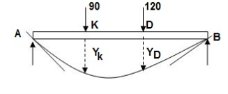
Fig. 33
For maximum deflection
Let X > 2m
< 4m - zone CD
EI (dy/dx) CD = - 413.33 + 100/2x2 – 90(x-2)2/2 = 0
-413.33 + 50 x2 – 45(x-2)2 = 0
-413.33 + 50x2 – 45(x2-4x+4) = 0
-413.33 + 5x2 + 180x – 180 = 0
5x2 + 180x – 593.33 = 0
X = 3.03 >2m
<4m
Assumption is correct
X = 3.03m in (3)
Ymax = -413.33 x 3.03 + 100(3.03)3/6 – 90 x (3.03-2)3/6
= -1252.38 + 463.63 – 16.39
= - 805.14/EI
2) Given:
EI = 4 x 10⁴ Kn.m2
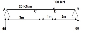
Fig:34
Reactions:
∑MA = 0
VB x 6 – 20 x 3 x 1.5 – 60 x 4 = 0
VB = 55KN
∑Fy = 0
VA + VB – 60 – 20 x 3 = 0
VA = 65 KN
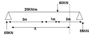
Fig:35
EI (d2y/dx2) = 65 x x | - 20 x x2/2 | + 20 x (x-3)2/2 | - 60(x - -(1)
EI {dy/dx} = C1 + 65x2/2 | - 20 x x3/6 | + 20(x - 3)3/6 | - 60(x - 4)2/2 - - (2)
EI(y) = C1(x) + C2 + 65x3/6 | - 20 x x4/24 | + 20(x-3)4/24 | -60(x-4)3/6 --(3)
Boundary conditions:
At x=0, yA = 0, put in (3)
C2 = 0
X = 6m, yB = 0 put in 3
C1 x 6 + 65 x 62 – 20 x 63/4 + 20 x 34/24 – 60 x 23/6 = 0
C1 = -207.91
Slope &deflection:
X = 3m in (2)
(dy/dx) c = -207.91 + 65 x 32/2 – 20 x 33/6 = -5.41/EI
= -1.35 x 10⁻⁴
 (dy/dx) c = 1.35 x 10⁻⁴ rad( )
X = 3m in 3
yC = -207.9 x (3) + 65 x (3)3/6 – 20 x 34/24 – 398/EI
= - 9.967 x 10-3
= -9.967mm
 yC = 9.967 mm( )
x = 4m in (3)
yD = -207.9 x 4 + 65 x 43/6 – 20 x 43/24 + 20/24
= - 350.7/EI
 = 8.76 mm ( )
3) Given:
EI = 32.5 x 10³ Kn.m2

Fig:36
Reactions:
∑MA = 0
VB (5) – 45 x 3 x 1.5 + 30 = 0
VB = 34.5 KN
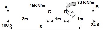
Fig:37
EI {d2y/dx2} = 100.5 x x – 45x2/2 | + 45 x (x-3)2/2 | -30(x-4)0 -- (1)
EI {dy/dx} = C1 + 100.5x2/2 – 45x3/6 | + 45 x (x-3)3/6 | - 30(x-4) --(2)
EI(y) = C1(x) + C2 + 100.5x3/6 – 45x4/24 | + 45 x (x-3)4/24 | - 3(x-4)2/2 --(3)
Boundary conditions:
At x=0; yA = 0 put in eqn3
C2 = 0
At x=5; yB = 0
5C1 + 100.5 x 53/6 – 45(5)4/24 + 45(2)4/24 – 30/2 = 0
C1 = (-) 187.375
Slope &Deflection:
X=3m in (2)
(dy/dx) c = -187.375 + 100.5 x 32/2 – 45(3)3/6
= 62.375/32.5 x 103
 (dy/dx) c = 1.919 rad( )
X = 3m in (3)
yC = -187.375 x 3 + 100.5 x 33/6 – 45 x 34/24
= - 261.75/32.5 x 103
= - 8.053mm
 yC = 8.053mm( )
x = 4m in (3)
yD = -187.375 x 4 + 100.5 x (4)3/6 – 45 x (4)4/24 + 45/24
= - 155.625/32.5 x 103
= - 4.78 mm
 yD = 4.78 mm( )
Q. Find deflection of given beam?
Given:
E = 200 GPa
I = 6.2 x 107mm4
EI = 200 x 6.2 x 107 KN.mm2
= 200 x 6.2 x 107 x 10-6 KNm2
EI = 12400 KNm2
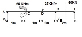
Fig:38
Reactions:
∑MA = 0
VB x 4 – 25 – 37(2)(3) – 60(6) = 0
VB = 151.75 KN
VA + VB – 60 – 37 x 2 = 0
VA = (-)217.75 KN
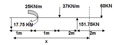
Fig:39
EI {d2y/dx2} = -17.75 x | + 25(x-1)0 | - 37 x (x-2)2/2 | + 151.75(x-4)2/2 | + 37 x (x-4)2/2 --(1)
EI {dy/dx} = C1 – 17.75x2/2 | + 25(x-1) | - 37(x-2)3/6 | + 151.75(x-4)2/2 | + 37(x-4)3/6 --- (2)
EI(y) = C1x + C2 – 17.75 x3/6 | +25(x-1)2/2 | -37(x-2)4/24 | + 151.75(x-4)3 | + 37(x-4)4/24 ---(3)
Boundary condition:
At x=0; yA=0 C2 = 0 (in eqn (3))
At x=4; yB=0 put in eqn (3)
4C1 – 17.75 x 43/6 + 25 x 32/2 – 37 x 23/6 = 0
C1 = 25.4
Slope and deflection:
X = 2m in (2) & (3)
(dy/dx) D = 25.4 –17.75 x 2 + 25
= 14.9/EI
 (dy/dx) D = 1.201 x 10⁻³rad( )
yD = 25.4 x 2 – 17.75 x 23/2 + 25/2
= 39.63/12400
 yD = 3.196 mm( )
x = 6m in (2) & (3),
(dy/dx) E = 25.4 – 17.75 x 62/2 + 25 x 5 – 37(4)3/6 + 151.75(2)2/2 + 37 x 23/6
= -210.183/12400
 = 0.017 rad( )
YE = - 341.7/12400 = 27.5mm
Key takeaway:
- Find support reactions
- Equations
- Find constants C1& C2 using boundary conditions
- Find slope &deflection
References:
- Timoshenko, S. And Young, D. H., “Elements of Strength of Materials”, DVNC, New York USA.
- Kazmi, S. M. A., “Solid Mechanics” TMH, Delhi, India.
- Hibbeler, R. C. Mechanics of Materials. 6th ed. East Rutherford, NJ: Pearson Prentice Hall, 2004
- Crandall, S. H., N. C. Dahl, and T. J. Lardner. An Introduction to the Mechanics of Solids 2nd ed. New York, NY: McGraw Hill, 1979
- Laboratory Manual of Testing Materials - William Kendrick Hall
- Mechanics of Materials - Ferdinand P. Beer, E. Russel Jhonston Jr., John T. DEwolf – TMH 2002.