Unit-5
Structural behavior of footings
The shear resistance of column columns and base slides varies greatly at different levels. The reason for this is because the standards differently define the position of the critical perimeter where the resistance of the fist must be determined, and measure the influence of key parameters such as active depth, sleep shear, concrete compression strength, longitudinal stiffness and stiffness give reinforcement pressure in various ways.
To measure the level of safety in Eurocode 2 and fib MC 2010, their construction results are compared with the results of a series of foot tests tested in real-world boundary conditions. In addition to the results of the experiments conducted, an analysis of other boxing investigations that lay on the real ground was included.
Thus found the answer to the question of how the individual characteristics of the layers and the soil affect the resistance of the fists and how Eurocode 2 and fib MC 2010 predict the carrying capacity of the tested column columns.
Finally, based on the results of testing and testing of others, and the continuation of price analysis, a possible transformation of Eurocode 2 in the field of reinforced concrete was proposed.
Introduction
Shallow foundations move structural loads to nearby soil. Foot columns and foundation stone foundations are the main types of shallow foundations and building members that support columns. The control of the column of such steps is a mandatory part of the construction of reinforced concrete tires exposed to the designated strengths of the columns.
The complexity of the compression situation in the paralyzed feet requires, as well as a detailed analysis of theories, further exploratory research to determine the appropriate conclusions and to confirm the theoretical presentations presented.
The behavior of the foot columns and slide foundations under load depends on the general condition of the soil characteristics, the type and the characteristics of the tread material and the strength of the load. Often, high-load-mounted loads can lead to a sudden failure of those steps - hitting the column with the foot.
Although foundations have a significant impact on structural and soil behavior, standards are not sufficiently sensitive to their analysis, and in some cases specific foundation analysis data have not even been mentioned.
The following are the steps as how the footing design is being proceeded-
1. Proportion of footing for column
2. Check for bending moment
3. Check for one-way shear
4. Check for two-way shear
5. Check for bearing stress
6. Check for development length
Design steps
Step 1: Transfer of axial force at the base of column
It is essential that the total factored load must be transferred at the base of columns without any reinforcement .For that the bearing resistance should be greater than the total factored load up
Pu = 1.5 × P
The bearing stress as per cl 34.4 of IS 456
 b r = 0.45 f ck ( A1/A2)1/2
With a condition that
(A1/A2)1/2 <= 2.0
Step 2: Size of the footing
Base area = P × 1.15 / 300
Provide B× D mm .........assume A/2
Step 3: Thickness of footing
Tan  <= 0.9 {(100 QA/f c k)+1}1/2
Therefore h = {(D - P)/2} (tan )
)
Provide B×D×h mm
Step 4: Minimum reinforcement
The plain concrete block B×D×h shall be provided with the minimum reinforcement 0.12 per cent for temperature, shrinkage and tie action
Minimum A s t = 0.0012 Bh
Step 5: Check for the gross base pressure
Assuming unit weight of concrete and soil as 24 KN/m3 and 20 kN/me
Service Load = P kn
Weight of footing = (0.67)(1.25)(1.25)(24)
Weight of soil = (0.33)(1.25)(1.25)(20)
Total = weight of footing + weight of soil + service load
Q a = total /(1.25)(1.25)
Step 6: bending moment
Step 7: development length of 12 mm diameter bars
Step 8: providing slope in the footing slabs
Numerical
Problem 1
Design a plain concrete footing for a column of 400 mm x 400 mm carrying an axial load of 400 kN under service loads. Assume safe bearing capacity of soil as 300 kN/m at a depth of 1 m below the ground level. Use M 20 and Fe 415 for the design.
Solution 1:
Plain concrete footing is given in section .11.28.2(A)1 and 11.28.5(b).
Step 1: Transfer of axial force at the base of column
It is essential that the total factored loads must be transferred at the base of column without any reinforcement. For that the bearing resistance should be greater than the total factored load P
Here, the factored load P. = 400(1.5) = 600 kN.
The bearing stress, as per cl.34.4 of IS 456
 = 0.45 f c k (A1/A2)1/2
With a condition that
(A1/A2)1/2 < 2.0
Since the bearing stress at the column-footing interface will be governed by the column face, we have A1 = A2 = 400(400) = 160000 mm2 Using A1 = A2 in Eq.
P b r = Bearing force = 0.45 f c k A1 = 0.45(20)(160000)(10^-3) = 1440 k N > P u (= 600 kN).
Thus, the full transfer of load P is possible without any reinforcement.
Step 2: Size of the footing
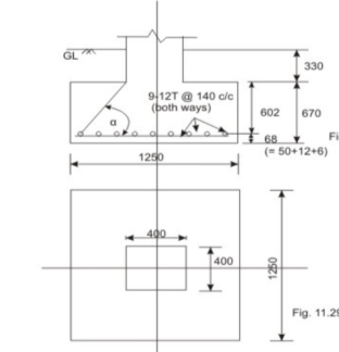
Fig no 1 Detailing
Let us assume the weight of footing and back fill soil as 15 per cent of P Then, the base area required = 400(1.15)/300 = 1.533 m2. Provide 1250 x 1250 mm (= 1.5625 m2) as shown in Fig. The bearing pressure q a = 400(1.15) / (1.25)(1.25) = 294.4 k N/m2.
Step 3: Thickness of footing
The thickness of the footing h is governed by Lesson 28. From below given by
Tan  <= 0.9 {(100 q a / f c k) + 1}1/2
Tan  <= 0.9 [{100(0.2944)/20} + 1]1/2
Tan  <= 1.415
We have
h = ((1250 - 400)/2)(tan ) = 601.375 mm
Provide 1250 x 1250 x 670 mm block of plain concrete.
Step 4: Minimum reinforcement
The plain concrete block 1250 x 1250 x 670 shall be provided with the minimum reinforcement 0.12 percent for temperature, shrinkage and tie action.
Minimum A = 0.0012(1250)(670) = 1005.0 mm2
Provide 9 bars of 12 mm diameter (= 1018 mm2) both .The spacing of bars = (1250 - 50 - 12)/8 = 148.5 mm c/c. Provide the bars @ 140 mm c/c.
Step 5: Check for the gross base pressure
Assuming unit weights of concrete and soil as 24 kN/m and 20 kN/m
Service load = 400.00 kN
Weight of footing = (0.67)(1.25) (1.25) (24) = 25.125 KN
Weight of soil = (0.33)(1.25)(1.25)(20) = 10.3125 kN
Total = 435.4375 kN
Q a = 435.4375/(1.25)(1.25) = 278.68 kN/m² < 300 kN/m2
Problem 2:
Design an isolated footing for a square column, 400 mm x 400 mm with 12-20 mm diameter longitudinal bars carrying service loads of 1500 kN with M 20 and Fe 415. The safe bearing capacity of soil is 250 kN/m² at a depth of 1 m below the ground level. Use M 20 and Fe 415.
Solution
Step 1: size of the footing
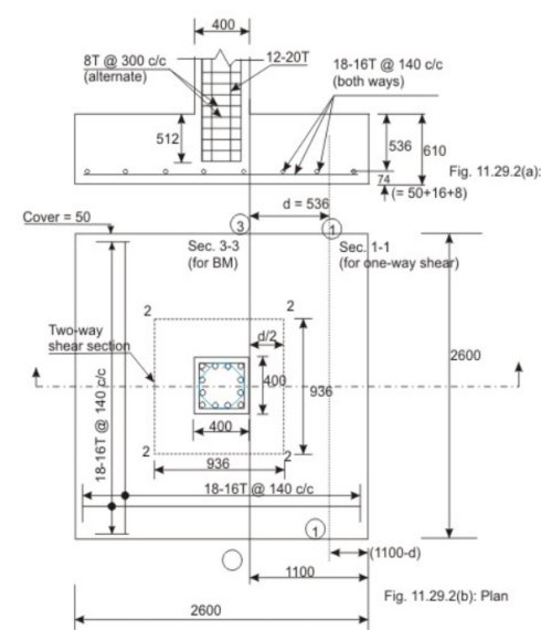
Fig no 2 Detailing
Given P = 1500 kN, g = 250 kN/m at a depth of 1 m below the ground level. Assuming the weight of the footing and backfill as 10 per cent of the load, the base area required = 1500(1.1)/250 = 6.6 m. Provide 2.6 m x 2.6 m, area = 6.76 m
Step 2: Thickness of footing slab based on one-way shear
Factored sol pressure = 1500(1.5)/(2.6)2.6) = 0.3328 N/mm, say, 0.333 N/mm2
Assuming p= 0.25% in the footing slab, tor M 20 concrete, Tc= 0.36 N/mm (Table 19 of IS 456). Vu - 0.36(2600)d and V u(actual) = 0.333(2600)(1100-d). From the condition that should be more than or equal to the actual V we have
0.36(2600)d >= 0.333(2600) (1100-d)
So, d >= 528.57 mm.
Provide d = 536 mm. The total depth becomes 536 + 50 + 16 + 8 (with 50 mm cover and diameter of reinforcing bars = 16 mm) = 610 mm.
Step 3: Checking for two-way shear
The critical section is at a distance of d/2 from the periphery of the column The factored shear force (Fig. 11.29.2b, sec. 2222) = 0.333{(2600)2 - (400 + d)2}(10^-3) = 1959.34 kN. Shear resistance is calculated with the shear strength = ks Tc = ks (0.25) (f c k)^1/2 where k s = 0.5 + B c (cl. 31.6.3 of IS 456). Here B c= 1.0, ks = 1.5 > 1; so ks = 1.0. This gives shear strength of concrete = 0.25 (f c k)^1/2 = 1.118 N/mm2. So, the shear resistance (1.118) 4 (936)(536)= 2243.58 kN > 1959.34 kN. Hence, ok.
Thus, the depth of the footing is governed by one-way shear.
Step 4: Gross bearing capacity
Assuming unit weights of concrete and soil as 24 kN/m and 20 k N/mm respectively:
Given the service load = 1500 kN
Weight of the footing = 2.6(2.6)(0.61)(24) = 98.967 N
Weight of soil = 2.6(2.6)(1.0-0.61)(20) = 52.728 kN (Assuming depth of the footing as 1.0 m)
Total = 1635.2 KN
Gross bearing pressure = 1635.2/(2.6)(2.6) = 241.893 k N/m2 < 250 k N/m2 .Hence, ok.
Step 5: Bending moment
The critical section (Fig.11.29.2b, sec.3.3), is at the face of the column.
Mu = 0.333(2600)(1100)(550) Nmm = 523 809 kNm
Moment of resistance of the footing = Rbd2 where R= 2.76
Moment of resistance = 2.76(2600)(536)(536) = 2061.636 kNm > 523.809 kNm.
Area of steel shall be determined which is
Mu = 0.87 ft A s t d {1 - (A s t ft /f c k BD)}
Substituting Mu = 523.809 k Nm, f y = 415 N/mm2, f c k = 20 N/mm2, d= 536 mm,b = 2600 mm, we have:
Solving, we get Au = 2825.5805 mm2
Alternatively, we can use Table 2 of SP-16 to get the Au as explained below:
Mu/bd2 = 523.809(10^6)/(2600)(536)(536) = 0.7013 N/mm2. Table 2 of SP-16 gives p = 0.2034.
A s t = 0.2034(2600)(536)/100 = 2834.58 mm2
This area is close to the other value = 2825.5805 mm2
However, one-way shear has been checked assuming p= 0.25%. So, use p= 0.2. A s t =0.0025(2600)(536) = 3484 mm2.
Provide 18 bars of 16 mm diameter (= 3619 mm2) both ways. The spacing of bars = {2600 - 2(50) - 16}/17 = 146.117 mm. The spacing is 140 mm c/c
The bending moment in the other direction is also the same as it is a square footing. The effective depth, however, is 16 mm more than 536 mm. But, the area of steel is not needed to be determined with d = 552 mm as we are providing 0.25 per cent reinforcement based on one-way shear checking
Step 6: Development length
Ld = f s  /4 (
/4 ( ) = 0.87(415)(16)/4(1.6)(1.2) = 47(16) = 752 mm (cl.26.2.1 of IS 456)
Length available = 1100 - 50 = 1050 mm > 752 mm.
Step 7: Transfer of force at the base of the column
P = 1500(1.5) = 2250 kN
Compressive bearing resistance = 0.45 f c k (A1/A2)1/2. For the column face A1/A2 = 1 and for the other face A1/A2 > 2 but should be taken as 2. In any case, the column face governs
Force transferred to the base through column at the interface = 0.45(20)(400)(400) = 1440 kN < 2250 kN. The balance force 2250 - 1440 = 810 kN has to be transferred by the longitudinal reinforcements, dowels or mechanical connectors. As it is convenient, we propose to continue the longitudinal bars (12-20 mm diameter) into the footing.
The required development length of 12-20 mm diameter bars, assuming a stress level of 0.871 fy (810/2250) = 129.978 N/mm2, is 129.978(20)/4(1.6)(1.2) (1.25) = 270.8 mm. Here  b d for M 20 = 1.2 N/mm2, increased factor of 1.6 is due to deformed bars and increased factor of 1.25 is for the compression
Length available = 610 - 50 - 16 - 16 - 16 = 512 mm > 270.8 mm .Hence, ok. The arrangement is shown in below fig
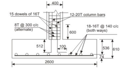
Fig no 3 Detailing
For the balance force 810 kN, the area of dowels = 810000/0.67(415) = 2913.15 mm2. Minimum area=0.5(400)(400)/100 = 800 mm2 < 2913.15 mm2 (cl.34.4.3 of IS 456). Therefore, number of 16 mm dowels = 2913. 15/201 = 15. The development length of 16 mm dowels in compression = 0.87(415) (16)/4(1.6)(1.2)(1.25) = 601.76 mm. Available vertical embedment length = 610 - 50 - 16 - 16 - 16 = 512 mm. So, the dowels will be extended by another 100 mm horizontally, as shown in fig
Problem 3:
Design a sloped footing for a square column of 400 mm x 400 mm with 16 longitudinal bars of 16 mm diameter carrying a service load of 1400 KN. Use M 20 and Fe 415 both for column and footing slab. The safe bearing capacity of soil is 150 kN/m,
Solution 3
Step 1: Size of footing
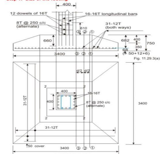
Fig no 4 Detailing
Given P = 1400 KN and q c = 150 KN/m2. Assuming the weight of the footing and the back file as 10 per cent of the load the required base area is: 1400(1.1)/150 = 10.27 m2. Provide 3400 x 3400 mm giving 11.56 m2
Step 2: Thickness of footing slab based on one-way shear
Factored bearing pressure = 1400(1.5)/(3.4)(3.4) = 181.66 k N/m2 = 0.18166 N/mm2. Assuming 0.15 per cent reinforcement in the footing slab Table 19 of IS 456 gives for M 20 = 0.28 N/mm2. From the condition that the one way shear resistance >= one-way shear force, we have at a distance from the face of the column
0.28(3400)d >= 0.18166(1500 - d)(3400)
Or d >= 590.24 mm.
Provide total depth of footing as 670 mm, so that the effective depth = 670 - 50 -16 - 8 = 596 mm. (The total depth is, however, increased to 750 mm in Step 7)
Step 3: Checking for two-way shear
At the critical section 2222 the shear resistance = 4(400 + 596) (596) (0.25)(f c k)^1/2 = 2654.73 KN.
The Shear force {(3.4)(3.4) - (0.996)(0.996))0.18166 = 1919.78 KN < 2654.73 k N. Hence
Step 4: Gross bearing capacity
Assuming unit weights of concrete and soil as 25 kN/m3 and 18 k N/m3respectively, we have:
Load on footing = 1400.00 kN
Weight of footing = (3.4)(3.4)(0.67)(25) = 193.63 kN
Weight of soil = (3.4)(3.4)(1.25 - 0.67)(18) = 120.69 KN (Assuming the depth of the footing as 1.25 m).
Total = 1714.32 KN
Gross bearing capacity = 1714.32 / (3.4)(3.4) = 148.30 k N/m < 150 k N/m2 . Hence ok
Step 5: Bending moment
We have to determine the area of steel in one direction as it is a square footing. So, we consider the lower effective depth which is 596 mm. The critical section is sec.33 where we have
Mu = 3400(1500)(0.18166)(1500)/2 = 694.8495 kNm
Mu /bd2 = 694.8495(10^6)/(3400)(596)(596) = 0.575 N/mm2
Table 2 of SP-16 gives, p = 0.165%. Accordingly, area of steel = 0.165(3400)(596)/100 = 3343.56 mm2 .Provide 30 bars of 12 mm diameter (= 3393 mm2), both ways.
Step 6: Development length
Development length of 12 mm diameter bars - 0.87(415)(12)/4(1.6)(1.2) = 564.14 mm, Hence, ok
Step 7: Providing slope in the footing slab
Since the three critical sections (I e, of bending moment, two-way shear and one-way shear) are within a distance of 596 mm from the face of the column the full depth of the footing slab is provided up to a distance of 700 mm from the face of the column. However, by providing slope the available section now is a truncated rectangle giving some less area for the one-way shear.
Accordingly the depth of the footing is increased from 670 mm to 750 mm. With a cover of 50 mm and bar diameter of 12 mm in both directions, the revised effective depth = 750 - 50 - 12 - 6 = 682 mm. Providing the minimum depth of 350 mm at the edge, as shown in Figs. 11.29.3a and b, we check the one-way shear again taking into account of the truncated rectangular cross-section at a distance of 682 mm from the face of the column.
One-way shear force = 0.18166(1500 - 682)(3400) = 505232.792 N
Area of truncated rectangle = 1800(682) + 1600(282) + 1600(682-282)/2
=1998800 mm
The shear stress = 505232.792/1998800 = 0.2527 N/mm2 < 0.28 N/mm2.
Hence ok.
Step 8: Revised area of steel
The bending moment in step 5 is 694 8495 kNm at the face of the column. With d= 682 mm now, we have
Mu/bd2 = 694.8495(10^6)/(3400)(682)(682) = 0.4394 N/mm2
Table 2 of SP-16 gives p is less than 0.15 percent. Provide p=0.15 percent due to the one-way shear. So A s t= 0.15(3400)(682)100 = 3478.2 mm2. Provide 31 bars of 12 mm (A s t = 3506 mm2), both ways. Effectively, the number bars has increased from 30 to 31 now
Step 9: Transfer of force at the base of the column
P u = 1400(1.5) = 2100 kN. Compressive bearing resistance = 0.45
F c k (A1/A2)1/2 = 0.45(20)(1) = 9 N/mm2.
Force transferred at the base through the column = 9(400)(400)(10^-3) = 1440 kN < 2100 kN.
Provide dowels for the excess (2100 - 1440) - 660 KN. The area of dowels = 660(10^3)/(0.67)(415) = 2373.67 mm2. Minimum area of dowels = 0.5(400)(400) /100 = 800 mm2. Provide 12 dowels of 16 mm diameter (area 2412 =mm2)
The development length of 16 mm dowels = 0.87(415)(16) /4(1.6)(1.2)(1.25) = 601.76 mm.
The vertical length available 750 - 50 - 12 - 12 - 16 = 660 mm > 601.76 mm. Hence, ok.
Key takeaways:
Design steps
1. Proportion of footing for column
2. Check for bending moment
3. Check for one-way shear
4. Check for two-way shear
5. Check for bearing stress
6. Check for development length
Whenever two or more columns in a straight line are carried with one foot spread, it is called a composite foot. The separated feet of each column are usually economical.
Combined feet are provided only when they are most needed, as
1. When two columns are close together, they form a series of adjacent layers
2. When the carrying capacity of the soil is low which causes the formation of adjacent independent feet.
3. Proximity to the building line or existing building or sewage, adjacent to the building column.
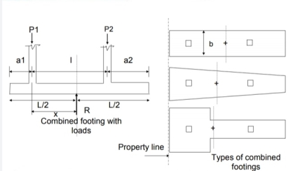
Fig no 5 Combined footing
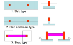
Fig no 6 Type of footing
The jointed foot can be rectangular, trapezoidal or shaped like a Tee in order.
The geometric size and configuration are set in such a way that of the foot area corresponds to the effect of the column loads. This leads to the same pressure under the entire foot area.
Trapezoidal foot is provided when one column load is significantly higher than the other. As a result, both movement rates over the surface of the columns will be limited.
A rectangular foot is provided where any treadmill is restricted or the width of the foot is restricted.
Rectangular combined footing
Over time, the foot acts as a loaded beam that falls between the columns and the upper cantilevering. Statistics, shaving power and temporary bending curves are used in the long-distance direction. The time is checked on the face of the column. Shear strength is most important in the d range in the surface of the columns or where the resistance is reversed. Two-shear shear is tested under a heavy column.
The foot also has a flexible curve and this bend spreads over a short clip near the foot

Fig no 7 Slab type combined footing
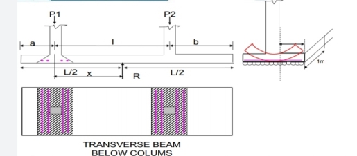
Fig no 8 Transverse beam
Design Steps
Find the point of use of column loads on foot.
Align the foot so that the effect of the load passes through the center of the foot,
Calculate the area of the foot so that the soil is allowed the pressure does not exceed
Calculate shear strength and bending times in important points therefore draw SFD and BMD.
Adjust the depth of the feet from the upper bend a moment.
Calculate the passing moment of the pass and arrange the shortcut section in depth and reinforcement. See anchorage and shear.
Design Steps
Look at the base of the longitudinal shear so form a longitudinal shear
Create minute-length reinforcement and place them in the right places.
Check the length of the development of the long metal
Reduce long-term economic barriers • Draw and provide reinforcement information
Adjust the bar bending system
Detailing
The metal details (both length and length) on the jointed feet are similar to those of the standard SP-34 beam
The required details of the beams and slabs should be followed as appropriate-SP-34
NUMERICAL
Design of combined footing - Slab and Beam type
1. Two interior columns A and B carry 700 kN and 1000 kN loads respectively. Column A is 350 mm x 350 mm and column B is 400 mm X 400 mm in section. The centre to centre spacing between columns is 4.6 m. The soil on which the footing rests is capable of providing resistance of 130 kN/m2. Design a combined footing by providing a central beam joining the two columns. Use concrete grade M25 and mild steel reinforcement.
Draw to a suitable scale the following
1. The longitudinal sectional elevation
2. Transverse section at the left face of the heavier column
3. Plan of the footing
Solution:
Data
F c k = 25 N/mm2
F y = 250 N/mm2
F b = 130 kN/m2 (SBC),
Column A = 350 mm x 350 mm,
Column B = 400 mm x 400 mm,
C /c spacing of columns = 4.6 m,
PA = 700 kN and PB = 1000 kN
Required: To design combined footing with central beam joining the two columns.
Ultimate loads
P A= 1.5 x 700 = 1050 k N, P B = 1.5 x 1000 = 1500 kN
Proportioning of base size
Working load carried by column A = PA = 700 kN
Working load carried by column B = PB = 1000 kN
Self weight of footing 10 % x (PA + PB) = 170 kN
Total working load = 1870 kN
Required area of footing = Af = total load/SBC
=1870/130 = 14.38 m2
Let the width of the footing = Bf = 2m
For uniform pressure distribution the C.G. Of the footing should coincide with the C.G. Of column loads. Let x be the distance of C.G. From the centre line of column A
Then x = (PB x 4.6)/(PA + PB) = (1000 x 4.6)/(1000 +700)= 2.7 m from column A.
If the cantilever projection of footing beyond column A is 'a' then, a + 2.7 = Lf /2 = 7.2/2, Therefore a = 0.9 m
Similarly if the cantilever projection of footing beyond B is 'b' then, b + (4.6-2.7) = Lf /2= 3.6 m,
Therefore b = 3.6 - 1.9 = 1.7 m
The details are shown in Figure

Fig no 9 Combined footing with loads
Rectangular Footing with Central Beam:
Design of Bottom slab
Total ultimate load from columns = Pu = 1.5(700 + 1000) = 2550 kN.
Upward intensity of soil pressure Wu = P/A f= 2550/14.4 =177 kN/m2
Design of slab
Intensity of Upward pressure = wu =177 kN/m2
Consider one meter width of the slab (b=1m)
Load per m run of slab at ultimate = 177 x 1 = 177 kN/m
Cantilever projection of the slab (For smaller column)
=1000 - 350/2 = 825 mm
Maximum ultimate moment = 177 x 0.8252/2 = 60.2 kN-m.

Fig no 10
For M25 and Fe 250, Q u max = 3.71 N/mm2
Required effective depth = √ (60.2 x 10^6 /(3.71 x 1000)) = 128 mm
Since the slab is in contact with the soil clear cover of 50 mm is assumed.
Using 20 mm diameter bars
Required total depth = 128 + 20/2 + 50 =188 mm say 200 mm Provided effective depth = d =200-50-20/2 = 140 mm
To find steel
Mu/bd2 =3.07<3.73, URS
Mu =0.87 f y A s t [d-f y A s t /(f c k b)]
Pt =1.7%
A s t = 2380 mm2
Use  20 mm diameter bar at spacing = 1000 x 314 / 2380 = 131.93 say 130 mm c/c
Area provided = 1000 x 314 / 130 = 2415 mm2
Check the depth for one-way shear considerations- At d from face
Design shear force= Vu =177x(0.825-0.140)= 121KN
Nominal shear stress=  =Vu /bd=121000/(1000x140)=0.866MPa
Permissible shear stress
Pt = 100 x 2415 / (1000 x 140) = 1.7 %,
 u c= 0.772 N/mm2
Value of k for 200 mm thick slab = 1.2
Permissible shear stress = 1.2 x 0.772 = 0.926 N/mm2 > and hence safe
The depth may be reduced uniformly to 150 mm at the
Check for development length
L d t = [0.87 x 250 / (4 x 1.4)]  =39
=39 
= 39 x 20 = 780 mm
Available length of bar=825 - 25 =800mm > 780 mm and hence safe.
Transverse reinforcement
Required A s t =0.15bD/100
=0.15x1000 x 200/100 = 300mm2
Using  8 mm bars, Spacing=1000x50/300 = 160 mm
Provide distribution steel of  8 mm at 160 mm c/c. <300, <5d
Design of Longitudinal Beam
Load from the slab will be transferred to the beam. As the width of the footing is 2 m, the net upward soil pressure per meter length of the beam = Wu = 177 x 2 = 354 kN/m
Shear Force and Bending Moment
V a c= 354 x 0.9 =318.6 kN, VAB = 1050-318.6 =731.4 kN
V B d = 354 x 1.7 = 601.8kN, VBA = 1500-601.8 = 898.2 kN
Point of zero shears from left end C
X1 = 1050/354 = 2.97m from C or
X2 = 7.2-2.97 = 4.23 m from D
Maximum B.M. Occurs at a distance of 4.23 m from D, MuE = 354 x 4.23^2/2 - 1500 (4.23 - 1.7) = -628 kN.m
Bending moment under column A= M u A =354x0.9^2 /2 = 143.37 kN.m
Bending moment under column B = MuB = 354 x 1.7^2 = 511.5 kN-m
Let the point of contra flexure be at a distance x from the centre of column A
Then, Mx = 1050x - 354 (x + 0.9)^2/2 = 0
Therefore x = 0.206 m and 3.92 m from column A i.e. 0.68 m from B.
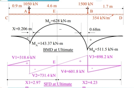
Fig no 11 SFD and BMD
Depth of beam from B.M.
The width of beam is kept equal to the maximum width of the column i.e. 400 mm. Determine the depth of the beam where T- beam action is not available. The beam acts as a rectangular section in the cantilever portion, where the maximum positive moment = 511.5 kN/m.
d =√ (511.5 x 10^6 /(3.73 x 400)) = 586 mm
Provide total depth of 750 mm. Assuming two rows of bars with effective cover of 70 mm.
Effective depth provided = d= 750-70 = 680 mm (Less than 750mm and hence no side face steel is needed.
Check the depth for Two-way Shear
The heaver column B can punch through the footing only if it shears against the depth of the beam along its two opposite edges, and along the depth of the slab on the remaining two edges. The critical section for two-way shear is taken at distance d/2 (i.e. 680/2 mm) from the face of the column. Therefore, the critical section will be taken at a distance half the effective depth of the slab (ds/2) on the other side as shown in Fig.
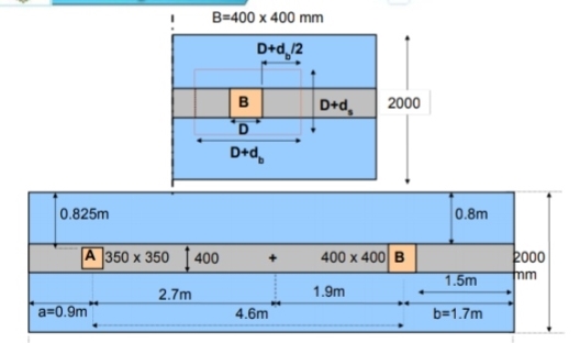
Fig no 12 Detailing
In this case b=D=400 mm, db =680 mm, ds = 140 mm
Area resisting two - way shear = 2(b x db + ds x d s)+2 (D + d b)ds
= 2 (400 x 680+ 140 x 140) + 2(400+680) 140= 885600 mm2
Design shear =Pu d = column load - Wu x area at critical section
= 1500 - 177 x(b + d s) x (D + db)
= 1500-177 x (0.400+0.140) x (0.400+ 0.680) =1377.65KN
T v =P is/ bo d= 1377.65x1000/885600= 1.56 MPa
Shear stress resisted by concrete = T u c = T u c × Ks
Where,  u c= 0.25 √fck = 0.25 √25 = 1.25 N/mm²
Ks = 0.5 + d/D = 0.5 + 400/400 = 1.5 <1 Hence K s= 1
 u c= 1 x 1.25 = 1.25 N/mm2 Therefore Unsafe
Area of Steel: Cantilever portion BD
Length of cantilever from the face of column
=1.7- 0.4/2 = 1.5 m.
Ultimate moment at the face of column =354x1.5^2/2 =398.25 kN-m
Mu max = 3.71 x 400 x 680^2 x 10^ -6 = 686 kN-m > 398.25 kN-m
Therefore Section is singly reinforced.
Mu/bd^2 =398.25x10^6 /(400x680^2) = 2.15<3.73, URS
Pt =1.114%
A s t =3030 mm2, Provide 3-  32 mm + 4-
  16 mm at bottom face,
Area provided = 3217 mm2
L d t = 39 x 32 = 1248 mm
Curtailment
All bottom bars will be continued up to the end of cantilever. The bottom bars of 3-  32 will be curtailed at a distance d (= 680 mm) from the point of contra flexure (a = 680 mm) in the portion BE with its distance from the centre of support equal to 1360 mm from B.
Cantilever portion AC
Length of cantilever from the face of column =900-350/2 = 725 mm
Ultimate moment 354 x 0.7252 /2 = 93 kN-m
Mu /bd2 =93x10^6/(400x6802) =0.52 <3.73, URS
Pt =0.245% (Greater than minimum steel)
A s t =660 mm2
Provide 4 -  16 mm at bottom face, Area provided 804 mm2 Continue all 4 bars of 16 mm diameter throughout at bottom.
Region AB between points of contra flexures
The beam acts as an isolated T-beam.
b = [Lo/ ( Lo/b +4)] + b w where,
Lo = 4.6 - 0.206 - 0.68 = 3.714 m = 3714 mm
b= actual width of flange = 2000 mm, bw = 400 mm
Bf = [3714/(3714/2000+4) + 400] =1034mm < 2000mm
Df =200 mm, Mu = 628 kN-m
Moment of resistance M u fof a beam for xu = D f is:
Muf = [0.36 x 25 x1034 x 200(680 - 0.42x200)]x10^-6 = 1109 kN.m > Mu ( = 628 kN-m)
Therefore Xu <Df
Mu =0.87 f y A s t (d-f y A s t /f c k bf)
A s t = 4542 mm2
Provide 5 bars of  32 mm and 3 bars of
  16 mm,
Area provided = 4021 + 603 = 4624 mm2 >4542 mm2
P t = 100 x 4624/(400x680) = 1.7%
Curtailment:
Consider that 2-  32 mm are to be curtailed
No. Of bars to be continued = 3 -  16 + 3 -
  32
32
Given area = A s t =3016 mm2
Moment of resistance of continuing bars
Mur = (0.87 x 250 x 3016 (680 - ((250 x 3016) / (25 x 400) x 10-6 = 396.6 kN-m
Let the theoretical point of curtailment be at a distance x from the free end C,
Then, M u c = Mur Therefore -354 x²/2 + 1050 (X-0.9) = 396.6 x^2- 5.93x + 7.58 =0,
Therefore x = 4.06m or 1.86m from C
Actual point of curtailment = 4.06 + 0.68 = 4.74 m from C or 1.86 - 0.68 = 1.18 m from C
Terminate 2-phy 32 mm bars at a distance of 280 mm (= 1180 - 900) from the column A and 760mm (= 5500 - 4740) from column B. Remaining bars 3 - 32 shall be continued beyond the point of inflection for a distance of 680 mm i.e. 460 mm from column A and up to the outer face of column B. Remaining bars of 3 -  16 continued in the cantilever portion.
Design of shear reinforcement Portion column i.e. AB
In this case the crack due to diagonal tension will occur at the point of contra flexure because the distance of the point of contra flexure from the column is less than the effective depth d(= 680mm)
(i) Maximum shear force at B = V umax = 898.2 kN
Shear at the point of contra flexure = VuD - 898.2-354 x 0.68 = 657.48 kN
 v=657000/(400x680) =2.42 M Pa <
 c ,max
Area of steel available 3 -  16 + 3 -
  32
32
A s t = 3016 mm2
Pt = 100 x 3016 / (400 x 680) = 1.1%
 c=0.664MPA
 v>
v> c
c
Design shear reinforcement is required.
Using 12 mm diameter 4 - legged stirrups
Spacing= [0.87 x 250x(4x113)]/(2.42-0.664)x400 =139 mm
Say 120 mm c/c
Zone of shear reinforcements between  v to
v to  c
c
= m from support B towards A
(ii) Maximum shear force at A = Vu max = 731.4 kN.
Shear at the point contra flexure = V uD = 731.4 - 0.206 x 354 = 658.5 KN
 v =658500/(400x680) =2.42MPa <
 c max
c max
Area of steel available = 4624 mm2 pt = 100 x 4624 / (400 × 680) = 1.7 %
 u c= 0.772 N/mm2
Design shear reinforcement is required.
Using 12 mm diameter 4 - legged stirrups,
Spacing = 0.87 x 250 x (4 x 113)/(2.42-0.774)x400 =149 mm say 140 mm c/c
Zone of shear reinforcement
From A to B for a distance as shown in figure
For the remaining central portion of 1.88 m provide minimum shear reinforcement using 12 mm diameter 2 - legged stirrups at
Spacing, s = 0.87 x 250 x (2 x 113/(0.4 x 400)=307.2 mm, Say 300 mm c/c< 0.75d
Cantilever portion BD
V umax = 601.8kN,
V uD =601.8-354(0.400/2 + 0.680) = 290.28kN
 v=290280 / (400x680) =1.067MPA <
 c max
c max
A at = 3217 mm² and pt = 100 x 3217/(400 x 680) = 1.18%
 c =0.683N/mm² (Table IS:456-2000)
 v>
v> cand
cand  v-
v-  c <0.4 Provide minimum steel.
Using 12 mm diameter 2- legged stirrups, 43-44/48 Spacing = 0.87 x 250 x (2 x 113)/(0.4x400) = 307.2 mm say 300 mm c/c
Cantilever portion AC
Minimum shear reinforcement of 12 mm diameters 2 - legged stirrups at 300mm c/c will be sufficient in the cantilever portions of the beam as the shear is very less.

Fig no 13 Steel in footing

Fig no 14 Reinforcement

Fig no 15 Reinforcement detailing
Key takeaways:
Design steps
- Find the point of use of column loads on foot.
- Align the foot so that the effect of the load passes through the center of the foot,
- Calculate the area of the foot so that the soil is allowed the pressure does not exceed
- Calculate shear strength and bending times in important points therefore draw SFD and BMD.
- Adjust the depth of the feet from the upper bend a moment.
- Calculate the passing moment of the pass and arrange the shortcut section in depth and reinforcement. See anchorage and shear.
The belt loop is used to connect the loaded column foot to the inner column. The belt is used to transfer the resulting moment from eccentricity to the inside of the column foot so that the same soil pressure is applied under both feet. The rope foot may be used instead of a rectangular or trapezoidal joint foot if the distance between the columns is large and / or the allowable ground pressure is too large so that additional footprint is not required.

Fig no 16 Strap footing
This is a special type of footing used for two columns. The two columns are provided by two separate footings connected by a rigid beam called "strap beam".
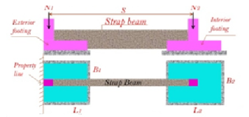
Fig no 17 Strap beam
Three basic considerations of the design of belts are:
1. The strap should be tightened possibly with Strap / Footing> 2. This strap is needed to control the rotation of the outer foot.
2. Footings should be approximately approximate equal soil pressure and avoiding significant differences in B to reduce settlement
3. The belt should not touch the soil so that there is no soil reaction Cantilever or Strap Footings.
It is common to ignore the weight of the belt in construction. The belt should be adequately attached to the column and feet with the use of tires so that the foot and cords are unit. The foot is pointed in one direction. The rope beam is reinforced with a main reinforcement at the top between the columns and at the bottom below the inner foot
Design of Strap Footings
Summary of strap footing design is shown in the following steps.
1- Proportion footing dimensions.
Sum moments about the center of the interior column and obtain the soil reaction beneath the exterior footing.
Summation Mcol2 = 0
R1 (S- e) - N1 S = 0
Sum moments about the center of the exterior footing and obtain the soil reaction beneath the other footing
Summation R1 = 0
N2 (S-e) - R2(S-e) - N1 e = 0
Design of Strap Footings
Summation F= 0
N1 +N2 - R1 - R2 = 0
To solve these three equations assume a value of eccentricity, e. Find R1, R2 and check equation (3).
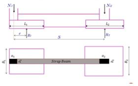
Fig no 18 Design of strap footing
1- Proportion footing dimensions.
Find the required area for each footing:
L1 = 2 (e + a1/2) and B1 = R1 / L1 * q all
A2 = R2 / q all A2 = B2. A2 = L2 * B2
!f B is too large or too small compared to L can be repeated until satisfactory dimensions are obtained. BI should not be greater than 1.5 LI
2 - Evaluate factor net soil pressure under the footing
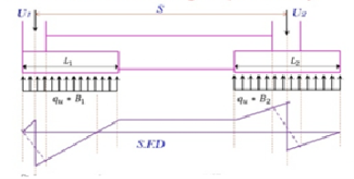
Fig no 19 3- BMD
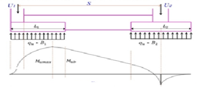
Fig no 20
4- Find the depth of the concrete.
Measure the working depth, dfeet (1) with 3 ways to pierce the shear under column (1) and walk (2) with 4 ways to shear under column (2)
Deep depth design, d, with the worst of two dimensions and wide share, find the wide square from the shear strength diagram.
5- Design foot reinforcement as tightening of both sides
a- Strengthening in the direction of L
Select the times (refer to the temporary drawing) and measure the required reinforcement.
a- Reinforcement in B- direction
S1 = B1 - b1/2. Mu1 = qu1 * s2 /2
S2 = B2 - b2/2. Mu2 = qu2 * s2 /2
Check the reinforcement and select bars.
6- Design strap as beam but check if it is a deep beam
a) Depth of strap beam
The shear is constant in strap beam. Assume that the width of the strap, b (with the smallest of column 1 and 2)
d = Vu strap /  c b
c b
b) Reinforcement of strap beam
Select the appropriate moment must strap Using moment, d, and strength of materials and estimate the reinforcement As
As = the total reinforcement in strap beam
c) Development of positive reinforcement moment at simple support and at point of inflection
Positive moment tension Reinforcement shall be limited to a diameter such that LD completed for fy by equation
M n /Vu + la >= Ld
Where
M n is nominal moment strength assuming all reinforcement at the section to be stressed to the specified yield strength.
Vu is factored shear force at the section.
La is embedded length of bar past point of zero moment but not exceed the greater of (d) or (12 db).
An increase of 30% in the value of MN /Vu shall be permitted when the ends of reinforcement are confined a comp. Reaction.
Key takeaways:
Design steps
1- Proportion footing dimensions.
2 - Evaluate factor net soil pressure under the footing
3- BMD
4- Find the depth of the concrete.
5- Design foot reinforcement as tightening of both sides
6- Design strap as beam but check if it is a deep beam
The retaining wall is a structure that is constructed and constructed to withstand the back pressure of the ground, where there is a desired change in ground height that exceeds the resting angle of the soil
- Gravity wall, cantilever retaining wall, sheet pile retaining wall, bored pile retaining wall, anchored retaining wall are the types of retaining wall are often the types of retaining wall are the types of retaining walls are commonly used.
- Strong storage walls that do not allow to be made are often made as gravity walls. These walls are large in size. However, large gravitational walls may not be operational due to economic and spatial constraints.
- Also, in some cases, adequate pouring of solid cantilever walls can be allowed due to site constraints, and these walls need to be built with higher ground pressures, rather than active ground pressures. One way to deal with these issues is to reduce the focus from the wall.
- There are many ways to reduce the pressure on the ground, such as using a small weight gain. An effort has been made to understand the function of the cantilever wall with auxiliary shelves and therefore to evaluate the performance of the shelves to reduce ground pressure and bending time on the wall.
- The pressure relief shelf is a small cantilever platform with a limited width, extending to the rear angles at right angles, throughout the length of the retaining wall, monolithically constructed with a retaining wall stem.
- The use of an aid shelf not only reduces the pressure on the outside world but also provides economic stability and increases overall stability.
- Klein provides two separate ground pressure distributions namely the non-expanded shelf in the split line (short shelf) and the extended shelf in the split line (long shelf).
- The parameters affecting the structure of a cantilever wall with shelves are the number of shelves, the shape of the shelves and the width of the shelves.
- This paper introduces a parametric study of these factors affecting the construction of a wall using shelves. An effort is being made to find the best shelf space and the right width of shelves by looking at the effect of a short shelf and a long shelf.
- The differences between the base pressure (Pmax) and the minimum pressure (Pmin) in the base are also investigated.
Overturning is one of the limitations of wall stability. In order to improve this post-rear-force analysis it must be tested against the surface of the allocated surface called the thrust surface, usually on the gravitational wall behind the wall, and on cantilever walls it is considered to be a vertical plane
Although Danilevsky (1982) examined the problem in terms of common terms, the stability of anti-displacement walls has been positively assessed by the safety type F, which is defined as the ratio between the resistance times and the number of turning times relative to the toe. So with the simple cases of Fig. 1, the security item is provided by
F = Wx / Sa d
Where W = the weight of the wall and the soil between the wall and the focus area; Sa = active focus; and x and d = their arms, respectively.
Calculations are usually made using straight and vertical parts of the S, (called Sa and S, respectively). For this purpose, the upper part of the active focus can be considered in two different ways: such as reducing the moment of overturning
F = Wx / Sah ys – Sav X's
Or increasing the resisting moment
F = W x + S a v x s / S a h ys
Where y s and X's = arms of S a h and S a v respectively. Both of these formulas are used in the analysis of wall durability
(Huntington 1957). However, they are fundamentally different. The value of the security feature provided by (3) remains a positive number, and that (2) may divert or subtract negative numbers. Moreover, only (2) is the direct result of (1), while (3) corresponds to the incorrect change of one term from denominator to number.
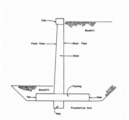
Fig no 21 Cantilever retaining wall
Main Features -
- Calculate the coefficients of global pressure based on Rankine's theory and Coulomb's theory.
- Calculate the force of gravity on the side that works on the wall.
- Wall analysis to test various conditions of durability and calculate safety Factor
- Calculate the horizontal coefficients according to India's standard code IS: 1893.
- Calculate the coefficients of seismic pressure according to IS: 1893, cl. 8.1.
- Perform soil analysis using a simulated method of analyzing soil pressure.
- Design of reinforcement of various wall materials.
Assumption
- The granular regression is considered analysis, meaning that there is no cohesion in the regression soil.
- Appropriate pipes are considered to be provided by the designer so that no hydrostatic pressure is built up behind the wall.
- It is assumed that the distribution of the triangular pressure is formed behind the wall due to the filled earth.
- All ground pressure winds are considered to operate on a vertical plane, passing behind the base of the base slab.
- The inclination of the wall and the friction angle between the wall and the reverse, it is assumed that there is no zero in this
Design Parameters:
Height of earth to be retained, h (m)
Surcharge pressure on backfill, W s (kN/m2)
Soil Properties: ...
Angle of internal friction of soil, φ (°)
Slope of backfill, β (°) with the horizontal.
Unit weight of soil, in kN/m2
Soil-wall interface friction, δ (°)
Concrete density, in kN/m2
Key takeaways:
Features
Calculate the coefficients of global pressure based on Rankine's theory and Coulomb's theory, force of gravity on the side, reinforcement of various wall materials, Coefficients of seismic pressure.
References:
- Reinforced concrete –limit state design by A.K Jain
- Reinforced concrete design by P Dayaratnam