Unit - 4
Design of beams
Beams are structural elements subjected to transverse loads in the plane of bending causing bending moments and shear forces.
Symmetrical b sections about z-z axis (major axis) are economical and geometrical properties of such sections are available in SP (6).
The compression flange of the beams can be laterally supported (restrained) or laterally unsupported (unrestrained) depending upon whether restraints are provided or not.
The beams are designed for maximum BM and checked for maximum SF, local effects such as vertical buckling and crippling of webs and deflection. Section 8 (IS 800-2007) shall be followed in the design of such bending members.
Beams can be different cross sections depending on the span and loadings.
1. Simple I section
2. I section with cover plate
3. Two I section with cover plate
4. Built-up I section
5. Gantry girder
6. Box sections
7. Castled beams
8. Two I placed one above the other
1) Simple I section: Use of simple I section is normal span and loading
2) I section with cover plate: Use of I section with cover plate is heavy load and larger span
3) Two I section with cover plate: it is use of very heavy load with large span
4) Built-up I section: it is used to plate girder where span exceed 20 m and loads are heavy.
5) Gantry girder: Gantry girder is use for movable heavy loads, lift loads etc.
6) Box sections: It is use for service lines
7) Castled beams: It is use for light loads and large span
8) Two I placed one above the other: It is used for light loading with large span
Key takeaways:
1) Simple I section: Use of simple I section is normal span and loading
2) I section with cover plate: Use of I section with cover plate is heavy load and larger span
3) Two I section with cover plate: it is use of very heavy load with large span
4) Built-up I section: it is used to plate girder where span exceed 20 m and loads are heavy.
Simply defined, lateral balance is the belongings of an item to broaden forces or to have forces imposed upon it that repair it to or keep its authentic condition (position).
Lateral balance is normally supplied for a beam, a column, a metal or timber frame, or a wall with lateral bracing.
Lateral balance is usually supplied for a beam, a column, a metal or wooden body, or a wall with lateral bracing.
Lateral bracing is the structural thing that stops the beam or column from twisting or buckling sideways or the structural thing that stops the metal body, wooden body, or wall from falling over.
In the case of a beam, the pinnacle of the beam is frequently laterally braced with the aid of using joists (open internet metal joists that seem like trusses or I- or C-formed member) that body into the facet of it or with the aid of using attaching the ground deck or roof deck to the pinnacle of the beam.
A column is usually braced within side the lateral route with the beams that body into its sides.
The lateral bracing for a metal body, a wooden body, or a masonry wall is commonly offer intermittently with the aid of using the ground deck or close to its pinnacle with the aid of using the roof deck in mixture with diagonal bracing and/or move walls.
Lateral bracing prevents a metal body, a wooden body, or a masonry wall from falling over below its very own weight or throughout publicity to an effect or wind pressures.
It is uncommon for a beam, a column, a metal or wooden body, or a wall in a finished shape to be inadequately braced within side the lateral route due to the fact they may be commonly deliberately or inadvertently braced with the aid of using the adjoining structural additives formerly mentioned. However, lateral instability isn't always unusual throughout the development or demolition levels.
During those levels lateral balance ought to be taken into consideration and brief lateral bracing supplied wherein necessary.
Lateral bracing is usually supplied throughout the volatile levels with brief man wires, diagonal braces, X-bracing, bracing to a close-by finished shape, etc.
The lateral torsional buckling is the deformation of the beam due to the applied loads away from its longitudinal axis. Further, it causes steel beams failures. The deformation could occur as translational and rotational movement of the section, and these types of movements are identified as lateral torsional buckling.
The lateral torsional buckling is the deformation of the beam due to the applied loads away from its longitudinal axis. Further, it causes steel beams failures.
The deformation could occur as translational and rotational movement of the section, and these types of movements are identified as lateral torsional buckling. Figure 1 indicates the deformations that can be seen as a result of lateral torsional buckling.
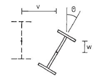
Figure: Lateral Torsional Buckling
As indicated in Figure, the beam can be decoded with the application of loads. This deformation could occur laterally and vertically with a rotation of the member. In the design of steel beams, lateral restrains are provided in spacings calculated to avoid failures.
Lateral torsional buckling occurs with the increase of loads based on section properties and it restrains. Loading on a beam cannot be avoided as it is the purpose of having the beam.
However, the section properties and the restrain conditions can be controlled during construction and design.
As discussed above too, lateral-torsional buckling occurs when the beam is not full restraints in the lateral direction along the compression flange of the beam.
The beam is considered full restraint laterally when the connection between the beam and the floor can resist at least a lateral force of 2.5% of the maximum force in the compression flange of the beam.
When there are no restraints, it is required to provide sections having higher section modulus, if the restraints are provided properly, the size of the beam can be reduced.
It is a proven fact that failures cause the moment of the section away from its axis. Therefore, providing the restrains will definitely reduce the section dimensions.
However, based on the structural arrangement of the structure, there may not be able to provide the lateral restrains at ends or internally. In such situations, beams need to be designed without considering the lateral restrains.
Mainly, the failures to restrain the compression flange cause the lateral movement of the section. Therefore, lateral-torsional buckling can be avoided by providing internal restrains.
Intermediate restraints are provided to reduce the unsupported length in the lateral direction. They should be capable of resisting lateral forces and should have the capacity to retain without deforming. The axial capacity of intermediate restrains shall be checked as per the guidelines in the BS 5950.
Design for Lateral Torsional Buckling of Beam
Section to satisfy the bending requirements, it shall have the bending capacity in the direction of bending (Mc) greater than the applied bending moment and lateral torsional buckling capacity greater the moment generated due to the buckling.
Mx < Mb/mLT and Mx ≤ Mc
In this article, the procedure needs to be followed in calculating the lateral-torsional buckling capacity is discussed. And the article steel beam design to bs 5950 could be referred bending capacity checks.
Lateral Torsional Buckling resistance (Mb/mLT) can be calculated as illustrated below.
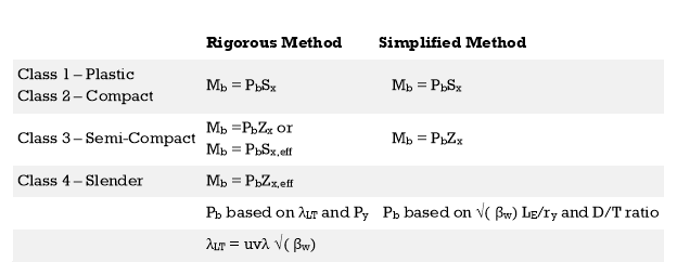
Two methods used to evaluate the Buckling Resisting Moment (Mb). Based on the preference of the designer, either method could be used.
- Rigorous method
- Simplified method
When both methods are compared, it seems that the main difference is the method of evaluating the Bending Strength (Pb).
A detailed explanation of the method of designing as a steel beam is discussed in the article steel beam design worked example.
Check Lateral Torsional Buckling
Lateral torsional buckling Example
Data:
- Consider simply supported beam with not intermediate restraints
- Beam span 6m
- Maximum design bending moment 100 kNm
As discussed above there are two methods for checking the lateral-torsional buckling. Let’s discussed them with a worked example.
It is required to satisfy the following equation for a section to be ok for buckling.
Mx < Mb / mLT
For simplicity, in this example, no intermediate restraints are considered.
Then,
MLT = 0.925, Table 18, BS 5950
Mb = Pb Sx Cl. 4.3.6.4
Firstly, let’s check the buckling capacity with rigorous method.
The following section data are considered in the calculation
- D = 500 mm
- T = 16 mm
- t = 10 mm
- B = 200 mm
- b = 100 mm
- r1 = 20 mm
- d = 500 – 16 x 2 – 2 x 20 = 428 mm
- Sx = 2175×103 mm3
- Zx = 1914×103 mm3
- Ry = 43.3 mm
- Section is plastic as per its dimensions
Rigorous Method
Mb = Pb Sx
Pb is function of λLT and Py
λLT = uvλ√(βw)
λ = LE / ry
LE – can be found from Table 13 (Cl. 4.3.5.1) and consider LLT = L – span
Thus,
LE = 1.0 LLT = 1 x 6 = 6 m
λ = LE / ry = 6000 / 43.3 = 138.568
For rolled I and H sections, Cl. 4.3.6.8
x = D / T used with u = 0.9
x = D / T = 500 / 16 = 31.25
βw can be obtained from the Cl 4.3.6.9
βw = 1 for Class 1 plastic or Class 2 Compact sections
v – Slenderness factor – obtained from Table as per the λ / x and η
λ / x = 138.568 / 31.25 = 4.434
For equal flanges η = 0.5
v = 0.84 from Table [conservative value taken; λ / x = 4.5, interpolation shall be used for exact value]
λLT = uvλ√(βw) = 0.9 x 0.84 x 138.568 x √ (1) = 104.8
λLO to be obtained from Table 16 (indicated at the bottom of the Table)
If λLO ≥ λLT; Pb = Py or Otherwise Pb shall be taken from Table for rolled sections.
If λLO ≥ λLT no allowance needs to be made for lateral-torsional buckling and otherwise check for lateral-torsional buckling.
Py = 275 N/mm2;λLO = 34.3
λLO <λLT
Hence, check for lateral torsional buckling
From Table, for λLT = 104.8; Pb = 117 N/mm2
Mb = Pb Sx = 117 x 2175 x 103 x 10-6 = 254.5 kNm
Mb / mLT = 254.8 / 0.925 = 275.4 kNm
Therefore, Mx = 100 kNm < Mb / mLT = 239.838 kNm
Section is adequate for lateral torsional buckling as per the rigorous method.
Simplified Method
We need not doing both the calculation to check the buckling resistance.
Mb = Pb Sx: Cl. 4.3.7
The determination of the Pb is not the same as the rigorous method.
This method provides conservative answers.
Pb can be obtained from Table 20 of BS 5950 as per √(βw) (LE / ry) and D / T
βw = 1; as previous calculation.
LE / ry = 138.568; from above calculations
√(βw) (LE / ry) = 10.5 x 135.568 = 138.568
D / T = 500 / 16 = 31.25
Now, can obtain from Table 20
Pb = 116.646 N/mm2
Mb = Pb Sx = 116.646 x 2175 x 103 x 10-6 = 253.705 kNm
Mb / mLT = 253.705 / 0.925 = 274.3 kNm
Thus, Mx = 100 kNm < Mb / mLT = 274.3 kNm
Therefore, the section is adequate.
Key takeaways:
1) The lateral torsional buckling is the deformation of the beam due to the applied loads away from its longitudinal axis.
2) Further, it causes steel beams failures. The deformation could occur as translational and rotational movement of the section, and these types of movements are identified as lateral torsional buckling.
3) The lateral torsional buckling is the deformation of the beam due to the applied loads away from its longitudinal axis. Further, it causes steel beams failures.
1. Shear strength:
Shear forces always exists with BMS and the maximum shear stress has to be checked with the shear yield stress. Shear stresses can become important if the depth of the beams are restricted and when beams are subjected to large concentrated loads near the supports The distribution of shear stress at limit state (plastic) is shown below

The nominal shear yielding strength is based on the Von Mises yield criteria which assumes wide and thin webs without any local failures. The shear strength is expressed as

Fyw = yield strength of the web
The design strength

Av = Shear area as specified in cl. 8.4.1.1 pg-59
The web can buckle elastically or in elastically depending on the ratio of d/tw if this ratio exceeds 67E
Where,
€ =  and d = clear depth of the web between flanges, resistance to shear buckling has to be verified
Shear failure can occur due to excessive yielding of the web area if the shear capacity is exceeded. The beam will be a high shear condition if V > 0.6 V, and the moment capacity of the section decreases and has to calculated using the provisions given in cl. 9.2.2 pg 70.
Key takeaways:
1) Shear forces always exists with BMS and the maximum shear stress has to be checked with the shear yield stress.
2) Shear stresses can become important if the depth of the beams is restricted and when beams are subjected to large concentrated loads near the supports.
3) Shear failure can occur due to excessive yielding of the web area if the shear capacity is exceeded. The beam will be a high shear condition if V > 0.6 V
1. Web buckling:
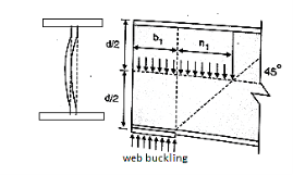
The web of the beam is thin and can buckle under reactions and concentrated loads with the web behaving like a short column fixed at the flanges. The unsupported length between the fillet lines for sections and the vertical distance between the flanges or flange angles in built up sections can buckle due to reactions or concentrated loads. This is called web buckling.
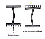
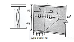
For safety against web buckling. The resisting e shall be greater than the reaction or the concentrated load. It will be assumed that the reaction concentrated load is dispersed into the web at 45" as shown in the Fig.
Let Resisting force F
Thickness of web = t
Design compressive stress in web =fcd
Width of bearing plate= b1
Width of dispersion = n1

For concentrated loads, the dispersion is on both sides and the resisting force can be expressed as, Fwb = [(b₁ +2 n₁) tw fcd] ≥ Concentrated load, P
The design compressive stress fd is calculated based on a effective slenderness ratio of 
Where,
d = clear depth of web between the flanges
Ry = radius of gyration about y-y axis and is expressed as,


Design compressive stress in web, fcd for the above slenderness ratio is obtained from curve, C (Buckling class C) (Table 9c, pg 42)
2. Web crippling:
Web crippling causes local crushing failure of web due to large bearing stresses under reactions at supports or concentrated loads. This occurs due to stress concentration because of the bottle neck condition at the junction between flanges and web. It is due to the large localized bearing stress caused by the transfer of compression from relatively wide flange to narrow and thin web. Web crippling is the crushing failure of the metal at the junction of flange and web. Web crippling causes local buckling of web at the junction of web and flange.
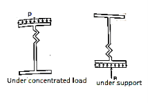
For safety against web crippling, the resisting force shall be greater than the reaction or the concentrated load. It will be assumed that the reaction or concentrated load is dispersed into the web with a slope of 1 in 2.5 as shown in the Fig.
Let Resisting force = Fwc
Thickness of web = tw
Yield stress in web = fyw
Width of bearing plate = b₁
Width of dispersion = n₂

For concentrated loads, the dispersion is on both sides and the resisting force can be expressed as,

Key takeaways:
- The web of the beam is thin and can buckle under reactions and concentrated loads with the web behaving like a short column fixed at the flanges.
- The unsupported length between the fillet lines for sections and the vertical distance between the flanges or flange angles in built up sections can buckle due to reactions or concentrated loads
- Web crippling causes local crushing failure of web due to large bearing stresses under reactions at supports or concentrated loads.
- This occurs due to stress concentration because of the bottle neck condition at the junction between flanges and web.
A beam may have adequate strength in flexure and shear and can be unsuitable if it deflects excessively under the service loads. Excessive deflection causes problems in the functioning of the structure. It can harm floor finishes, cause cracks in partitions and excessive vibrations in industrial buildings and pending of water in roofs. Cl.5.6.1, 5.6.1.1 and Table 6 gives relevant specifications with respect to deflection.
The beam size may have to be taken based on deflection, if the spans and loadings are large. Typical maximum deflection formulae for simple loadings are given below:


Key takeaways
- A beam may have adequate strength in flexure and shear and can be unsuitable if it deflects excessively under the service loads.
- Excessive deflection causes problems in the functioning of the structure.
- It can harm floor finishes, cause cracks in partitions and excessive vibrations in industrial buildings and pending of water in roofs.
1. Laterally supported beams:
- Calculate the factored load and the maximum bending moment and shear force
- Obtain the plastic section modulus required
Zp = (M*Vmo /Fy)
A suitable section for the beam-ISLB, ISMB, ISWB or suitable built-up
Sections (doubly symmetric only). (Doubly symmetric, singly symmetric and asymmetric- procedures are different)
3. Check for section classification such as plastic, compact, semi-compact or slender. Most of the sections are either plastic or compact. Flange and web criteria.

4. Calculate the design shear for the web and is given by

5. Calculate the design bending moment or moment resisted by the section (for plastic and compact)

6. Check for buckling
7. Check for crippling or bearing
8. Check for deflection
2. Laterally unsupported beams
- Calculate the factored load and the maximum bending moment and shear force
- Design of LSB is by trial-and-error method. The design bending stress is significantly less which is to be assumed to start with. Assume slenderness ratio and h/tf and get the corresponding critical bending stress and hence the corresponding design bending stress.
- Determine the required plastic section modulus and select the section.
- Determine the actual design bending stress of this selected section knowing its slenderness ratio which should be greater than that assumed previously. Otherwise revise the section.
- Check for shear, buckling, crippling and deflection should be done Design bending strength can be calculated as per IS: 800
Design bending strength can be calculated as per IS: 80


 rolled or welded sections
 can b Elastic lateral buckling,
Torsional constant, 
Warping constant, 
References:
- Design of Steel Structures- Limit State Method by N. Subramanian, Oxford University Press
- Limit State Design of Steel structures by S.K. Duggal, Mc-Graw Hill
- Design of steel structures by S.S. Bhavikatti, I.K. International Publishing house.
- Design of Steel Structures by K. S. Sairam, Pearson
- Steel Design by William T. Segui, Cengage Learning
- Fundamentals of Structural Steel Design by M.L.Gambhir, Mc Graw Hill
- Steel Structures-Design and Practice by N. Subramanian, Oxford University Press