Unit - 3
Purification
- At the source the water may have some suspended material of large or medium or small size, it is always economical to remove such suspended matter at the source by using the method sedimentation.
- The suspended matter makes the water turbid, so before it is carried for the further treatments, by using the sedimentation method, it is better to remove, such undesired impure material from the water.
Advantages of Plain Sedimentation:
- In this process the load is reduced. So the further process, it need less time and energy.
- After this process, less variable quality of water is made available.
- The clearing cost of the coagulation basis is reduced.
- There is not loss of chemical with the sludge. For the further processes, less quantity of chemical are required, so it reduces the cost of treatment.
Chemically Assisted Sedimentation:
- It is Chemically Assisted Primary Sedimentation (CAP) method. In this method some chemicals are used to increase the processes of coagulation flocculation and finally, the sedimentation.
- This method is applied mainly in the Urban Waste Water Treatment Plants (UWWTP).
Sedimentation Tanks and their Design:
- In the process of sedimentation, the inorganic impurities are removed and the water is kept ready for the further processes before it is used for the drinking purpose.
- The sedimentation tanks are designed for giving total rest or a partial rest to the flowing water.
- As the water is allowed to settle down, the heavy inorganic material also settles down on the bed of the tank, the remaining, lighter impurities are removed from the top of the tank.
- The amount of impurities removed from these tanks, depends upon various factors like, design of the tank, the period of detention, the particle's size, the actual velocity of the flow of water etc. On an average, in these tanks, about 60% of the suspended and 75% of the bacterial impurities are removed.
- To make the method more effective coagulants are added into the water, before placing the water in the sedimentation tanks.
- Finally from these sedimentation tanks, the water is allowed to pass through the process of filtration for the further purification of the water.
Type-l and Type-II Settling Basins:
- These basins are designed to hold water to allow the suspended matter to settle down. The technology to be used for settling depends upon, the specific gravity, size and the density of the particles and also the physical properties of the solid. There are four types of processes used for sedimentation.
- Type 1: Dilutes, non-flocculent, free-settling: In this, every particle settles separately and independently.
- Type 2: Dilute flocculent: In this the particles can flocculate, as the settle.
- Type 3: Concentrated suspensions; zone settling,hindered settling i.c. sludge thickening.
- Type 4: Concentrated suspension, compression i.e.sludge thickening.
Classification of Sedimentation Tanks/ Basins
On the basis of the nature of working, the sedimentation tanks can be classified as, fill and draw type tanks and continuous flow type tanks. Let us study the characteristics of each type of the sedimentation tank.
- Fill and draw type tank
- Continuous flow type tanks
1. Fill and draw type tank
- These tanks are also called as Quiescent type or Intermittent type of tanks.
- The process is very easy; these tanks are allowed to be filled to their capacity and the water is allowed to settle down for a given period of time, which varies on the basis of the size and capacity of the tank to hold water.
- Once the water gets settled, the suspended matter settles down on the floor of the tank and then the water is allowed to flow out of the tank.
- After water goes out of the tank, it is cleared by taking out the settled down silt water and are kept ready for another filling.
- If this method is to be used, which needs the rest period of about 24 hrs, it is necessary to have at least another tank for the continuous supply of water.
- Third tank as a standby is useful to run this method successfully.
2. Continuous flow type tanks
- The working of this type of tank is very easy. From one edge the impure water is flown into the tank and from the other end it goes out the velocity of the water is adjusted in such manner, that the suspended, impurities are allowed to settle down.
- When the an anlity of such impurities in a form of sludge or sill, becomes sizable, by using the valves at the bottom of the tank, it is cleared and cleaned for the next filling.
Design of the Sedimentation Tank / Fill and draw type:
- As shown in the Fig., the cubical contents of the tank represent the capacity to store the water to be treated. The bottom part has the arrangement to be called the silt and sludge.
- The inlet or the outlet valves are fixed in opposite directions the inlet near top of the tank and outlet valve is set near the top of the silt deposition zone, near bottom of the tank.

Fig. 1: Section
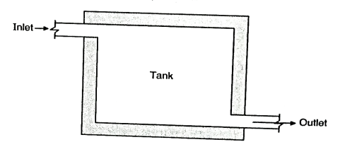
Fig. 2: Plan-Fill and Draw Type Tank
Efficiency of sedimentation:
Among all the factors controlling the efficiency of sedimentation two factors are important as given below:
- The velocity of water: If the velocity is brought to zero i.e. it the water is stable by gravity the suspended solids settle down easily.
- The type of suspended solids: The efficiency depends up of the proportion and type of solids.
Continuous flow type:
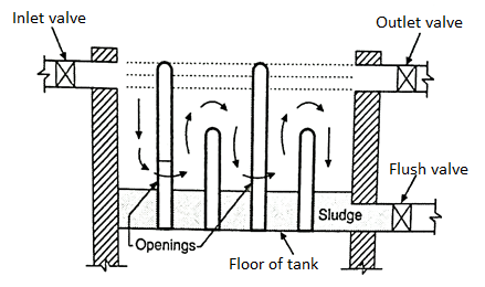
Fig. 3: Section
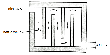
Fig. 4: Plan- Continuous Flow Type Tank
- As shown in Fig. In this method, the tank has the inlet on one side and out let valve on the other side. They are placed at the same level.
- They are separated by baffle walls creating separate chambers. At the bottom of the tank the arrangement is made to settle the sludge and silt. Tops
- After a given period of time the sludge is taken out through the flush valve which is kept at the bottom level of the tank.
Design of Sedimentation Tank / Horizontal Flow:
Following are the various steps involved in the design of sedimentation tank having horizontal flow:
- Various assumptions in the design
- Detention time (
 )
) - Displacement efficiency (
 )
) - Flow through period (
 ).
). - Weir loading
- Zones in sedimentation tank
- Inlet zone
- Outlet zone
- Sludge zone:
- Settling zone
1. Various assumptions in the design
- Flow should be steady and uniform in the settling zone.
- The suspended particles should settle in the same manner as they settle in a quiescent tank within the settling zone.
- Particles reaching the sludge zone should be effectively removed.
- Incoming flow should be distributed uniformly over the cross-sectional area of the tank.
- The concentration of suspended particles of each size should be uniform throughout the cross section at right angle to the flow.
2. Detention time (to)
- The theoretical time for which the water is detained in the settling tank is called as detention time (t0).

Where, V = Volume of the tank = length x breadth x height
Q = Discharge of water
- Detention time varies from 4 to 8 hours and this variation depends upon type of suspended solids.
3. Displacement efficiency ( )
)
- The ratio of flow through period to the detention period is termed as displacement efficiency.
- Displacement efficiency varies from 0.25 to 0.5 for plain sedimentation tank. A flow through period (t) should be equal to at least 30% of the detention period (t) for well designed tank.
4. Flow through period (t)
- Actual time of travel of flow from the inlet to the outlet of settling tank is termed as flow through period.
- Because of short circuiting: td<to
5. Weir loading
- Water falling over the weir is called as weir loading. It is expressed as the quantity of water discharged per hour or per day per unit length of weir.
- Weir loading should not be more than 450 kilo litre/day/m in general.
6. Zones in sedimentation tank
- It is considered to have four zones in the tank for proper designing the sedimentation tank.
- Following are the four zones to be assumed and for the design of sedimentation tank.
- Fig. Show these four zones. In the vertical cross section of tank.
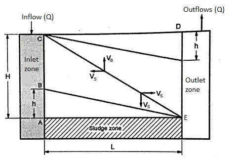
Fig. 5: Four Zones in the Vertical Cross Section of Sedimentation tank
(i) Inlet zone
- Raw water enters in the sedimentation tank through inlet zone.
(ii) Outlet zone
- Effluent water comes out from the sedimentation tank with residual turbidity through outlet zone.
(iii) Sludge zone
- Sediments settle at the bottom in sludge zone.
(iv) Settling zone
- Discrete particles settle down in settling zone under the force of gravity. In this zone, velocity of flow is low so as to have laminar flow and there is no turbulence.
Key Takeaways:
At the source the water may have some suspended material of large or medium or small size, it is always economical to remove such suspended matter at the source by using the method sedimentation.
Examples on Sedimentation Tank
Q. A settling tank is designed for an overflow rate of 5000 lit/m²/hr. What percentage of particles of diameter (i) 0.06 mm and (ii) 0.03 mm will be removed in this tank. Temperature of water is 20°C and specific gravity of particles is 2.65.
Soln.:
Given: Overflow rate (Q) = 5000 lit/m2/hr
Temperature (t)= 10°C.
Specific gravity (
d=Diameter of particles = 0.06 mm and 0.03 mm
Step 1: To find settling velocity ( )
)
Q = 5000 liters/hr
= ∵1
∵1
=
A=1
∴
Step 2: To find percentage of particles of diameter of 0.06mm and 0.03 mm to be removed
(a) For 10°C, Equation 
Reduces to  =418(Ss-1)
Where, V = Kinematic viscosity of water in centistokes
∴For 10°C,

= 2.48 mm/sec
= 0.248 cm/sec
∴% settled= ×100
×100
=
=179.71>100%
Hence all the particle of 0.06 mm diameter will settle.
(b) For 10°C, Vs’ =418 (Ss -1) d²
= 418 (2.65-1) (0.03)²
= 0.620 mm/sec
= 0.062 cm/sec
∴ % settled = ×100=44.92%
% settled particles of 0.03 mm is 44.92% and which is to be removed.
Q. Design a circular sedimentation tank fitted with mechanical sludge remover for water works, which has to supply water at the rate of 135 lpcd for population of 50000 persons. Use detention period as 4.5 hrs and water depth in the tanks as 3.3 metres.
Soln.:
Given: Population of the town = 50000 persons
Per capita demand= 135 litres/day,
Detention period=4.5 hrs
Water depth (H) = 3.3 m
Step 1: To find quantity of water to be treated
Quantity of water to be treated = 50,000 x 135 = 6.75 x 10⁶ liters/day
Step 2: Quantity of water to be treated by the sedimentation tank
Quantity of water to be treated by the sedimentation tank during detention period of 4.5 hours.

=1.265 x 10⁶ liters
=1265.625 cu.m ∵1m= 1000 liters
∴Q = 1266 cu.m say
Step 3: To find the diameter (D) of the tank
The capacity of circular tank having diameter D and water depth H is given by,
Q = D2 (0.011 D+ 0.785 H)
Q = D² (0.11 D +0.785 x 3.3)
1266 =D² (0.11 D + 2.5905)
1266= 0.011 D³ +2.5905 D²
∴0.011 D³ +2.5905 D² + 1266 = 0
Solving above equation, we get,
D = -237.53 and D = 1.019
D = -237.53 is not valid
D = 1.019= 1.02 m
D = 1.02 m
Step 4: To determine the size of tank
Providing an extra depth of 1.2m for sludge storage and free board, the size of the tank is 1.02 m diameter x (3.3 +1.2=4.5 m depth)
∴Size of the tank = (1.02 m diameter x 4.5 m depth).
- The word has been, derived from a Latin word 'flocculator', it means, to form a floc.
- Flocculation is stimulation by mechanical methods to collect destabilized particles into compact flocs. When these particles come in contact they become large and get settled in the form of flocs..
- The flocculation is the result of changes in the velocity of the water which is mixed with coagulant.
- This process takes place in the mixing basin also known as flocculation basin.
- It is common practice to provide the flash or rapid mix which is followed by the slow mixing.
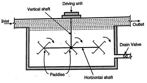
Fig .6: Flocculator
Design of Flocculator:
- See the Fig. Which shows the design of a typical flocculator. In this the slow mixing is achieved by rotating the paddles with two to three revolutions per minute.
- Sometimes the flocculator is combined with the sedimentation tank. This type of tank is known as coagulation sedimentation tank.
- A floc chamber is attached before the water enters in the sedimentation tank the period of detention in the floc chamber is about 15 to 40 minutes and detention period for the tank is about 3 to 4 hours. The cleaning of the tank is carried out after 3 to 6 months.
Important Terms - Design of Flocculator:
- Detention period
- Discrete particles
- Surface loading
- Mean velocity gradient
- Weir loading
- Flocculation
- Surface overflow rate
1. Detention period
- "It is the period of time given to settle the row water to settle down the impurities".
2. Discrete particles
- "It is size shape of the particles which varies between 10² and 10¹ cm."
3. Surface loading
- "It is process of mixing the chemicals for the precipitation of impurities".
4. Mean velocity gradient
- "It is the rate of change of velocity per unit distance normal to a section i.e. meter sec. Metre". So G (Gradient) is expressed as sec¹.
5. Weir loading
- If the water falls over a weir, through same out let it is called as weir loading. It is expressed as "The quantity of water discharged per day or per hour, per unit length of the weir.
6. Flocculation
- It is the result of changes in the velocity of the water which is mixed with coagulant.
7. Surface overflow rate
- "Surface overflow or surface loading is the quantity of water i.e. volume of water passing per day or per hour, per unit horizontal ara."
- Generally, in a case of the public water supply project; the source of water is the surface water.
- This water as it remains open, has a lot of impurities in the suspended form making it turbid.
- Sometimes the colour of the water also is changed due to colloidal matter and the dissolved organic material. So it has a turbidity due to clay, silt and some organic matter.
- Unless, such water is allowed to settle down for a longer period in the sedimentation tank, these impurities are not removed, or it can be done by making the size of the suspended water larger and bigger; to allow it to settle down.
- Coagulation means to add the chemicals, called as coagulant, which react with the impurities and convert them it to sizable and settleable volumes.
- This method of coagulation is used when the turbidity of water is more than 40 p.p.m. (parts per million). One must know that coagulation not, complete method of water purification. It helps to remove the impurities, when used in the plain sedimentation.
- It is necessary to follow the methods of filtration for the final removal of the impurities to make it safe and portable.
Theory of Coagulation / Principles of Coagulation:
- The base of the process of coagulation is that the stability of colloidal particles depends upon the electric charge which they have or they possess.
- The primary charge of the colloidal particle is due to the charged groups, which are within the surface of the particles or may be due to the process of adsorption of the layer of ions, from the surrounding medium.
- This primary charge gets counter balanced by the ions of opposite charge in the water phase.
- Between the water and the solid an electrical double layer is formed at the interface [Refer the Fig.]
- The double layer has,
- The charged colloidal Particles.
- The equivalent excess of oppositely charged counter ions they get accumulate in the water, near the surface of the particles.
- The counter ions are attracted electro-statically to the particle surface and they cause the high concentration at the particle surface.
- This diffusion or decrease of these counter ions, is due to the agitation and also due to replacement by other ions.
- When there is a high concentration of counter ions, in the water the diffused layer is compacted. It is known as the diffused double layer theory.
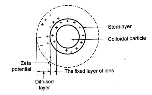
Fig. 7: The Diffused Double layer theory
Classification of Coagulants:
On the basis of the basic material the coagulants can be divided as follows:
- Aluminium sulphate
- Chlorinated copperas
- Ferrous sulphates and lime
- Magnesium carbonate
- Polyelectrolytes
- Sodium aluminate
Let us study the functions of each of the above mentioned coagulants used for treating the water.
1. Aluminium sulphate
- It is also called as 'Alum'. Its use in the water treatment plant is almost worldwide.
- It is supply in the form of flakes or in the form of solid lumps and while applying for the treatment, it is converted into a solution.
Advantages of Alum:
- It helps to reduce the bad odour, taste and also reduces the turbidity of the water. The price of Alum is low.
- The use of Alum does not require skill full workers to handle so the cost goes still low. Alum, after its reaction, creates almost crystal clear water.
- The floc formed by Alum, is very tough and does not break easily.
- The dosage of Alum depends upon the turbidity of water, pH value, temperature of water, colour and taste of water etc.
- The range of Alum requirement for the treatment varies between 5 30 milligrams per lit. And For the normal conditions of water the dosage is about 14 milligrams per lit.
Disadvantages of Alum:
- The sludge developed after the use of Alum is difficult to dispose off. It is also has been observed that this sludge cannot be used for filling the low lying areas.
- To maintain the pH value, together with alum, caustic soda or the lime is required to be added. This increases the cost of the process.
2. Chlorinated copperas
- It is the combination of Ferric Sulphate, Fe, (SO₂), and Ferric chloride, FeCl, which is called as chlorinated copperas.
- This combination is used to remove the colour of the water. The Ferric Sulphate has the effective, pH range between 4 and 7 (sometimes above 9) while Ferric Chloride has the effective pH range between 3.50 and 6.50 (sometimes above 8.50)
3. Ferrous sulphate and lime or alum
- The effective pH range is 8.50 and above. Its floc is heavier than the floc formed by alum. So it is more effective for the treatment, but its use needs to have skilled supervision for proper dosage.
- This increases the cost of the process.
4. Magnesium carbonate
- The magnesium carbonate when mixed with water together with lime, the compounds of calcium carbonate and of magnesium hydroxide are non sulbla in water, so both the found in the slurry. At present, the use of this coagulant is not very popular. But may in near future, it would be proved to a better solution for treating the water.
Advantages of Magnesium Carbonate
- As both, i.e. calcium carbonate and magnesium hydroxide are non-soluble, they can be collected from the sludge through water dissolved with CO, gas and can be recycled and reused. Depending upon the quality of water to be treated and the design of the plant, this coagulant can be recovered upto 80% to 100%. This reduces the cost of the material used for the water treatment.
- It not only removes the organic colour and reduces the turbidity but removes iron and manganese also.
- The floc formed in this treatment process is larger in size and it is heavier than the floc formed in the process where Alum is used as the coagulant.
5. Polyelectrolytes
- They are the polymers and on the basis of the charge they carry, they can be classified as anionic, cationic, and non-ionic. Among these only cationic polyelectrolytes can be used very effectively as the independent coagulant. While in cases of other varieties, they can be used together with Alum or any other conventional coagulants.
- In India polyelectrolytes are collected from the extract of Nirmali seeds. This type of deciduous plant, small in size is found in almost all the state in India but mainly in Andhra Pradesh, Konkan coastal region of Maharashtra State, Madhya Pradesh, Orissa and in West Bengal.
- The use of polyelectrolytes needs to have a skilled supervision because if the dose is more than required, it may affect the working of filters. We must note here that the use of these polyelectrolytes as the coagulants is still in the pilot stage and so they may prove to be a better alternative for other coagulants in future.
6. Sodium aluminate
- This coagulant, when mixed and allowed to dissolve with the water, reacts with the salts of calcium and magnesium and removes carbonate to remove the temporary hardness. It also helps to remove the non-carbonate to get the away with hardness permanently.
- The coagulant has the effective range of pH, varying between 6 and 8.50 (as the pH of normal water is 7, in case of this coagulant, the problem of adjustment of pH value does not arise.
- As it is costly coagulant, it is not used for the treatment of large volume of water. Generally it is used to treat the water, to be used for boiler as the floc by aluminium sulphate is not formed easily.
Key Takeaways:
Generally, in a case of the public water supply project; the source of water is the surface water. This water as it remains open, has a lot of impurities in the suspended form making it turbid.
- In the process of purification of water, the filtration is the most important stage. The water is allowed to pass through a thick layer of sand to remove all the remaining impurities of water to make it portable and to make it safe for drinking purpose. This process bring following changes in the water, which is getting treated.
- The suspended and colloidal impurities are removed from the water, to a great extent.
- The chemical characteristics of the water get changed.
- The proportion of bacteria in the water is reduced.
- These changes are the results of the four actions which take place during the process of filtration. They are as follows:
- Mechanical straining
- Sedimentation
- Biological metabolism
- Electrolytic changes
Let us study the functions of these actions in process of filtration:
1. Mechanical straining
- The suspended particles which cannot pass through the sand, are trapped and are removed by this action.
2. Sedimentation
- The void between the sand particles acts as a small size sedimentation tank and the impurities are arrested either due to coating developed on the sand particles by the colloidal matter saturated on the sand or by the physical attraction between two particles of any matter.
3. Biological metabolism
- The life process of any living cell is called as Biological metabolism. When any type of bacteria are caught in the voids of the sand particles a thin jell or a film is developed around the particles of sand having a very large number of bacteria which use the organic impurities as a food and convert them into harmless compounds to make the water safe for drinking.
4. Electrolytic changes
- When any two deflect particles have opposite electric charges are put together, the electrical charges are totally neutralized to develop a new chemical substance which is not harmful. They are needed to be removed by cleaning the filters to make it safe and portable.
Types of Filters:
- On the basis of the time required for the process of filtration; the filters are divided into two categories such as, slow sand filters and rapid sand filters.
- They are sub-groups of gravity filters. The third type of filter is known as pressure filters. Let us study these different processes of filtration.
- Slow sand filters
- Rapid sand filters
1.Slow Sand Filters
- To improve the biological, chemical and physical characteristics of the water to be purified, it is allowed to pass slowly through the layer of sand, which placed above the basic material.
- It is the most suitable method to purify the water supply to the rural areas because it is easy and needs less maintenance cost.
- The slow sand filters have the following necessary parts to carry the process, Enclosed tank, Under drainage system. Base material, Filter media of sand and Appurtenances.
- Let us study the functions of these parts in details.
- Enclosed tank
- Under drainage system
- Base material
- Filter media of sand
- Appurtenances
1. Enclosed tank
- A water tight tank is constructed by using either brick masonry or the stone masonry. The floor and the sides of the tank also are coated with the material which can make them water proof.
- The general slope is about 1: 100 to 1: 200, towards the direction of the central drain.
- The depth of the filter tank varies between 2.50 m and 3.50 m, and accordingly the surface are of the sand filter also changes from 30 m² to 2000 m² or even more as the depth would vary.
2. Under drainage system
- It consists of the central and lateral drains (see the open Fig.).
- These drains may be of pipes, which are laid with joints or may consist of other drain devices. The lateral drains are placed at a distance between 2.50 and 3.50 m and are stopped at a distance of about 500 to 800 m from the walls of the tank.
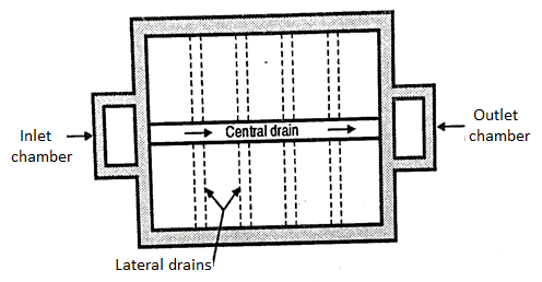
Fig. 8: Design of slow sand filter
- The lateral drains can be made by placing two rows by bricks and having two layers of bricks one above the first layer which act as the lateral drain.
3. Base material
- The base material of gravel is placed on the top of the under drainage system. The depth of the gravel material varies between 300 mm and 750 mm. The size of the gravels changes from the top to the bottom layer e.g. The top layer has the gravels having the size between 3mm and 6mm.
- In the intermediate layer, the size varies between 6 mm and 20 mm (in some cases it may have the size of the gravel between 20 mm and 40 mm). While in the lowest i.e. bottom layer.
- The size of gravel varies between 40 mm and 65 mm. Out of the total depth of the base material of gravel the top layer is about 150 mm, in depth, the middle or the intermediate layers. Cover 150+ 150 mm deep and bottom layer also is 150 mm deep. So the total depth of these layers is 600 mm.
4. Filter media of sand
- Above the layers of grave a layer of sand is placed. The depth of this sand layer varies between 600 mm and 900 mm and size of the sand particles also varies from 0.20 mm to 0.30 mm.
- Fine sand can be more effective to remove the impurities but the time required for the process is long and processes is slow.
5. Appurtenances
- To make the process more effective many appurtenances are used e.g. a vertical air pipe, moving through these layers, to improve the functions of the sand layers. The filters are suitable installed to maintain the rate of flow of water.
- To maintain the constant flow of water through these filters, an adjustable telescopic tube is used, which is adjusted manually to maintain the discharge of clean water.
2.Rapid Sand Filters:
- Though the slow sand filter has a lot of advantages and good for the rural water treatment plant, the greatest disadvantage of the slow sand filter is that it needs to have a large space of its installation (in the rural areas, space is not a major problem).
- So in the urban areas where the land cost are sky hill, that method becomes useless e.g. For a moderately populated town say about 15000, the area required for the installation of the slow sand filter plant is about 1000 m², and considering the future water demand and the space required for other attached equipment for water purification, about 2 2000 m would be necessary.
- So it would be too costly to follow the slow sand filtration method. So the rapid sand filtration method has been put to use.
A. Methods of Rapid Filtration
- The rate of filtration can be increased by using two different method such as-
- It can be achieved as increasing the size of the sand particles. This reduces the friction of sand particles with the moving water. This helps to gain high speed for the filtration.
- If the water allowed to pass through the sand, with pressure, its velocity increases and so the time required for filtration is reduced.
B. Design of the Rapid Sand Filters
- As shown in the Fig., it has five essential parts such as enclosure tank, under drainage system, base material, filter media of sand and appurtenances.
- Let us study the functioning of these parts.
- Enclosure tank
- Under drainage system
- Perforated pipe system
- Pipe and strainer system
3. Base material
4. Filter media of sand
5. Appurtenances
6. The initial and final head loss
1. Enclosure tank
- By using either of masonry or concrete a water-tight tank is constructed.
- The floor and sides of the tank also are made water tight by using water proofing material.
- With the surface area of the tank varies between 10 m² and 50 m2 and the depth between 2.50 m and 3.50 m. These units are arranged in series.
2. Under drainage system
- There are various types of under drainage systems, but among them the commonly used systems are as follows
- Let us see the functioning of these two under drainage systems.
(1) Perforated pipe system
- In this system, various lateral drains are attached to the central drain. These drains are made up of cast-iron. They are placed with the average distance between 150 mm and 300 mm.
- The pipes of the drains have holes with 10 mm diameter and having the angle of 30° between two holes. To control the rusting of the holes, brass bushings are used to protect the holes.
- This system of perforated pipe is very simple and need less cost also but it requires about 700 lits. Of water per minute - per m² of the filter area for the washing purpose.

Fig. 9:Plan of Underdrainage System
(2) Pipe and strainer system
- In this system also, there is a central drain system but instead of wholes, this system has strainers.
- It is a small pipe made of brass. It has holes on its surface but it is closed at the top. They are fixed on the top of the drain.
- A compressed air is used for washing the filters. It needs about 250 litres of water per minute per m² of the filter area, for washing. It is called as low velocity wash.
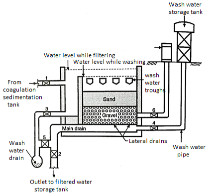
Fig. 10: Pipe and Strain system
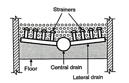
Fig. 11: Section of Under drainage system
3. Base material:
- On the top of the under drainage system, the base material i.e. gravel is placed. The size of the gravel varies between 3 mm and 6 mm in the top layer to 20 mm to 40 mm in the lowest level. The total depth of the gravel is about 600 mm.
4. Filter media of sand:
- Above the layers of gravel, the sand is placed. The adepth of sand layers varies between 600 mm and 900 mm. The size of the sand particles varies between 0.35 mm and 60 mm. As the space of voids increases, the rate of filtration increases.
5. Appurtenances:
- Together with the usual appurtenances used in slow sand filters, additional devices are provided for fast sand filtration e.g. Air compressor, wash-water troughs and venturi rate controller.
6. The initial and final head loss:
- In case of rapid sand filters, the initial head loss is 30 cm and final head loss is 3 meters. In case of slow and filters it is 15 cm and 100 cm respectively.
Key Takeaways:
In the process of purification of water, the filtration is the most important stage. The water is allowed to pass through a thick layer of sand to remove all the remaining impurities of water to make it portable and to make it safe for drinking purpose. This process bring following changes in the water, which is getting treated.
Problems on Filtration:
Q. For a town with population of 1 lakh; water is supplied at the rate of 200/lpcd.
Find out the dimensions of rapid sand filter by using the following data:
Rate of filtration = 6000 L/Hr/m2
Break through index = 1 x 10⁻³
Mean size of sand = 1 mm
Terminal head loss = 2.5 m
Also find depth of sand and water used for back washing.
Soln.:
Given:
Rate of filtration = 6000 lit/hr/m²
Bi = Break through index = 1 × 10⁻³
Population=1 lakh = 105
Mean size of sand (d)=1mm
H= Terminal head loss = 2.5 m
Rate of water supply = 200/lpcd = 200 lit per capita per day
Step 1: To find daily demand
Rate of water supply = 200 lit/hr/day
Daily Demand=Population x Rate of water supply
=105×200
=20×106lit/day
Step 2: To find hourly demand
Hourly demand=
Step 3: To find area of filter
Filtration rate= 6000 lit/hr/m3 (given)
Area of filter= 
Step 4: To find number of filter unit
Assuming size of filter as 7m x 5m
Number of filter units =140/35 = 4
Step 5: To find minimum depth of sand (l)
Minimum depth of sand= 
= =0.512
 2 =51.2cm
∴Provide 60 cm depth of sand.
Step 6: To find total depth of filter basin
Total depth of filter basin= Depth of under-drain+ Gravel depth + Sand depth+ Water depth + Free board
= 60+45+60+ 100+35
= 300 cm = 3m
∴Provide 4 units of filter, each of size 7m x 5m x 3m.
Step 7: To find quantity of wash water
Quantity of water = 2% filtered quantity used for back washing
= 2% daily demand=(2/100)×20×106=4×105 lit/day
(Assuming filters are washed once in 24 hours)
Q. Design six units of slow sand filter for the following data:
- Population to be served - 50,000 persons
- Per capita demand= 150 lit/hr/day
- Rate of filtration 180 lit/hr/sq.m.
Length of each bed - Twice the breadth. Assume maximum demand as 1.8 the average daily demand, also assume that one unit out of six will be kept as standby.
Soln.:
Given data for design
Population to be served = 50,000 persons Per capita
Water demand= 150 lit/hr/day
Rate of filtration = 180 lit/hr/m²
Length (L) of each bed= Twice the breadth (B)
L = 2B
∴
Maximum demand= 1.8 x Average daily demand.
Step 1: To find average daily demand
Average daily demand = Population X Rate of water supply
= 50,000 × 150 = 7.5 × 10⁶ lit/day
Step 2: To find maximum demand
Maximum demand = 1.8 x Average daily demand
= 1.8x7.5x 106
= 13.5 x 10⁶ lit/day
Step 3: To find discharge per hour
Discharge (Q) per hour = 
Step 4: To find surface area for filtration
Rate of filtration = 180 lit/hr/m² (given)
Surface area required for filtration = 
Step 5: To find area per unit of filter
Six units of filter are to be provided including 1 unit as standby. Note that while finding the area per unit of filter only 5 units are to be considered.
Area per unit of filter= 3125/5 = 625 m²
Step 6: To find length and breadth
L/B=2
∴L = 2B and Area A = 625= L x B= 2B x B= 2B²
Solving, B = 17.7m, L=2B = 2 x 17.7 = 35.5 m
∴Provide 6 units of size 35.5m long x 17.7 m wide.
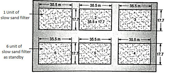
Fig. 12: Layout of slow sand filter
- After the process of filtration is completed, the water stall can have same impurities like Bacteria, Dissolved inorganic salts colour, odour and taste and iron and manganese.
- So it is necessary to disinfect the water before it is sent for the consumption through the distribution system.
- The method of disinfection is different than the method of sterilization. In case of disinfection, only the harmful bacteria are killed while in case of sterilization, both harmful and harmless bacteria are killed.
Disinfectants:
- It can be defined as "It is a process of cleaning water to destroy bacteria and all the microorganisms and also to prevent their growth, to make the water safe for consumption.
- Following factors affect the efficiency of the process of disinfection
- Physical factors
- Biological factors
- Type of disinfectants
1. Physical factors
- The temperature, pH, humidity and hardness of water affect the efficiency of disinfection.
2. Biological factors
- The number and location of the microorganisms, their resistance affect the efficiency of disinfection.
3. Type of disinfectants
- The concentration and potency of the Disinfectants also affect the efficiency of disinfection.
Types of Disinfectants
Following disinfectants are commonly used for disinfection of water.
- Sodium Hypochlorite
- Chlorine dioxide
- Peracetic acid
- Quaternary Ammonium compounds
- Iodophors
- Amphoterics
- Biguanides
The material used to disinfect the water is called as disinfectants.
The basic qualities of the disinfectants are as follows:
- It is dose should give protection against the contamination of water during conveyance and also during retention.
- It must be effective to kill all the harmful bacteria to make the water safe for consumption.
- It should be harmless, economical and should be easily available.
- Its nature should be such that its strength can be easily determined.
- Its use should not need to have skilled labour (which increases the cost of the disinfection the water).
- It should work at a normal temperature and should take a reasonable time, for disinfecting the water.
Minor Methods of Disinfection:
The following methods are used for disinfection of water:
- Boiling
- Excess lime treatment
- Iodine and bromine treatment
- Ozone treatment
- Potassium permanganate treatment
- Silver treatment
- Ultra-violet treatment.
Key Takeaways:
The method of disinfection is different than the method of sterilization. In case of disinfection, only the harmful bacteria are killed while in case of sterilization, both harmful and harmless bacteria are killed.
- It is a known fact that if the natural water has the salts if calcium and magnesium, which make the water 'hard'.
- Infact the hard water is not harmful to the human health but when it is used for often purposes like, washing the garments, in dying system, it needs to have more soap, more fuel for boiling and it make the food tasteless.
- So it is necessary to treat the hard water to make it 'soft' before it is put the other usages.
Classification of Hardness:
- On the basis of the duration of the hardness of water it can be classified as Temporary hardness and Permanent hardness.
- The temporary hardness of water is technically called as carbonate hardness. It is result of the presence of bicarbonates of calcium and magnesium.
- The permanent hardness of water is called as non carbonate hardness. It is the result of the presence of Sulphates, Chlorides and Nitrates of Calcium and Magnesium.
Removal of the Hardness of Water:
- The temporary hardness of the water can easily be removed either by boiling it or by adding lime. Both, calcium carbonate and magnesium carbonate are not soluble in water, so they easily can be removed in the sedimentation tanks.
- When a large volume of water needs to be treated to remove the hardness, boiling is not practicable. So the mixing of lime is the best method to remove the temporary hardness of water.
- Removal of the permanent hardness of water is not easy.
- It needs to have a special treatment, which is called as water softening treatment different methods can be used to remove the permanent hardness of water, which are as follow.
Lime-Soda Process
- In this process lime and soda ash i.e. sodium carbonate are used to remove the hardness of water. The hardness is brought down by 3° to 4°, by this method.
- The equipments necessary for this process are:
- Feeding and mixing apparatus
- Settling tank
- Recarbonation plant
- Filters
- In this process, following steps are taken:
- In addition to lime and soda ash, the aluminium compounds are mixed with the water.
- If necessary some more lime is added which precipitates magnesium.
- The next step is to neutralize the extra lime added in the water by the action of carbon dioxide. It is called as Recarbonation.
- A part of the water under treatment is taken separately and is given as excessive treatment and this water brought to the lowest level of hardness is mixed with the rest of the raw water to remove the total hardness.
- This split method saves time and also the chemicals and reduces the cost of removal of hardness of water. It can remove hardness upto 50 mg per lit. So it does not provide zero hardness.
Zeolite Process:
- This process is also called as Base-Exchange or Ion Exchange process. The zeolites are the compounds aluminium silica and soda.
- They are available in the nature or they can be produced synthetically. The natural zeolite is green in colour, so it is called as green sand. The exchange value of this green sand about 7000 gm to 9000 gm per m³ of zeolite.
- The synthetic zeolite is produced from felspar, kaolin clay and soda. These chemicals are mixed as per the requirement and they are fused in a furnace after a given time it is allowed to cool down. Then it is crushed to convert it into solid particles with a climate varying between 0.25 mm and 0.50 mm. It is washed to remove the impurities and alkalies. It is known as Permutit. It is white in colour.
- The exchange process needs about 8 to 10 hours. It is called as regeneration process.
Demineralization Process:
- In this method the hard water is allowed to pass through a bed of Resin or carbonaceous material which is in hydrogen form.
- The treated water contains diluted carbonic acid, sulphuric or hydrochloric acid. They are removed by mixing the treated water with alkaline water, with required proportion.
- After a given interval, the hydrogen content of the material gets exhausted. Then it is regenerated by passing a solution, of required strength, of sulphuric acid or hydrochloric acid.
- This process is mainly used for demineralising water, to be used for the industrial purpose.
Purpose of Aeration:
- In this method the water to be treated is brought in close contact with air. The aeration method has the following advantages.
- Upto same extent, due to agitation of water in the acration process, some of the bacteria get killed.
- In this process the oxygen is absorbed and carbon dioxide is released.
- It reduces the percentage of CO₂ upto 70% and this helps to reduce the chances of corrosion of the water carrying pipes.
- As hydrogen sulphide is easily removed in this process, the odour is removed. The iron and manganese in the water also is oxidized in the process of aeration.
Limitations of Aeration Method:
- Aeration method has the following limitations:
- Aeration method cannot remove 100% CO₂ so its residue always remains in the small quantities i.e. upto 3.5 mg/litre.
- Excessive aeration leads the excessive absorption of oxygen which leads to the increase the property of corrosiveness of water, which needs to have de-aeration process.
Methods of Aeration:
Following are the methods used to treat the water:
- Air diffusion
- Cascades
- Spray nozzles
- Trickling beds
1. Air diffusion
- In this the perforated pipes are fit at the bottom of a tank and the compressed air is made to blow through the perforated pipes.
- The aeration of water is activated when the air bubbles start passing in the upward direction.
- The depth of the aeration tank varies between 2.5m and 3m and the period of detention is about 15 minutes. About 0.3m³ to 0.6m³ air , consumed for the quantity of 1000 liters of water.
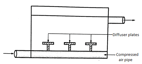
Fig. 13: Air Diffusion
2.Cascades

Fig. 14: Cascades
- It is free fall of water. The water is allowed to fall at a height of 1 to 3m. And the water runs in the downward direction over three or four steps, made up of cement or metal.
- When the water mixed with air, gets purified; when it reaches the ground level.
3. Spray nozzles
- The water is sprinkled through the nozzles upto the height between 2m and 2.5m.
- This method is very useful to remove about 90% of the carbon dioxide.
- This needs to have a large head of water for its working.
- The nozzle operation needs to have the pressure of about 0.07 to 0.14 N/mm².

Fig. 15: Spray Nozzles
4.Trickling beds
- In this method beds of coke or slag, supported by the perforated trays are prepared.
- These beds are arranged, one above the another in a vertical direction.
- The bed, containing the cokes with the average size of 50 to 75 mm has the average depth of 225 mm.
- The vertical distance between each bed is about 100 mm to 150 mm.
- The water carried by the pipes is allowed to trickle down through the beds. By this method, due to aeration, better results are achieved than the cascades.
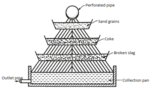
Fig. 16: Trickling Beds
Design of Aeration Fountain (Cascade Type)
- The method by which the maximum area of water is exposed to the atmospheric air, is termed as aeration.
A. Principle aeration
- Principle of gas transfer is being used in the aeration process.
B. Purpose
- To absorb more oxygen
- To prevent unpleasant odours and gases
- To oxidise Fe and Mg in water.
C. Design
Following are the various points to be considered in the design of aeration fountain (cascade aerator):
- Design flow i.e. discharge 'Q' is considered.
- To find and Assume suitable loading rate.
- To determine Area required for aeration fountain.
- To determine Inner diameter and outer diameter of circular type of aeration foundation.
- To determine the size of collecting channel outside the aeration fountain.
- To find area of Aeration launder by adopting the suitable velocity.
Key Takeaways:
In this method the water to be treated is brought in close contact with air. The aeration method has the following advantages. Upto same extent, due to agitation of water in the acration process, some of the bacteria get killed.
Examples on Design of Aeration Fountain
Q. Maximum daily demand of water in a city 125 MLD. Design cascade aerator for the same. Draw plan and elevation of the aeration fountain. Assume the inlet pipe diameter as 1.1 m.
Soln.:
Given: Discharge Q= 125 MLD, D= Diameter of the inlet pipe= 1.lm
Design steps
1.To determine the discharge (Q) in m3/hr cascades
Q = 125 MLD (given) = 125 x 106 liter/day ... 1 MLD = 10 liter
 …..∵1m3=1000liter and 1 day =24hrs
2. To determine area required
Assume loading rate as 0.04 m²/m³/hr
A = Area required=Q x loading rate = 5208.33 x 0.04
A = 208.33 m²
3.To determine total area of unit required
D = Diameter of the inlet pipe
(i.e. size of central shaft) = 1.1 m (given)
∴Total area of unit required = A + D²
= 208.33+(1.1)² = 208.33+0.950=209.28 m²
4. To find outer diameter of unit required
Outer diameter of unit required= = 16.3 m
5. To determine number of cascades
Consider tread as 1.1m and rise as 0.2m.
∴Number of cascades =
Hence provide 7 cascade with tread of 1.1m and rise of 0.2m.
6.To find diameter of bottommost cascade
Diameter of bottommost cascade = (2x1.1x7) + Inlet diameter =15.4+1.1= 16.5 m
7. To determine the size of collecting channel outside.
Design flow (peripheral) = = 62500 m3/day 2
= =0.72m3/sec
8.To determine the size of launder
Adopt the velocity of 1m/sec;
Area of aeration launder = 0.72/1=0.72m3
Provide a launder of 1.0 mx 0.72 m.
9. From the above calculated design data, draw the Fig.(a).
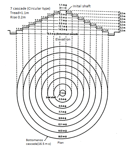
Fig. 17: Aeration Fountain (Cascade Type)
Fig.(b) shows the idea about the aeration fountain (circular type).
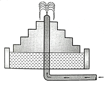
Fig. 18: cascade aeration fountain (Circular Type)
Q. The maximum daily demand of water is 115 MLD. Design aeration fountain (cascade aerator). Consider loading rate as 0.03 m²/m²/hr.
Soln.:
Given: Discharge, Q=115 MLD.
Loading rate=0.03 m²/m3/hr
Design steps:
1.To determine the discharge (Q) in m3/hr cascades
Q = 115 MLD (given)
=15 x 10° liter/day ..... 1 MLD = 106 litre
= ….∵1m3=1000liter and 1 day=24hrs
2.To determine area required
Assume loading rate as 0.03 m²/m³/hr
A = Area required= Qx loading rate= 4791.66 x 0.03
A = 143.749, say 144 m²
3. To determine total area of unit required
Assume, D = Diameter of the inlet pipe = 1.1 m (i.e. size of central shaft) = 1.1 m
∴Total area of unit required= A +  D²
D²
= 144 + + (1.1)² = 144+0.950=144.95 say 145m2
4. To find outer diameter of unit required
Outer diameter of unit required =
5. To determine number of cascades
Consider tread as 1.1m and rise as 0.2m.
∴Number of cascades = = 
Hence provide 6 cascade with tread of 1.1m and rise of 0.2m.
6. To find diameter of bottommost cascade
Diameter of bottommost cascade = (2x1.1 x6) + Inlet diameter = 13.2 +1.1 = 14.3 m
7. To determine the size of collecting channel outside the aeration fountain
Design flow (peripheral) = 57500 m m²/day=
 =0.66m3/sec
8.To determine the size of launder
Adopt the velocity of 1m/sec;
∴Area of aeration launder = 
Provide a launder of 1.0 m x 0.66 m.
9.From the above calculated design data, draw the Fig.
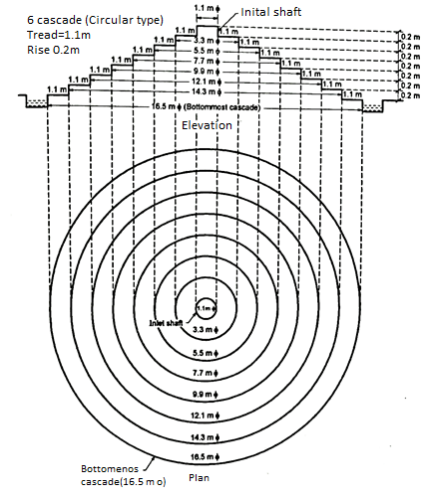
Fig. 19: Aeration fountain (cascade type)
Process of Reverse Osmosis:
Before we talk about the process of reverse osmosis we must know what is the process of osmosis.
Process of Osmosis:
- It is natural process of fluid flow across the semi permeable membrane barrier [Refer Fig.]
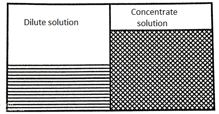
Fig 20: Osmosis
- As shown in a tank one side has pure water and other side has salty concentrate solution.
- Due to change in pressure and temperature the diluted solution would move towards the concentrated solution to reduce the salts.
Process of Reverse Osmosis:
- If an external pressure to the salt concentration solution is provided the equilibrium would be developed.
- This additional pressure will raise the chemical potential of the water in the salt solution and will cause a solvent flow to the pure water side as it has a lesser chemical potential. This process is called as Reverse Osmosis.
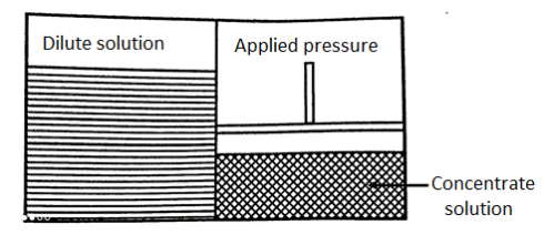
Fig. 21: Reverse Osmosis
Removal of Iron and Manganese:
- The rain water which flows over and through the soil, sand gravels etc. Acquires Iron in additions to other minerals.
- The proportion of iron acquired by the surface or ground water depends upon the formation of the rock. Manganese may in small proportion to iron also is acquired by the running and ground water. When the proportion of iron and manganese is more than 0.30 P.P.M.
- It is necessary to remove them due to following reasons.
- When such water is used for washing the clothes, it creat the reddish or brownish spots on the cloths. If it is used in textile industries it develops the same stains on the cloth.
- When such water is allowed to pass through the pipes, it blocks the mains.
- The water becomes unpleasant in taste.
- When the water is to be used in the industries such as paper and pulp, photographic film manufacturing ice making etc. It is necessary to make such water totally tree from iron and manganese.
Method to Remove Iron and Manganese:
- When the iron and manganese is in the water without combination with organic matter, they can be removed by Aeration to be followed by coagulation, sedimentation and filtration.
- In the aeration process these soluble compounds of ferrous, and manganese are converted into insoluble ferric and manganic compounds which are removed either in settling tanks or through filters.
- When these iron and manganese are in combination with organic matter, it is difficult to remove them by the above methods.
- They can be removed either by adding lime, which increases the pH value of water between 8.50 and 9.00 or by adding chlorine or Potassium permanganate. In this process of chlorination, the bacterial purification, also be achieved.
References:
- G.B Masters, Introduction to Environmental Engineering and Science, Pearson Education,2013
- M.Chandrasekhar, Environmental science, Hi Tech Publishers,2009
- Gerard Kiely, Environmental Engineering, McGraw Hill Education Pvt.Ltd, Special Indian Edition, 2007