Unit - 4
Distribution of Water
- The beginning of the water distribution system is the end of the water treatment plant. After the purification of water it is supplied through the pipe lines to the individual houses, industrial units and to the public places with a given pressure and in a given required quantities.
- This distribution system has a number of components like balancing reservoirs pipes of various sizes, control values, pumps meters and hydrants. On the basis of the topography of the region and read-network the water distribution system is prepared.
- While preparing such plan, all the details about the location of pumps and pumping stations, balancing reservoirs, position of valves, street mains and the hydrants, must be marked; to have the correct execution of the plan.
The basic requirements of the distribution system are-
- The quality of water must be maintained.
- Each consumer must get required quantity of water with the desired pressure.
- The distribution system must be economical.
- The maintenance cost should be less.
- The adequate water must be made available to put out an emergency fire.
- The repairing or replacing work of the distribution system should not cause obstruction to the road traffic.
- The pipes carrying the drinking water must be laid at least one metre away or above the sewer lines.
- The leakage at the joints must be minimum.
Objectives of Good Distribution System:
Design of the water distribution system with the following objectives
- It must convey the water to the point of need, from the treatment plant.
- It must maintain the quality of water from to plant to the actual users.
- It must ensure the supply of water with sufficient pressure and quantity at all the places, during all the times.
- It must have the arrangement to provide water to meet the emergency like fire.
- It must be a reliable service.
- As the water distribution system covers about 40% to 70% of the total cost of the water supply scheme, it is necessary to have correct planning for the distribution system.
- The layout plan of the distribution system depends upon various factors like location of the settlement, topography of the region variation is the required supply water vertical or horizontal spread the settlement topography of the region variation in the required supply of water vertical or horizontal spread of the settlement and the budget of the water supply scheme.
- On the basis of the above mentioned factors the following methods are selected for the water distribution.
- Methods of Water Distribution are as follows:
- Dead-end or Tree System
- Grid-Iron
- Circular or Ring System
- Radial System
- Water Supply
- The continuous system
- The intermittent system
1. Dead-end or Tree System:
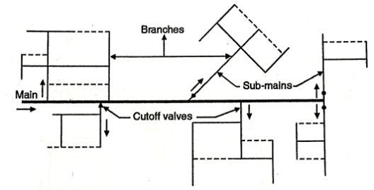
- This system is general used for the unplanned, old towns or cities where there is no given pattern of roads.

Fig: Dead end system
Advantages of Dead-end System:
- The cost of construction is low.
- As the number of valves are less the determination of pressures and discharges is easy.
Disadvantages of Dead-end System:
- As it is a distribution system developed for an unplanned settlement, they are 10% of dead-ends which create the stagnation of water.
2. Grid-Iron System:
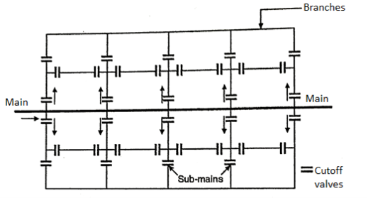
- This method is useful for a settlement which has a rectangular layout. In this system the water mains and the branches are laid in the same rectangular manner.
- This is an improved system of distribution as there are no dead ends and so no chance of stagnation of water.
- All the ends are connected to the mains.

Fig: Grid-Iron system
Advantages of Grid-Iron System:
- As there are no dead-ends, the water is kept in good circulation.
- If there is any kind of breakdown in the supply of water, the water can be made available from some other direction.
Disadvantages of Grid-Iron System:
- It is difficult to calculate the exact size of the pipe as there is provision of valves on all the branches.
3. Circular or Ring System

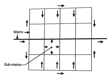
Fig: Circular method
- This system also is useful for a settlement which is planned. In this supply of main is laid all along the peripheral roads and the sub-mains branch out from the mains.
- This system is like the Grid-Iran system, where the flow pattern is same, with no dead-ends.
Advantages of Circular System
- Determination of the size of the pipe is easy.
- The water can be supplied to any point at least from two directions.
4. Radial System:

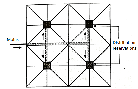
Fig: Radial system
- In this system the total area is divided into different zones.
- The water is pumped into the distribution reservoir, which is kept at the centre of each zone.
- The supply pipes from the reservoir are laid radially, which end at the periphery of each zone.
Advantages of Radial System
- It makes a quick supply of water to each house in all the zones.
- Calculation of the size of the pipe is easy.
- The development of zones help to have enough and regular water supply to each zone.
- These zones are based on Density of population, Type of locality and The Relief of the region. Each zone having the difference in elevation by 15 to 25 m is served by separate system.
- The layout should be such that the difference in pressure between different areas of the same zone should not exceed 3 to 5 m.
Pressure in the Distribution System
- The water starts losing head as it starts flowing through the piper, bend valves and other types of fittings, mainly due to the friction. It is necessary to have an effective head available at the service connection of any consumer to make the water rise upto the top floor of the building.
- The pressure required at a particular point in a distribution system depends upon the following factors.
- The height of the tallest building in that area.
- The distance of the service connection from the service reservoir.
- The pressure required to be maintained near the fire hydrant.
- The provision of meter. [The head loss is maximum when the water flows through the water meters].
- Availability of funds i.e. If the higher pressure is required at the consumer's end. The height of the distribution reservoir is required to be increased which needs higher cost.
Pressure requirement for the residential areas:
- Upto 3 storeys: 2 kg/cm²
- 3 to 6 storeys: 2 to 4 kg/cm²
- 6 to 10 storeys: 4 to 5.5 kg/cm²
- More than to storeys: 5.5 to 7 kg/cm²
At fire fighting Nozzle, the required pressure is 5 kg/cm².
The water distribution systems are of three types such as:
- Gravitational System
- Direct Pumping
- Combined System
1.Gravitational System
- In this the water flows from the source region to the treatment plant and from the treatment plant to the distribution centre, by gravity, by taking the advantage of the sloping of the terrain, it is a reliable and low cost system.
2.Direct Pumping
- In this, the water is pumped from the source to the treatment plant and from the treatment plant to the distribution centre.
3.Combined System
- In this both the gravity and the pumping methods are combined, wherever required.
- Among these three methods of water supply the gravitational system is cheap but it is difficult to maintain the water pressure.
- In the direct pumping system the pressure and quantity of water can be maintained but it is costly, it fails when the power supply (electricity) fails.
- The water pressure has a lot of fluctuation at the consumes end. So if both the systems are put together, the combined water supply scheme gets the advantages which are as follows:
- The pumps can work at a given convenient schedule.
- The required pressure can be maintained during the water supply.
- When the power fails, the advantage of gravity flow can be taken for the water supply.
- The quality of water improves due to the period of detention, in the elevated reservoir.
Key Takeaways:
The beginning of the water distribution system is the end of the water treatment plant. After the purification of water it is supplied through the pipe lines to the individual houses, industrial units and to the public places with a given pressure and in a given required quantities.
Storage Reservoir:
- The pool of water created via way of means of the development of a dam throughout a river is referred to as reservoir. When the reservoir stays in water deliver in the course of the wet season and releases it in the course of dry length as in step with requirement, it's miles referred to as garage or impounded reservoir.
- The garage reservoir is normally built at the notion – a perennial river which can't deliver water in the course of the summer time with the garage reservoir, the float of water withinside the river is regulated.
- The diverse functions for which the garage works are required are
- Irrigation
- Hydro-electric powered energy generation
- Domestic and business water deliver
- Control of detrimental floods
- Low water law for generation
- Recreation
- Preservation and breeding of beneficial aquatic life
- The reservoirs which serve one a couple of motive are called unmarried or multi-motive reservoirs respectively.
Distribution Reservoir:
Distribution reservoirs, additionally referred to as provider reservoirs, are the garage reservoirs, which shop the handled water for offering water throughout emergencies (consisting of throughout fires, repairs, etc.) and additionally to assist in soaking up the hourly fluctuations withinside the ordinary water demand.
Functions of Distribution Reservoirs:
- To soak up the hourly versions in demand.
- To preserve consistent stress withinside the distribution mains.
- Water saved may be provided throughout emergencies.
Location and Height of Distribution Reservoirs:
- Must be positioned as near as feasible to the middle of demand.
- Water stage withinside the reservoir ought to be at a enough elevation to allow gravity go with the drift at an good enough stress.
Depending upon the format of numerous pipes of a distribution gadget there are 4 special structures of format of distribution gadget as indicated below:
1. Dead-End System or Tree System:
- In this gadget, one principal pipe line runs via the centre of the place to be served, and from each aspects of the principle pipe line sub-mains take off. The sub-mains divide into numerous department traces from which carrier connections are given to the customers.
- Thus the complete distribution place is blanketed through a net-paintings of pipe traces walking like branches of a tree. There aren't anyt any pass connections among special sub-mains and branches, and subsequently there are some of lifeless leads to this gadget. Due to numerous lifeless ends, there may be accumulation of sediment there and stagnation of water.
- The lifeless-give up gadget of format is followed in cities or towns that have evolved in a haphazard way with out right making plans. The water deliver mains are laid at random with none making plans of destiny roads.
- The numerous blessings of lifeless-give up gadget of format are as follows:
- In this situation the release and strain at any factor withinside the distribution gadget may be labored out appropriately and subsequently the layout calculations are easy and easy.
- The pipe diameters are to be designed for the populace in all likelihood to be served through them handiest. This may also make the gadget reasonably-priced and economical.
- In this gadget of format relatively much less range of cutoff valves are required.
- The laying of pipes is easy.
- The numerous hazards of lifeless-give up gadget of format are as follows:
- In the case of harm or restore in any phase of the gadget, the water deliver to the complete component past that factor can be absolutely cut-off. Thus big part of the distribution place can be affected ensuing in superb inconvenience to the customers of that place.
- There are range of lifeless-ends withinside the gadget because of which unfastened circulate of water is avoided and stagnation of water results. This stagnation of water may also result in degradation in its quality. Further there can be accumulation of sediment on the lifeless ends.
- As such a good way to take away this stale water in addition to the deposited sediment, scour valves are furnished on the lifeless ends. However, this degree is expensive due to the fact except the fee of scour valves, big amount of dealt with water is thrown to waste and additionally cautious attendance and operation of scour valves is required.
- The gadget is much less a success in retaining high-quality pressures withinside the faraway parts.
- In this gadget given that water provided to any place is received from the principle pipe line at one factor handiest, the water to be had for firefighting can be limited. Further on this gadget it isn't always viable to growth the materials through diverting from every other side.
2. Grid-Iron System or Reticulation System or Interlaced System:
- In this gadget of format the mains, sub-mains, and branches are interconnected with every different. The principal pipe line runs via the centre of the place to be served and from each aspects of the principle pipe line sub-mains take off in perpendicular directions.
- The department traces interconnect all of the sub-mains. Thus in this situation water may be made to flow into via the complete distribution gadget. This gadget of format is greater appropriate for towns laid out on a square plan comparable to a grid-iron.
- The numerous blessings of grid-iron gadget of format are as follows:
- There is unfastened circulate of water, with none stagnation or sediment deposit. Thus probabilities of pollutants of water because of stagnation aren't there.
- Due to interconnection water is added at each factor of distribution gadget with minimal lack of head.
- In the case of harm or restore in any phase of the gadget, the water deliver to handiest very small place of the distribution gadget is affected.
- When hearthplace occurs, lots of water may be made to be had for firefighting reason through manipulating the cutoff valves and diverting the materials from different sections.
- The numerous hazards of grid-iron gadget of format are as follows:
- In this gadget of format a big range of cutoff valves are required.
- This gadget of format calls for longer lengths of pipes.
- The technique for calculating the sizes of pipes and for operating out pressures at numerous factors withinside the distribution gadget is laborious, complex and difficult.
- In this gadget of format the fee of laying distribution pipes is greater.
3. Circular System or Ring System:
- In this gadget of format the principle pipe line is laid to shape a closed ring, both round or square, across the place to be served.
- The complete distribution place is split into small round or square blocks and the principle pipe traces are laid at the outer edge of those blocks. The sub-mains take off from the principle pipe traces and run at the indoors of the place. Thus in this situation water may be provided to any factor from as a minimum directions. This gadget of format is maximum appropriate for towns having properly deliberate streets and roads.
- Further this gadget of format possesses the equal blessings and downsides as the ones of grid-iron gadget of format. However, withinside the case of round gadget of format the period of the principle pipe line is a great deal large and additionally big amount of water may be made to be had for firefighting.
4. Radial System:
- This gadget of format is simply the opposite of the round or ring gadget of format, with water flowing in the direction of the outer outer edge in preference to from it. In this gadget the complete distribution place is split into some of small distribution zones and withinside the centre of every quarter a distribution reservoir is furnished.
- Water received from the principle pipe line is pumped into the distribution reservoir from wherein it's far provided via radially laid distribution pipes walking in the direction of the outer edge of the distribution quarter. This gadget of format guarantees excessive strain in distribution and it offers short and green water distribution. The calculations for layout of pipe sizes also are easy. The radial gadget of format is maximum appropriate for towns having roads laid out radially.
- It may also, however, be said that typically handiest someone of those 4 structures of format might not be appropriate for the complete town or city. In real exercise for any town or city relying upon the different factors which include relative stages of various zones of the town or city, format of its roads and streets, etc., a aggregate of or greater of those 4 structures of format can be greater appropriate and the equal may also consequently be followed.
The diverse steps worried withinside the layout of a distribution device are as indicated beneath:
1. Survey and Preparation of Contoured Plans and Maps:
- The strip of land mendacity among the remedy plant (water works) and the distribution vicinity is surveyed to reap ranges for solving the alignment of the primary pipe line so as to deliver dealt with water to the distribution vicinity. The distribution vicinity (town or town) is likewise absolutely surveyed and contoured plan of the vicinity is ready to discover the positions of the distribution zones, distribution or carrier reservoirs, pumping stations, etc.
- Further specific maps of the distribution vicinity are organized to reveal the positions of roads, streets, lanes, business locality, business vicinity, parks and gardens, etc. The cross- sections of the roads, streets, lanes, etc., also are organized displaying the positions of the prevailing underground carrier strains which includes electric powered strains, phone strains, fueloline strains, sewer strains, current water deliver strains, if any, etc.
2. Tentative Layout:
- The whole distribution vicinity (town or town) is split into diverse distribution zones and the identical are marked at the specific map of the distribution vicinity.
- The density of populace (i.e., common quantity of men and women in step with hectare vicinity) for every area is likewise marked.
- The device of format to be followed is determined and tentative alignment of all mains, sub-mains and branches in addition to positions of distribution or carrier reservoirs, valves, hydrants and different appurtenances are marked.
3. Discharge in Pipe Lines:
- The discharge preferred to be carried with the aid of using every pipe line is computed on the premise of density of populace, kind of distribution area (i.e., residential, business, etc.) and hearthplace demand. The length of the distribution pipes are so constant that the minimal residual strain is maintained in any respect points.
- The pipes are designed for a discharge starting from 2.25 to three instances the common price of deliver. For populace over 50,000 the distribution mains are designed for a discharge of 2.25 instances the common price of deliver, even as for populace beneath 50,000 the distribution mains are designed for a discharge of three instances the common price of deliver.
4. Calculation of Pipe Diameters:
- For the acknowledged layout discharge the pipe diameters are assumed in this sort of manner that the speed of waft varies from 0.6 to three m/s. Smaller speed is thought for pipes of smaller diameter and large speed for pipes of large diameter.
- The lack of head withinside the pipes is then calculated the use of Hazen-Williams method or Darcy-Weisbach method or Manning’s method. Out of those formulae Hazen-Williams method is extra normally used. The use of Hazen-Williams method, however, includes trial mistakess solution, and with a purpose to keep away from this a nomogram of Hazen-Williams method has been developed.
- There are in all 4 variables:
- Discharge Q in m3/s or litres/s second;
- Diameter of pipe in mm,
- Loss of head in metres in step with a thousand m period of pipe, and
- Velocity of waft in m/s.
- If out of the 4 portions, any are acknowledged, the alternative may be discovered from the nomogram.
- For this a immediately facet is located at the values of the 2 acknowledged portions, and the values of the 2 unknown portions are then at once examine out.
- The nomogram is legitimate for a price of roughness coefficient CH same to 100. For another price of CH the pinnacle loss acquired from the nomogram is expanded with the aid of using the thing CH /100.
5. Computation of Available Residual Pressure Heads:
- Starting from the distribution or carrier reservoir, or the pumping station wherein the full strain head is acknowledged, the strain head to be had on the stop of any pipe line can be decided with the aid of using making an allowance for the frictional lack of head and any upward thrust or fall because of slope of the pipe line and the floor ranges.
- If the to be had residual strain head is much less than the specified minimal residual strain head then the assumed pipe length must be revised.
References:
- G.B Masters, Introduction to Environmental Engineering and Science, Pearson Education,2013
- M.Chandrasekhar, Environmental science, Hi Tech Publishers,2009
- Gerard Kiely, Environmental Engineering, McGraw Hill Education Pvt.Ltd, Special Indian Edition, 2007