Unit - 2
Soil Hydraulics
- Consider a rigid cylindrical mould or container as shown in Fig. The dry sand is filled in this rigid cylindrical mould. It is assumed that there is no side friction in the cylindrical container or mould.
- Surface of the soil is subjected to load Q through a piston and this load is transferred to the dry soil grains filled in the container through their points of contact. The average stress at any section x-x can be determined as follows
 av =
av =
Where,  av =Average stress; A= sectional area of the cylinder
Any plane like x-x do not pass through all the points of contact, but many of the grains are cut by the plane x-x and the actual points of contacts seems like a wavy form.
The average stress which is responsible for the deformation of the soil mass is called as effective stress or intergranular stress see Fig. For better understanding. Note that o, o is the effective stress.
- In another experiment, cylindrical mould is filled with the fully saturated soil and cylindrical mould is entirely made water tight. If the same load (Q) is placed on the piston, the load will not be transmitted to the soil grains but in case of Fig. The same load was transmitted to the soil grains (dry).
- Pore Pressure: The pressure which is developed in the water due to external load transmitted to the water in the pore by assuming water to be incompressible is called as pore pressure or neutral stress (uw) which is shown in Fig.

Fig 1: Specimen
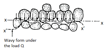
Fig 2: Intergranular pressure
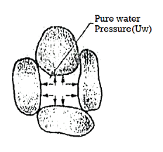
Fig 3: Pore water pressure

Fig 4: The effective stress principle
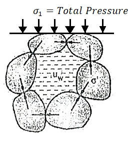
Fig 5: The effective stress principle
uw = neutral stress=Q/A
Where, Q=load applied by piston
A=sectional area of the cylinder
Uw =pore pressure or neutral stress
- In Fig., as soon as valve V is opened, there will be immediately, expulsion of water through the hole and this flow continues for some time and then stops. Note that expulsion of water from the pores decreases the pore water pressure, but increases the intergranular pressure. Hence at any stage; the total pressure split up between water and the points of contact of grains which make a new equation as follows:
Total pressure ( ) =
) =  + uw
+ uw
Where,  =Intergranular pressure
Uw =pore water pressure or neutral stress.
For no expulsion of water, uw = 0,
Hence total pressure ( )= Intergranular pressure (
 )
)
Fig. Shows the concept of total pressure, intergranular pressure and pore water pressure.
 =
= is called as effective stress equation where
  =effective stress,
  t=total pressure and uw= porewater pressure.
Key Takeaways:
The pressure which is developed in the water due to external load transmitted to the water in the pore by assuming water to be incompressible is called as pore pressure or neutral stress.
- Definition: Permeability is defined as "The property of a porous material which permits the passage or seepage of water (or other fluids) through its interconnecting voids".
- If water flow easily through voids of soil, then soil is highly pervious or permeable and when the permeability is extremely low it is called impervious or impermeable.
Coefficient of Permeability:
- Definition: The coefficient of permeability (K) is "The average velocity of flow that will occur through the total cross-sectional area of soil under unit hydraulic gradient" and unit is cm/sec, m/day, feet/day
- According to USBR soil having the coefficient of permeability greater than 10 mm/sec such soils are permeable soils.
- Soils having values less than 10 mm/sec are impermeable soils.
- The soils which have in between values are semi-permeable soils.
Key Takeaways:
Permeability is defined as "The property of a porous material which permits the passage or seepage of water (or other fluids) through its interconnecting voids".
Factors affecting permeability:
Permeability depends on many factors. Following are the main factors that affect permeability:
Grain size:
- Grain size of the soil, or the effective size Dio is one of the factors which affect permeability. Allen Hazen gave the relation.
K = C(D10)2
Where, K Coefficient of permeability in cm/s and D10 is the effective grain size of the soil, C= constant (between 100 to 150)
- The permeability of coarse-grained soil is more than that of fine-grained soil
Properties of pore fluid:
- Permeability is directly proportional to the unit weight of pore fluid and inversely proportional to the viscosity of the pore fluid.
Temperature:
- Since viscosity of the pore fluid decreases with the temperature, permeability increases with temperature, as unit weight of the pore fluid does not change much with change in temperature.
Void ratio:
- Increase in void ratio increases the area available for flow, hence the permeability increases for critical conditions.
K e2
e2
Stratification of soil:
- Stratified soils are those, which are formed by layer upon layer of earth or dust deposited upon one another.
- If the flow is parallel to the layers or stratification, the permeability is maximum while the flow in perpendicular direction to the stratification occurs with minimum permeability.
Entrapped air and organic impurities:
- Organic impurities and entrapped air obstruct the flow and coefficient of permeability is reduced due to their presence.
Adsorbed water:
- Adsorbed water means a thin, microscopic film of water surrounding individual soil grains.
- This water is not free to move and hence reduces the effective pore space and thus decreases the coefficient of permeability.
Degree of saturation:
- The permeability of partially saturated soil is less than that of fully saturated soil.
Shape of particles:
- Permeability is inversely proportional to the specific surface e.g., the angular particles have more specific surface as compare to rounded particles. Therefore, the soil having angular particles is less permeable than soil of rounded particles.
Structure of soil mass:
- For same void ratio the permeability is more for flocculant structure as compare dispended structure.
Key Takeaways:
Factors affecting permeability are as follows:
- Grain size
- Properties of pore fluid
- Temperature
- Void ratio
- Stratification of soil
- Entrapped air and organic impurities
Laboratory measurement of permeability:
Constant head method as per IS2720:
- It is based on measuring the volume of water flowing through a soil sample of known cross sectional area A and length L in time t under a constant head h of water.
- The arrangement is shown in Fig.

Fig 6: Constant head permeability test
- The soil sample is enclosed in a perspex cylindrical tube. A number of manometer points are provided of the side of the cylinder. These can be used in pairs.
- One such pair is shown in the figure.
- Water is allowed to flow through the soil at a constant head 'h' as indicated by the level difference in manometer tubes.
- The quantity of water or volume of water V collected in time t is measured, from which discharge q is calculated. The coefficient of permeability is then calculated as,
K= =
=
Where q=v/t=discharge in m3/s
V=volume of water collected in m3 in time t sec
A=cross sectional area of specimen in m
h =level difference between the manometer tubes in m.
L =distance between manometer points in m
- Vacuum is used at the start of the test to ensure that all entrapped air from soil sample is removed keeping valves A and B closed.
- Then the valve C is closed. Valve A is used to control the flow so that a constant head flow is achieved as indicated by constant level difference 'h' between the manometer tubes.
- This test can be used for highly pervious soils where falling head test cannot be used due to very rapid fall in head, which cannot be measured.
- This test cannot be used for soil with very little permeability or highly impervious soils like clay as rate of collection of water may be very low, sometimes even days, so that the rate of evaporation may be higher.
- This will give wrong results as much of the volume of collected water will evaporate.
Key Takeaways:
Constant head method is based on measuring the volume of water flowing through a soil sample of known cross sectional area A and length L in time t under a constant head h of water.
Falling Head Method as per IS 2720:
- This test is used to determine the permeability of fine-grained soils with very low permeability.
- Due to low permeability, the collected water will evaporate and will lead to wrong results in constant head test. Hence, this: test is used.
- The arrangement is shown in Fig.

Fig 7: Falling head permeability test
- A cylinder containing the soil sample is placed on a base, i.e., a perforated disc, fitted with a fine gauze. The cylinder has a rubber stopper at top in which a graduated stand pipe is fitted.
- The test is conducted by filling the standpipe with de-aired water. It is allowed to flow through the soil sample.
- During the test, the water level in the stand pipe continuously drops and the height of the water in stand pipe is measured at several time intervals and it is then recorded. Any one pair of measurements can be used to calculate the coefficient of permeability from the following formula:
K = 
Where, a =area of c/s of stand pipe.
A =area of soil sample.
L = length of soil specimen
And h1, h2=heights of water measured in the stand pipe at time t1 and t2
If t2-t1 then
K = 2.3
- Several pairs of readings are used in this way and average of 4-5 values gives the average coefficient of permeability.
Key Takeaways:
This test is used to determine the permeability of fine-grained soils with very low permeability. Due to low permeability, the collected water will evaporate and will lead to wrong results in constant head test. Hence, this: test is used.
Field test for determination of permeability:
Pumping in test as per IS5529 Part-1:
- In pumping in test, an individual strata through which hole is drilled, is considered so as to find the value of 'K’.
- Advantage pumping-in-test over the pumping out test:
- Pumping-in-test is more economic than pumping out test.
- It gives more reliable values than pumping-out-test.
- It gives the value of 'K' of strata very close to the hole but pumping-out-test gives the value of K for large area surrounded by the hole.
Generally, there are the types of pumping-in-test
- Open end test
- Packer test
Types of pumping-in-tests:
- Open-end test
- Packer tests:
a. Single packer test
b. Double packer test
1. Open-end test:
- In open-end test, a pipe casing is inserted into the hole of bore up to the required depth and then pipe casing is entirely cleaned out.
- Fig. Show the open-end test.

Fig 8: Open end test (constant discharge)
- At the time of cleaning, the hole is kept under water if it extends below the level of water table, which prevents the possibility of squeezing of the soil into the bottom of the pipe casing at the time of removing i the driving tool.
- After cleaning the hole, hole is filled with water by a metering system. When the steady conditions are developed, that time the constant rate of flow or discharge (q) is found
- The coefficient of permeability is then found by the following expression.
K =
Where, K = coefficient of permeability
H = difference of level between the inlet of casing and water table
q = discharge
r= inner radius of pipe casing
- As per the requirements, the discharge 'q' can be increased by pumping-in water under pressure 'p' as shown in Fig. 2.6.6 and then the value of H becomes equal to (H+
 )
) - Note that for better results, the lower end of the pipe must be at a distance not less than 10r from the top and bottom of the strata.
- The open-end test can also carried out above W.T i.e., water table as shown in Fig.
- When this test is carried out above water table, it is very difficult to make up the constant water level in pipe casing and hence some surging of this vel has to be tolerated.
- (k=
 can also used in this case, However, H is equal to the difference of inlet level and the bottom end of the pipe.
 - As per the requirement, discharge can be increased by pumping in water under a pressure 'p' and that time total head becomes equal to (H+
 )
)
2. Packer test:
- The packer tests are carried out in an uncased portion of the pipe casing and it is commonly used for testing the rocks and sometime used for testing of soil provided the bore hole is open without any casing.
- There is the type of packer tests
(a)Single-packer tests
(b) Double-packer tests.
(a)Single-packer tests:
- This test is carried out under the situation when the hole cannot stand without a casing The packer is located as shown in Fig.
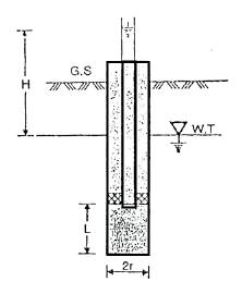
Fig 9: Single packer test (hole tested below W.T)
- Water is pumped into the hole then it comes out of the sides of uncased. Portion of the hole below the packer. For fel depth of casing: stratum should have perforations in its portions for testing. Lower end of the casing is closed by plug.
- Discharge 'q' found at steady condition. The value of K is determined by the following expressions. If L2 10r, then
K=
If 10r > L >r, then
K =
Where, K =coefficient of permeability
H = difference of water level at the entrance and the ground water table for the hole tested below W.T i.e., water table
r = inner radius of hole
 =are hyperbolic sine
- In Fig., if the hole is taken above the W.T i.e., water table for testing a H becomes equal to the difference of levels of water of the entry and middle of the test position.
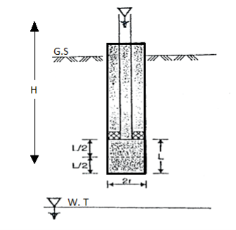
Fig 10: Single packer test (hole tested above W.T)
- In case of open-end tests, the value of H becomes equal to (H+
 )
) - Packer is removed after the completion of test. If again test to be performed, this hole is made deeper and a packer is placed.
(b)Double-packer-test:
- This test is performed under the situation that if the hole can stand without provision of casing.
- In this test, the hole is drilled to the final depth and then filed with water, surged as hailed out.
- Double-packer or two packers are used in this test and these two packers are fixed in the pipe as shown in Fig.
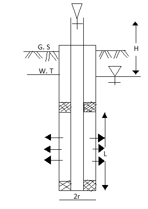
Fig 11: Double packer test (test section below W.T)
- The bottom of the pipe fixed with packers is closed by plug.
- In Fig. The section is below the water table (W.T) and in fig. The test section is above water table (W.T)
- The value of coefficient of permeability is determined by using following equations
- If L > 10r, then
K=
Or if 10r > L > r, then
K=
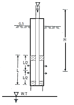
Fig 12: Double Packer test (test section above W.T)
Key Takeaways:
Types of pumping-in-tests are as follows:
1.Open-end test
2. Packer tests: Single packer test, Double packer test
Pumping out test as per IS 5529 Part1:
- For determination of coefficient of permeability, the laboratory tests like constant head permeability and fall head permeability do not give the most accurate and correct results. The samples used in test are mostly disturbed and do not represents the true in-situ structure. Hence for getting good and correct results, the field tests are being carried out.
- In this test, the water is pumped out from the wells which is especially drilled for this purpose. This test is generally used in practice so as to measure the coefficient of permeability of soil for large engineering projects. For homogenous deposits and coarse-grained deposits this method is more suitable and useful because it is difficult to obtain undisturbed samples for this kind of deposits. This test is more expensive and hence used for bigger engineering projects.
- Ground water occurs in previous deposits known as aquifers which can be easily pumped out.
Unconfined aquifer
- If an aquifer does not have an aquiclude al top and the water table is in the aquifer itself, then it is called as unconfined aquifer.
Confined aquifer
- If the aquifer is confined between the aquicludes, one at its top and the other at its bottom them it is called as confined aquifer.
- The value of K i.e., coefficient of permeability of the soil can be determined by using equations for confined aquifer and unconfined aquifer separately.
(a) To find coefficient of permeability 'K' by using equations for unconfined aquifer:
- A tube well is drilled in case of unconfined aquifer till it reaches the underlying impervious strata.
- Perforated tube is used for the well so as the allow the water to enter in the well.
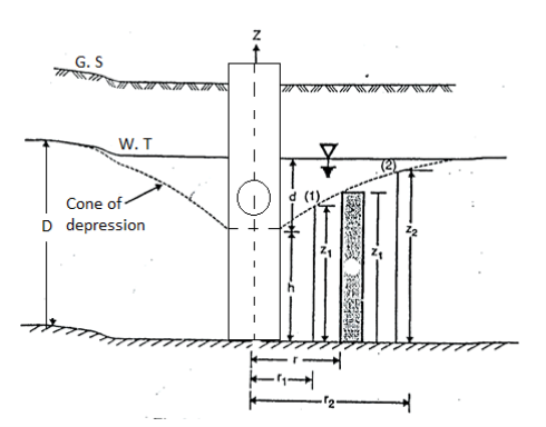
Fig 13:’K’ unconfined aquifer
- The complete tube is surrounded by strainer (screen) so as the identity the flow of soil particles into the well, water from the well is pumped out of the tube till a steady state is obtained. At the steady state, the discharge (4) becomes constant and water level in the tube remains unchanged. Because of pumping, the water near the well forms an inverted cone termed as the cone of depression and maximum depression of the water table is termed as draw-down (d),
Dupuit's Assumptions:
Derivation of 'K' can be obtained by following Dupuit's assumptions.
- Darcy's law is valid and flow is assumed to be laminar.
- Soil material is homogeneous as isotropic i.e., having equal elastic properties in all directions.
- The flow is assumed to be steady.
- The well penetrates the whole thickness of aquifer.
- Coefficient of permeability is assumed to be constant.
- The flow of water towards the well is horizontal and radial.
- The slope of the hydraulic gradient (i) line is small
i = 
8. Consider a flow through a cylindrical surface having height 'h' and at a radius distance 'r' from the centre of well.
q= KiA
K =coefficient of permeability
i = hydraulic gradient= dz/dr
A = total cross-sectional area of soil = 2 rz
rz
q=K )
) (2
(2
 =
= zdz
zdz
Integrating the above expression (2.9.1) for observation well I and 2, we get
 =
=
 k =
k = 
- Note that, there is a rapid drop in head near to the test well. Slope of the hydraulic gradient is steep hence, the assumption '7' is not satisfied.
- Wells I and2 should be drilled at considerable distance for observation so as to obtain accurate measurements. Rl is radial distance of the well should be at least equal to the thickness of aquifer having depth 'D'.
- The radius of influence varies between 150 m to 300m
- By Sichardt, R can be obtained as
R = 3000d √K
Where, R = radius of influence in m
K = coefficient of permeability 'm'/sec.
d=drawdown in 'm'
- By Kozeny, R can be obtained as
R = { )(
)( )1/2}1/2
Where, t= time required to establish steady conditions
n = porosity
- Equations (ii), can be written as
K =
Where, rw= radius of test well
R= radius of influence
D =depth of aquifer measured below the water table
h =depth of water in the well
Equation (iii) gives an approximate value of 'K' i.e., coefficient of permeability because the following reasons:
- Slope water surface near the well is steep.
- Dupuit's assumption is justified.
- Value of radius of influence (R) is approximate.
(b)To find 'K' by using equation for confined aquifer
- Let b thickness in confined aquifer lying between the two aquicludes. The water pressure is shown by the piezometric surface which is the above the top of the aquifer in confined aquifer. Note that piezometric surface and water table level is same for a confined aquifer.
- The piezometric surface (P.S) is horizontal in the beginning and once the pumping is started from the well, piezometric surface is depressed and finally a cone of depression is formed.
- Note that assumption which are used in case of unconfined aquifer are also used in case of confined aquifer for the purposed of derivation to find 'K’.

Fig 14:’K’ by confined aquifer
Let q discharge through cylindrical surface at a radial distance 'r' from the centre and z= height.
q=KiA ...by Darcy's law
q=K ( )(2
)(2 …...∴i=dz/dr and A=2
 rb
rb
 =
= (dz)
(dz)
Integrating the above equation, we get
∴K= 
Key Takeaways:
In this test, the water is pumped out from the wells which is especially drilled for this purpose. This test is generally used in practice so as to measure the coefficient of permeability of soil for large engineering projects.
- In 1856 Darcy studied and demonstrated experimentally, the velocity of laminar flow through homogeneous soil mass, which states that, "The rate of flow or the discharge per unit time is proportional to the hydraulic gradient."
q= K.i.A
V=q/A
V i, V=Ki
Where,
q= discharge per unit time
A= total c/s area of soil mass, perpendicular to the direction of flow
i =hydraulic gradient K Darcy's coefficient of permeability
v =velocity of flow, or average discharge velocity
- If a soil sample of length 1 and cross-sectional area A, is subjected differential head of water hA-hB, the hydraulic gradient i will be equal to (hA-hB)/L and
We have,
q=KA (hA-hB)/L
When hydraulic gradient i = 1, then k=v
Key Takeaways:
Darcy’s law states that, "The rate of flow or the discharge per unit time is proportional to the hydraulic gradient."
- Hydraulic Conductivity is the ability of porous medium (i.e., Soil) to transmit water under saturated or nearly saturated conditions.
i =K
Where, i = water flux
K =hydraulic conductivity
 gradient head
- Stratified soils are those, which are formed by lager upon lager of earth or dust deposited upon one another.
- If the flow is parallel to the lagers or stratification, the permeability is maximum while the flow is perpendicular direction to the stratification occurs with minimum permeability shown fig.

Fig 15: Horizontal strata
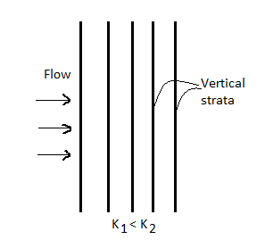
Fig 16: Vertical strata
(1) Average permeability parallel to the bedding planes
- Let L1, L2…Ln be thickness of layer.
- K1, K2…Kn be permeability of layer.
- For flow to be parallel to the bedding planes, the hydraulic gradient i will be the same for all the layers.
- However, since V Ki and K is different, the velocity of flow will different in different layers.
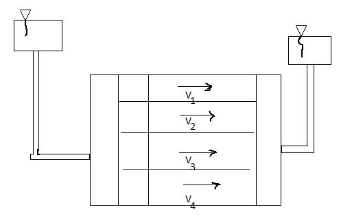
Fig 17: Flow parallel to bedding plane
- Let K= average permeability of the soil deposit parallel to the bedding plane.
- Total discharge through the soil deposit sum of discharge through the individual layers.
q=q1, q2…. Qn
Kx = 
(2) Average permeability perpendicular to the bedding planes
- In this case, the velocity of flow and hence the unit discharge, will be the same through each layer. However, the hydraulic gradient and hence loss through each lager will be different. Denoting the head loss through the lagers by h1,h2….hn, and the total head loss as h we have
h=h1+h2+...hn
But h1=iL1 h2=iL2
h=iL1+iL2+iL3+…
Now, if KZ=average permeability perpendicular to the bedding plane.
We get,
Kz=
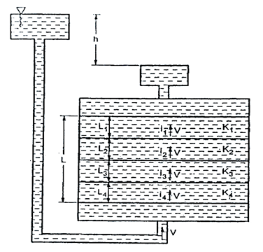
Fig 18: Flow perpendicular to bedding plane
- Hence for same void ratio, the soil with rounded particles are more permeable than with angular particles.
Key Takeaways:
Stratified soils are those, which are formed by lager upon lager of earth or dust deposited upon one another. If the flow is parallel to the lagers or stratification, the permeability is maximum while the flow is perpendicular direction to the stratification occurs with minimum permeability.
- There is an energy transfer between the water and the soil due to the viscous friction exerted on water flowing through the soil pores.
- The pressure exerted by water on the soil through which it percolates is known as seepage pressure (Ps).
It is given by,
Ps=h
Ps =  ×L
×L
Where, h=Hydraulic head,
Z= Length over which the head (h) is lost,
i = Hydraulic gradient,
 =Unit weight of water
Seepage force (F) is given by,
Fs= Ps. A= i.Z. A
A
Where A= Total cross-sectional area of the soil mass
 =Unit weight of water
The seepage pressure always acts in the direction of the flow.
The effective pressure (P) in the soil mass is given by
Pe=Z ± iz
± iz
For upward flow,
Pe=Z - iz
- iz
In upward direction, the effective pressure is decreased hence-ve sign.
For downward flow,
Pe=Z +iz
+iz
In downward direction, the effective pressure is increased hence +ve sign.
Key Takeaways:
The pressure exerted by water on the soil through which it percolates is known as seepage pressure.
- When water flows through Soil in laminar flow conditions, the paths along which the layers of water flow are called flow lines.
- Equipotential lines are the lines joining points of equal pressure along the flow lines. These can also be defined as lines along which the points have equal head of water.
- If piezometers or glass tubes are inserted along an equipotential line, water will rise to the same height in the tubes.
- Equipotential lines are always perpendicular to the flow lines.
- Analysis of seepage phenomenon is simplified by using the graphical solutions. One of the most use graphical tool is "Flow Net".
- The grid, mesh or net formed by the intersection of equipotential lines and flow lines is called flow-net.
- The portion of a flow net between two adjacent flow lines is called a low channel.
- Every section of a flow channel between two successive equipotential line is called a field.
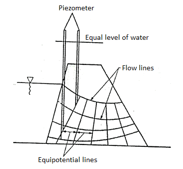
Fig 19: Flow lines and equipotential line
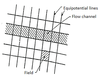
Fig 20: Flow net
Properties of Flow net:
- Following are the characteristic of flow-net, which are useful in construction of flow-nets and in calculation in solving seepage problems:
- In a flow-net, flow lines and equipotential lines intersect each other at right angles.
- The quantity of water flowing through each flow channel is the same.
- The drop of head or potential drop between any two successive equipotential lines is the same.
- The fields are approximately squares.
- The flow net is representative of the flow pattern and dissipation of the hydraulic head see fig below.
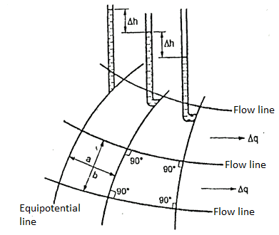
Fig 21: Part of flow net illustrating characteristics
Application of Flow net:
- A flow net chart is used for following purposes:
- Determination of discharge.
- Determination of total head.
- Determination of pressure head.
- Determination of hydraulic gradient.
- For calculating quantity of seepage.
- For stability of earthen dam.
- For analysis of flow phenomenon.
- For stability analysis.
Key Takeaways:
The grid, mesh or net formed by the intersection of equipotential lines and flow lines is called flow-net.
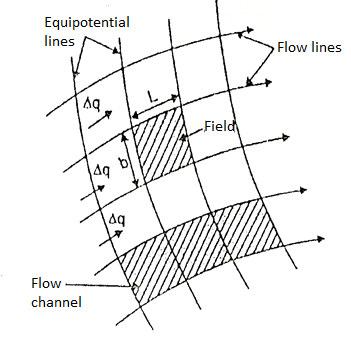
Fig 22: Portion of flow net showing field and flow channels
The portion between two successive flow lines and successive equipotential lines is termed as field.
Let: L= Length of field and b= width of field
 h =Head drop through the field
 q= Discharge through the flow channel
H=Difference between w/s and D/s heads
From Darcy's law of flow through soils, we know,
 q = K.i.A
Consider the unit thickness of the field,


For square field, L=b, we get,

∴ … (1)
… (1)
Let H =Total head loss =h1-h2

Where, Nd= Number of equipotential drops
Substituting in Equation (1), we get,
∴ … (i.e., discharge through one channel)
The total discharge through the complete flow net is given as,
q =
Where, Nf = Number of flow channels
=
∴q =K×H× … (2)
… (2)
Equation (2) gives the seepage discharge.
 is called as shape factor of the flow net.
- ABC is a sheet pile driven in pervious layer of depth d, the depth of embedment BC being d' Fig.
- UB and TV are potential boundaries with known heads. BCST and xy are flow line boundaries because these are impervious surface across which water cannot pass.
- Flow lines will emerge at right angles from UB and end at right angles at TV. Because of symmetry flow not will symmetrical, about vertical axis.
Procedural steps:
- Make a scale drawing showing the structure, soil mass, the pervious boundaries and the impervious boundaries.
- Sketch the first trial flow line as f1 f1 Emerging at right angles at UB running round the sheet pile and meeting TV at right angles.
- Sketch the first equipotential line p1 p1so as to make a square figure with the flow line f1 f1 and the boundary BC and ending at right angles to the boundary flow line, Now sketch the second flow line f2 f2 again emerging at right angles with UB making square figure with P, P, going round the sheet pile parallel to the first line f1 f1 and ending at right angles to TV.
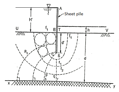
Fig 23: Flow net for sheet pile
4. Then sketch the next trial potential line, emerging at right angles from BC, making square figures with neighboring flow lines and meeting xy at a right angle. Continue sketching to complete the flow net.
5. Now, check (by drawing circles touching all the sides of the square) the square figures and orthogonality everywhere in the flow net. The first attempt can hardly produce a good flow net. Make a second, third and if required more attempts, till a reasonably good flow net has been sketched.
- Figure shows the dam section ABCD has FC as blanket filter and ENJ as top seepage line. BC represents rock line.
Steps:
- Boundaries: EB and FC are potential boundaries and ENJ and BF are bound flow lines.
- Sketch the first trial flow line f1f1 that emerges from EB at right angles, runs keeping the distance from top seepage line and ends at filter boundary at right angle.
- Sketch equipotential lines P₁ P₁ P2 P2. Etc. so that they emerge and meet the boundary flow lines at right angles and form square figures.
- Check the orthogonality and square figures in the figure Pqrs is a non-square if many figures are found to be "non-square" adjust the trial flow line and sketch new equipotential lines. There or more such trial will yield reasonably good net.
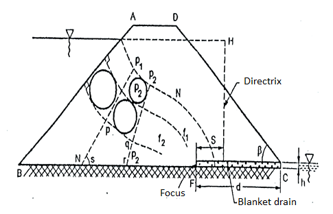
Fig 24: Flow net for earthen dam
- The rain water which falls on the surface of earth percolates through the soil to a level is known as ground water table.
- The minutes pores of soil serve as capillary tubes through which the moisture rise above the ground water table.
- The capillary forces depend upon various factors such as
(a) Surface tension of water
(b) Pressure in water in relation to atmospheric pressure
(c) The size and conformation of soil pores.
- In a water body consider a molecule of water, it is surrounded by other molecules. As force duc to the molecular attraction act all around, the molecule is in equilibrium.
- In case of free surface, the equilibrium of molecule is disturbed as the force exerted by the water molecules below it exceeds that of the air molecules above it. In order to maintain the equilibrium, the surface assumes a curved shape. Thus, surface tension exists at the interface. Surface tension acts in the direction normal to the line drawn on the surface, and is defined as "The force per unit length at that line." As the temperature increases, surface tension decreases.
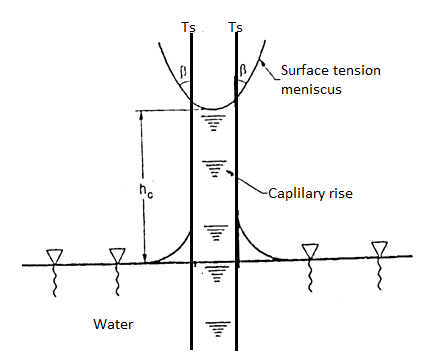
Fig 25: Surface tension and meniscus formation
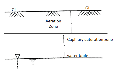
Fig 26: Space above water table
- The interconnected interstices of a soil mass act as capillary tubes of varying diameter. The channels formed in a soil mass are not necessarily vertical and may be inclined in any direction.
- The space above the water table is divided into two regions.
(a) Zone of fully saturated soil which is the capillary saturation zone.
(b) Zone of partially saturated soil which is the aeration zone.
- The height to which the capillary water noses in the soil is known as capillary fringe.
- It includes the zone of saturation and part of the zone of aeration.
- The relation between the maximum height of capillary fringe and the effective diameter is,
(he)max=
Where, C=constant which depend upon the impurity, and the shape of the particle.
e = void ratio
D10= effective diameter in mm
- When flow takes place in an upward direction, the effective pressure gets reduced since the seepage pressure also acts in the upward direction.
- When the seepage pressure becomes exactly equal to the submerged weight of the soil, through which the flow is taking place, the effective pressure becomes zero.
- In this case, the soil with less cohesion loses all its shear strength and soil particles move up in the direction of flow. This lifting of soil particles is known as quick sand condition or boiling sand condition during this condition the effective pressure reduces to zero.
i= ic =
- The hydraulic gradient of the quick sand condition is known as the critical hydraulic Gradient(ic).
- Thus, quick sand condition is the particular flow condition which occurs when effective pressure reduces to zero during upward flow.
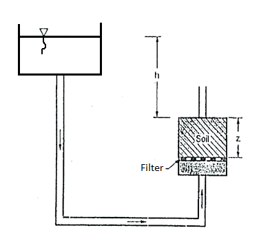
Fig 27: Quick Sand Condition
Key Takeaways:
When the seepage pressure becomes exactly equal to the submerged weight of the soil, through which the flow is taking place, the effective pressure becomes zero. In this case, the soil with less cohesion loses all its shear strength and soil particles move up in the direction of flow. This lifting of soil particles is known as quick sand condition.
- Uplift stress, which is likewise called hydrostatic uplift, is an upward stress implemented to a shape that has the capability to elevate it relative to its surroundings. It is the situation of more pore water stress than the overburden stress of the shape.
- The uplift stress may be difficult if it's miles more than the burden of the shape exerted downwards. ASCE 7-10, states that the upward stress of water will be taken as the entire hydrostatic stress implemented over the whole area. The hydrostatic load will be measured from the bottom of construction.
- The shape has to be designed well to offer more resistance in opposition to uplift forces with a view to save you dangers because of water stress. So, the uplift stress has to be considered throughout layout level considering that rehabilitation and preservation of basis cannot be finished effortlessly withinside the future.
- The opportunity of prevalence of this upward pressure on basis ought to be test while groundwater desk is better than the lowest of the muse level. Due to the reality that hydraulic uplift stress acts in upward direction. Therefore, it reduces the downward weight of the shape and therefore it acts in opposition to the stableness of shape.
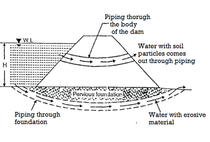
Fig 28: Piping through dam and foundation
Piping through dam
- More than 25% of failures may occurs due to piping due to presence of sand and gravel there may be flow of water causing piping leakage through dam which may lead to failure of dam.
- These may develop due to faulty construction improper compaction. Shrinkage cracks, cracks developed due to settlement of the foundation such effects may be removed by better construction and maintenance.
Piping through foundation
- If soil below foundation is permeable and if foundation strata consist of cavities, then water start seeping through them which may erode the soil causing piping failure.
Sloughing of downstream toe
- It is process in which soil mass falls down after saturation. This may occurs due to saturation of downstream toe. It is a type of local slope failure.
- It occurs when downstream portion of dam becomes saturated and continuously remains in same state causing piping failure.
- It may occur due to choking of downstream drains.
- Fig. Shows piping through dam and foundation to avoid the seepage failures.
Numericals:
Q. The void ratio of a sand sample at the loosest and densest possible states are found to be 0.55 and 0.98 respectively. If G=2.67 determine the corresponding values of the critical hydraulic gradient?
Soln.:
Critical hydraulic gradient Ic=
Critical gradient for loosest state,
e =0.55
∴Ic =
Critical gradient for densest state,
e =0.98
∴Ic =
Q.A Cylindrical mould of diameter 7.5cm contains a 15cm long sample of line sand when water flows through the soil under constant head at a rate of 58cm/min the loss of head between two points 8 cm part is found to be 12.1cm. Determine the coefficient of permeability of the soil.
Soln:
A=
L=15cm
H=8cm
Q=q=58cm3/min
K=
K=2.462cm/min
Q. Determine the coefficient of permeability of soil from the following data:
Length of soil sample=25cm
Area of c/s of the sample=30cm2
Head of water=40cm
Discharge=200ml in 110sec
Soln.:
K =
Q. What is the critical gradient of sand deposit of sp. Gravity=2.65 and porosity 35%.
Soln:
e =0.35
∴Ic=
Q. In order to compute the seepage loss through the foundation of dam, flow net was drawn. The flow net study gave number of flows channel Nf=8 and number of equipotential drop Nd=18.The head of water lost during seepage was 6m if the coefficient of permeability of foundation soil is 4×10^-5 m/min. Compute the seepage loss per meter length of dam per day.
Given:
Number of flow channels Nf=8
Number of potential drops, Nd=18
Head loss=6m
K=4×10^-5 m/min
q =
L=1m
Q=qL=10.67×10^-5×60×24
∴Q=0.154 m3/day
Q. A sample in variable head parameter is 8cm in diameter and 10 cm high. The permeability of the sample is estimated to be 10×10^-4cm/sec. If it is desired that the head in the standpipe should fall from 24 cm to 12cm in 3 min, determine the size of the standpipe which should be used.
Given:
D=diameter of sample=8cm
K=Permeability of sample=10×10^-4cm/sec
Hl =24cm
HL =12cm
t =3minutes=180sec
L=Length of sample=10cm
a =cross sectional area of standpipe
To find the size of standpipe (i.e., d =diameter)
Let d be the diameter of standpipe to be determined
A=cross sectional area of sample=
∴A= d^2
d^2
We know,
K=
10
d =4.079
∴d=4.08cm
References:
- V.N.S Murthy-Soil Mechanics and Foundation Engineering (fifth Edition)
- K.R.Arora-Soil Mechanics and foundation Engineering
- Alam Singh- Modern Geotechnical Engineering
- C.Venkataramaiah-Geotechnical Engineering
- Gopal Ranjan and A.S.R. Rao-Basic and Applied soil mechanics