Unit - 3
Soil Compaction
- This is the simplest method of increasing the performance, characteristics, especially bearing capacity of soil.
- In this method, by the application of force or vibrations, the soil particles are more closely packed thereby increasing the density and hence bearing capacity of the soil.
- Increasing the density of soil by application of mechanical energy is called compaction.
- Compaction is also defined as the process where the density is increased by reducing air voids. It may involve modification of water content or gradation of soil or both.
- The theory of compaction was first developed by R.R. Proctor while building a dam in the USA.
- The principles of compaction developed by him were published in a series of articles in Engineering News record in 1933.
Purpose of Compaction
- Compaction of soil is undertaken for a number of purposes. These are listed below:
- To increase density and thereby shear strength and bearing capacity of soil, this is required in the case of slope stability improvement.
- To decrease the permeability of soil, this is required for earth dams.
- To reduce the settlement of structures after construction.
- To reduce danger of piping, this is required for seepage control of earth dam.
- To increase resistance towards erosion of soil by rain and other causes.
Field Situations Where Compaction is Required:
- As already stated above compaction is required in tl. Following field situations:
- When sufficient bearing capacity is not available even at a greater depth.
- When the soil is totally cohesionless like dry sand.
- When the soil is highly pervious and is used in water retaining structures.
- In economical foundation design.
- In tunnels, roads etc.
- In special soil types.
Key Takeaways:
This is the simplest method of increasing the performance, characteristics, especially bearing capacity of soil. In this method, by the application of force or vibrations, the soil particles are more closely packed thereby increasing the density and hence bearing capacity of the soil.
- The compaction curve is a relationship between the soil water content on X-axis and dry density of soil on Y-axis.
- The relationship between dry density of soil and its water content is as follows:
Ƴd =  where,
Ƴd = dry density of soil
Ƴ = bulk density of soil
w = soil water content
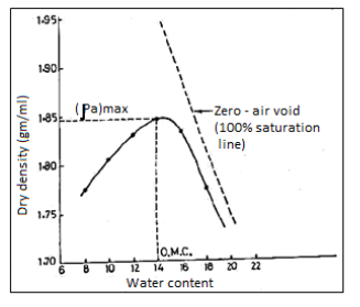
Fig 1: Graph showing relation of water content and dry density
- It has been observed, as can be seen from the curve also, that the dry density initially increases with an increase in water content till maximum density (d)max is obtained. With further increase in the water content, the dry density decreases.
Important Terms related to Compaction Curve:
Optimum Moisture Content or Optimum Water Content: It is the water content corresponding to maximum dry density. Each compactive effort for a given soil has its own OMC, as can also be seen the figure.
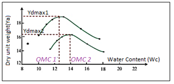
Fig: 2
Zero Air Voids Curve or Saturation Line: For a known water content, theoretical maximum density is obtained when there are no air voids in the soil sample i.e., the soil is 100% saturated. This is depicted by the Zero Air Voids Curve, as shown in the figure.

Fig: 3
Line of Optimums: A line drawn through the peak points of several compaction curves at different compactive efforts for the same soil will be almost parallel to the zero air voids curve, known as the Line of Optimums. Refer to the figure below.
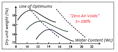
Fig: 4
Key Takeaways:
The relationship between dry density of soil and its water content is as follows:
Ƴd = 
Where,
Ƴd = dry density of soil
Ƴ = bulk density of soil
w = soil water content
- Following factors affect the compaction of soil and the maximum dry density which can be achieved by compaction
- Type of Soil: For the same compactive effort, a well graded coarse grained soil can be compacted to higher MDD than a uniformly graded soil. As the grain size decreases the OMC values goes on increasing and the MDD values goes on decreasing
- Amount of compaction: If the compactive effort is increased, MDD increases and OMC decreases But the increase in MDD is not linear with increase in energy.
- Water content: As is evident, if water content goes on increasing the maximum density of compacted soil goes on increasing upto a certain water content. If water content is further increased, the density goes on decreasing.
- Admixtures: Various admixtures like lime, calcium chloride, aggregates in various proportions etc. are used to improve the compaction properties of soil. Lime can increase the dry density by about 5 to 10%
Key Takeaways:
- Type of Soil
- Amount of compaction
- Water content
- Admixtures
- For rolling, following equipment’s are used
- Smooth wheeled rollers: These have two rear wheels and one large drum in front. The weight is 10 to 16 tons and they are suitable for coarse-grained cohesionless soils.
- Pneumatic / rubber tyred rollers: These have 9 to 11 tyres on two axles in staggered fashion. These are suitable for both cohesive and non-cohesive soil.
- Sheep foot rollers: These rollers have a drum of diameter 0.9 to 1.8 m. This drum has projections of 23 cm length. These projections are called sheep-feet. The contact area of each foot is 35 to 90 cm'. The weight is between 2 to 15 tons. These are suitable only for fine grained cohesive soils Best suited for compaction of the core of an earth dam.
For ramming power rammers are used. These are suitable where access is difficult for rollers.
Vibration equipment consists of vibratory plates of 0.5 to 45 m coverage and 90 kg weight vibrating at 1600 cycles per minute. Vibratory plates are suitable for coarse grained soils with less cohesion.
Field Methods of Compaction:
- Field compaction is carried out by various equipment’s. These equipment’s basically use three different procedures or methods of compaction.
- These methods are: Rolling, tamping or ramming and vibration.
Rolling:
- In this method, rollers of different types pass over the soil and due to their heavy weight, the compaction takes place.
Ramming or Tamping:
- This method is very slow. In this method tampers or rammers are used to give repeated blows to the soil to compact it.
- Watering may be done during ramming.
Vibration:
- In this method the soil is vibrated by equipment known as vibrators.
- Due to vibration, the soil particles are rearranged and more dense packing is possible. This increases the MDD of soil.
Compaction in Laboratory
- Laboratory compaction tests provide the basis for determining the soil compaction needed to achieve the required engineering properties of soil at site. The aim of these tests is to determine the maximum dry unit weight that can be obtained for the given soil sample with a standard amount of compactive effort.
- The proctor test is used to achieve compaction by impact energy. A hammer is dropped several times on a sample of soil kept in a mould. Standard values of the weight of the hammer, height of blows, number of blows, volume of mould etc are given in the IS Codes for different proctor tests.
- According to R.R. Proctor, the compaction of a soil mass depends on the following 4 factors:
- Type of Soil
- Moisture Content
- Compactive Effort
- Dry Density of the Soil
Standard Proctor test:
The stepwise procedure of standard proctor test is given below:
Preparation of specimen:
- Take 16 kg of air-dried sample passing through 20 mm 15 sieve.
- Apply water to bring water content to about 10 percent, less than the estimated optimum water content.
- Keep the soil in an air tight tin for about 20 hours to ensure thorough mixing of the water with the soil.
- Divide the sample in six equal parts.
Compaction test procedure:
- Clean the mould and weigh it to nearest gram.
- Apply grease to inside of mould, base plate and collar.
- Assemble the mould and base plate together on the floor.
- Take one part of sample and fill the mould in 3 layers giving 25 blows to each layer with the 2.6kg hammer dropping from 310 mm.
- Scratch with spatula each layer before putting in the next layer.
- Remove the collar and trim the compacted soil flush with the top of mould with a straight edge.
- Weigh the mould with the soil to nearest gram. Extract the soil from mould with the extruder.
- Cut the soil sample in the middle and take representative sample in an air tight container from middle of the cut surface.
- Determine the water content.
- Calculate bulk density.
- Calculate dry density using bulk density and water content values by using,
 =
=
12. Repeat steps 4 to 11 by taking 2 to 3% more water than preceding test.
13. For all six samples, record the readings and plot moisture content against dry density.
14. Find out dry density corresponding to the maximum point of the curve and corresponding moisture content.
15. This dry density is known as maximum dry density (MDD) and the corresponding water content is known as the optimum moisture content (OMC).
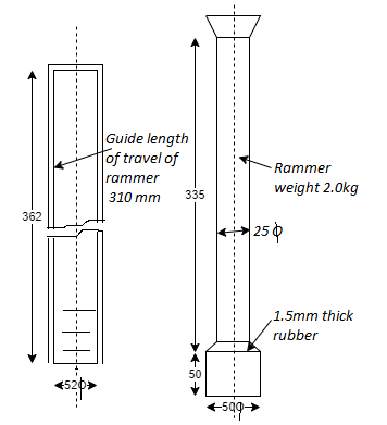
Fig 5: Rammer for light compaction for SPT
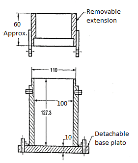
Fig 6: Mould for compaction of SPT
Uses of the Test:
- To obtain OMC and MDD of a given soil sample.
- To get relation between dry density and moisture content for a soil sample.
- To achieve controlled compaction of soil in the field.
Key Takeaways:
- Preparation of specimen
- Compaction test procedure
Modified Proctor Test:
- This Proctor test is used for situations where heavy compaction is indicated.
- The test procedure is almost identical except the three factors, viz: number of layers, weight of hammer and the distance through which the hammer falls. A comparison of standard and modified tests is given below:
Sr no. | Feature | Standard proctor test | Modified proctor test |
1 | Weight of hammer. | 2.6 kg | 4.89 kg |
2 | No. Of layers in which soil is filled in the mould. | 3 | 5 |
3 | Vertical drop of hammer before striking the soil | 310mm | 450mm |
- Mould size in both tests is, 12.73 mm height and 100 mm diameter cylindrical mould and number of blows given in tests is 25.
- Modified Proctor test gives 5 to 10% higher value of dry density and 2 to 3% less OMC as compared to standard test provided that both tests are performed on the same soil.
Key Takeaways:
It is used for situations where heavy compaction is indicated. The test procedure is almost identical except the three factors, viz: number of layers, weight of hammer and the distance through which the hammer falls.
Compaction in Field
Smooth-wheel (or smooth-drum) rollers
- Suitable for proof-rolling of sub-grades and finishing operations of fills with sandy and clayey soils.
- These rollers provide 100% coverage under wheels with ground contact pressure as high as 310-380 KN/m2.
- Not suitable for the application of high weights of compaction when used on thicker layers.
Pneumatic rubber-tired rollers
- Better than smooth-wheel rollers as they have several rows of closed spaced tires (4 to 6 in a row).
- Used for sandy and clayey soil compaction.
- Compaction action consists of combination of pressure and kneading action.
Sheepsfoot rollers
- Consist of drums with large number of projections, with area of each projection ranging from 25-85 cm2.
- Effective in compacting clayey soils.
- Contact pressure ranges from 1400-7000 KN/m2.
Vibratory rollers
- These are extremely efficient in compacting granular soils.
- Vibrators can be attached to smooth-wheel, pneumatic rubber-tired, or sheepsfoot rollers to provide vibratory effect to the soil.
- Vibration effect is produced by rotating off-centre weights.
- The field compaction control consists of the determination of (a) water content at which the soil has been compacted (b) Dry density. For proper compaction control, rapid test methods must be used like calcium carbide method and proctor needle method.
- The proctor needle consists of a needle point attached to graduated needle shank which in turn is attached to a spring loaded plunger. The needle point of varying cross-sectional area is available so that a wide range of penetration resistance can be measured. The penetration force is read on a loaded gauge fixed over the handle.
- To use the needle in the field, a calibration curve is plotted in the laboratory between the penetration resistance as the ordinate and the water content as the abscissa. It is shown in Fig.
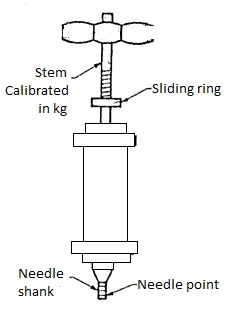
Fig 7: Proctor Needle
- The laboratory penetration resistance is measured by inserting the proctor needle in the compacted soil in the proctor mould. The penetration resistance corresponding to various water contents are thus noted at the end of each proctor compaction, and a calibration curve is plotted.
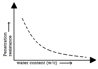
Fig: Water content against penetration resistance curve
- This curve may be used to determine the placement water content. The penetration resistance of the compacted soil in the field is determined with the proctor's nicedic, and its wie is read off from the calibration curve.
- When load is applied on a saturated cohesive soil, initially, entire load is taken by pore water, and later on, due to gradual escape/seepage of water, load is transferred on soil.
- This process of gradual load transfer from pore water to soil Skeleton, and gradual compression is called as consolidation
Primary consolidation settlement (Sc):
- Primary consolidation settlement (Sc) is the settlement resulted due to resistance to flow of water under induced hydraulic gradient.
Secondary consolidation settlement (Ss):
- Secondary consolidation settlement (Ss) is due to plastic deformation of soil at zero excess pore water pressure.
- Mathematically, S= total settlement =S₁=Si + Sc + Ss
- This is shown in curve (b) in Fig. For cohesive soil; which take long time. As against this incase of sandy soil, the entire settlement will not take more time as shown in curve (a) in Fig.
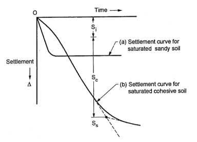
Fig 8: Showing time settlement relation in respect of cohesive and non-cohesive soil
- When compressive load is applied on saturated soil, it will tend to expel water in soil, and thereby cause decrease in volume and settlement.
- If the soil is permeable, water will be expelled quickly, whereas if soil is impermeable, expulsion of water will take time, and settlement will take place gradually.
- Initially, when load is applied, very less load is taken by soil, and the balance load is borne by water called as pore water pressure.
- At any point of time,
Total stress = Stress taken by water + Stress taken by soil
= (Pore water pressure) + (Effective stress)
At time, t=0, effective stress taken by soil = 0
∴Pore water pressure = Total stress
- As time passes, gradually, water is expelled, pore water pressure decreases and effective stress increased.
- When pore water pressure reduces to zero, complete or 100% consolidation is achieved,
And Total stress = Effective stress
- Consolidation is time dependent process and depending upon impermeability of soil, may take long time.
Assumptions in Terzaghi's 1-Dimensional Consolidation Theory
Terzaghi's theory is based on following assumptions
- Compression and flow are one-dimensional (vertical).
- Darcy's law is valid throughout the consolidation process.
- The soil is homogeneous and isotropic.
- The soil is fully saturated.
- The soil grains and water are both incompressible. The consolidation occurs due to expulsion of water from the voids.
- Strains are small; that is, the applied load increment produces virtually no change in thickness, and k and a, remain constant.
- The time lag in consolidation is due entirely to the low permeability of the soil.
- There is a unique relationship, independent of time, between void ratio and effective stress, that is
 e=-a
e=-a ,p, while av is assumed constant over the stress increment.
- The consolidation cell consists of a circular metal ring in which the soil specimen is kept, and it does not allow the horizontal or the lateral movement (deformation) of the soil sample.
- On the top and bottom of the soil sample, porous stones and filter paper are placed to permit two way drainage of water from or into the sample, as desired.
- Axial vertical loads can be applied through the loading machine, on the soil sample. Due to loading, the sample volume decreases, its vertical deformation or compression (lateral deformation prevented) can be measured on a dial gauge attached to the apparatus at top.
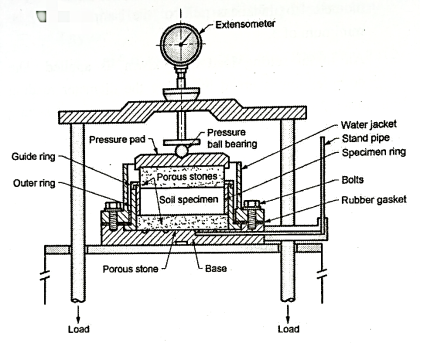
Fig 9: Fixed ring consolidation cell
- In a fixed ring consolidation cell, only the top porous stone is permitted to move downward, as the specimen compresses.
- Direct measurement of permeability of the soil sample at any stage of loading can be made only in the fixed ring consolidation cell, and hence such an arrangement is widely adopted.
- An axial vertical load is applied on soil sample by means of loading yoke.
- The load is transmitted centrally from the loading yoke through a steel ball bearing, which rests on a circular loading plate.
- This provides a uniform pressure distribution on the soil sample.
- A dial gauge, provided near the top end of the machine, measures the compression up to 0.002 mm.
- Near the top end of the soil sample is placed a water jacket, filled with water, around the porous filter stone. This prevents excessive evaporation from the soil sample during the test, and ensures that it remains saturated.
- At the bottom end of the soil sample, the water expelled from the soil flows through the filter stone, and is forced into the stand pipe, which is a sort of a falling or rising head permeameter, and thus helps measuring soil permeability during the progress of consolidation or compression test.
- For performing the test, usually a soil sample of 60 mm diameter is taken. Samples of 50, 70 and 100 mm diameter can also be used in special cases. The diameter to thickness ratio of the sample should be minimum of 3.
- An initial setting load of 5 kN/m² is applied. The compression is noted by taking the diameter reading after 24 hours of the application of the initial setting load.
- Then load increment of say 10 kN/m2 is given and dial gauge readings are taken after 0.25, 1, 2.25, 4, 6.25, 9, 12.25, 16, 20.25, 25, 36, 49, 60 minutes and 1, 2, 4, 8 and 24 hours recorded to indicate the settlement of the sample when the compression virtually ceases.
- After recording the compression readings with time for the first incremental load, the load is increased further by giving further incremental loading, and the test is repeated. Again, load is increased and test repeated, and so on.
- The sequence of the increased loadings (extra to the initial setting load) generally adopted is 10, 20, 40, 80, 160, 320, 640, 800, 1000 kN/m².
- The specimen is unloaded after completion consolidation and is allowed to swell.
- The final dial reading corresponding to the completion of swelling is recorded, and specimen is taken out and dried to determine: (a) its water content; and; (b) mass of the soil solids.
Normally consolidated soil (NC):
- It is one which has never been subjected to an effective pressure greater than the existing overburden pressure and is completely consolidated by the existing overburden.
- NC clays are soft and highly compressible.
- Natural water content of NC soil is closer to liquid limit, wL.
Over consolidation (OC):
- Clay is pre consolidated if it has always been subjected to pressure in excess of its present over burden pressure (in the past).
- A soil may have been pre-consolidated during the geological past by weight of an ice-sheet or glacier which has melted away or by other geologic overburden and structural load which no longer exist now.
- OC clays are relatively less compressible, stiff and hard,
- Natural water content for OC soil is < NC soil, IL = 1 for OC soil.
- It is acquired via way of means of dividing the preconsolidation stress via way of means of the prevailing powerful pressure fee carried out at the soil. The expression for computing the OCR is as given below.
OCR=
- Here, OCR is over consolidation ratio,
 is preconsolidation pressure and
  is powerful overburden pressure.
 - The clayey soil at any intensity in subject could have gone through a height powerful pressure in its loading history. The beyond pressure encountered may be much less, same to or extra than cutting-edge overburden pressure existed all through time of sampling. At this soil sampling period, powerful pressure gift withinside the pattern may lessen and bring about soil expansion.
- When the pattern taken from the sphere undergoes a consolidation test, a small compression will arise ensuing in small extrude in void ratio. It will occur most effective if the whole pressure carried out now could be smaller than the most pressure withinside the soil pattern, gone through withinside the beyond. This type of clayey soil is an over consolidated clay.
- When the whole pressure carried out is greater than the most pressure withinside the subject gone through via way of means of the soil all through the beyond, this type of clayey soil is a usually consolidated clay.
- This most powerful beyond pressure is referred to as preconsolidation pressure. The preconsolidation pressure fee can't be decided because of the versions existed withinside the geological process.
- If the value of OCR is much less than one, then the soil is usually consolidated clay. If the OCR is more than one, then soil is over consolidated.
Following two methods are used to find Cv, the coefficient of consolidation
- Logarithm of time fitting method by Casagrande.
- Square root of time fitting method by Taylor.
Logarithm of time fitting method by Casagrande
- Plot graph of compression of soil by dial gauge reading Vs logarithm of time as shown in Fig.
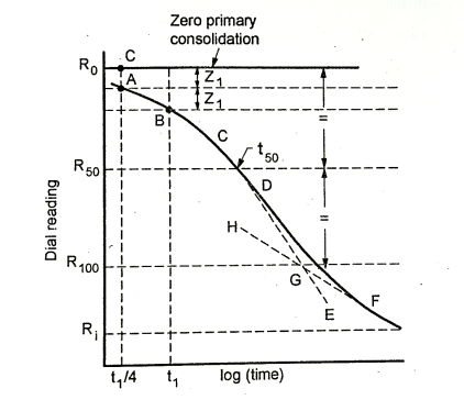
Fig: 10
- Select point A and B on the initial part of the curve, such that time required for point B is four times time required for point A. Let Z1 be vertical the distance between point A and B. Select point C, above point A such that vertical distance between point C and A is same as that between A and B (viz Z₁ ).
- Through C draw a horizontal line to denote zero primary consolidation.
- Extend the initial straight line portion CD to E.
- Draw tangent to the last portion of curve FGH and let it meet line DE in G.
- Draw horizontal line at G to mark time for 100% consolidation. (Viz G R100)
- Draw a horizontal line R50 by dividing vertical distance between R0 and R100 and let it cut the curve in T50. X co-ordinate Tso indicates time required for 50% consolidation.

Where 0.197 represents time factor Tv for 50% consolidation
d = thickness of sample
t50 = time required to attain 50% consolidation
Numericals:
Q. A clay stratum 5 m thick has the initial void ratio of 1.50. When the sample is subjected to increase in pressure of 120 kN/m² the void ratio reduces to 1.44. Determine the coefficient of volume compressibility and final settlement of stratum.
Given:
H=5m
e0=1.5

ef=1.44


Q. A clay stratum 6 meters thick has initial void radio of 1.52 and effective overburden pressure of 125 kN/m². When the sample is subjected to increase in pressure of 100 kN/m², the void ratio reduces to 1.45. Determine the coefficient of volume compressibility, compression index and final settlement of stratum.
Given:


Final settlement,


Q. In a consolidation test void ratio decreased from 0.70 to 0.65, when the load was changed from 50 kN/m² to 100 kN/m². Compute compression index and coefficient of volume change.
Given:
e0=0.7
Pp=50KN/m2
ef=0.65
p+
To find:


 =
=

Q. A saturated clay layer of 5 m thickness takes 1.5 year for 50% primary consolidation, when drained on both sides. Its coefficient of volume change m, is 1.5 x 10³ m²/kN. Determine the coefficient of compressibility (in m³/yr) and the coefficient of permeability (in m/yr.)Assume  w= 10 kN/m³
Given:
U=0.5

H=5m
d = =
=


Tv =
∴
 …. Ans.

K=?
K=
=0.818m2/yr×1.5×10^-3 m2/KN
K=0.0123m/yr ….Ans
Q. The time of reach 60% consolidation is 30 seconds for a sample of 1 cm thick tested in a laboratory under condition of double drainage. How many years will the corresponding layer in nature required to reach the same degree of consolidation, if it is 10m thick and drained on one side only?
Given:

 =
=
Lab condition: =0.5cm=5×10^-3m
Field condition: d2=H=10m

=

References:
- V.N.S Murthy-Soil Mechanics and Foundation Engineering (fifth Edition)
- K.R.Arora-Soil Mechanics and foundation Engineering
- Alam Singh- Modern Geotechnical Engineering
- C.Venkataramaiah-Geotechnical Engineering
- Gopal Ranjan and A.S.R. Rao-Basic and Applied soil mechanics