Unit - 5
Earth Pressure
- There are different types of earth pressures in the lateral direction according to the structure against which the soil is retained and according to the equilibrium conditions.
- These are: Earth pressure at rest, active earth pressure, passive earth pressure.
- Earth pressure at rest is the earth pressure when the soil mass is not subjected to any lateral movement.
Lateral earth pressure
- Soil in contact with any vertical or inclined face of structure exert force on structure which is known as lateral earth pressure.
Active earth pressure
- It is pressure exerted on retaining wall resulting from slight movement of wall away from filling.
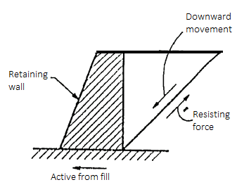
Fig 1: Active earth pressure
Passive earth pressure
- When the movement of the retaining wall is such that the soil tends to horizontally.

Fig 2: Passive earth pressure
Back fill:
- The material retained by retaining wall or supported structure is called back fill.
Surcharge
- The back fill may have its top surface horizontal or inclined. This back fill lying above horizontal place at elevation at top of wall is called as surcharge.
Assumptions made by Rankine for Earth Pressure:
Assumptions of the Rankine theory for active earth pressure are as follows:
- The soil mass is semi-infinite, homogeneous dry and cohesionless.
- The ground surface is plane which may be horizontal or inclined.
- The back of wall is vertical smooth.
- The wall yields about the base thus satisfies deformation condition for plastic equilibrium.
- The soil element is in state of plastic equilibrium i.e., on verge of failure.
Key Takeaways:
There are different types of earth pressures in the lateral direction according to the structure against which the soil is retained and according to the equilibrium conditions. These are: Earth pressure at rest, active earth pressure, passive earth pressure.
5.2 Classical Theories-Coulomb’s & Rankine’s approaches for frictional & C- soil:
soil:
Rankine’s State of Plastic Equilibrium in soils:
- Plastic equilibrium of soil: When every point of the soil body is on the verge of failure, then a body of soil is said to be in plastic equilibrium. In another word; every point of soil mass at rest condition is brought on the verge of failure by applying tension or compression, then the state so occurred is termed as a general state of plastic equilibrium.
- Rankine's was the only engineer who developed the concepts of plastic equilibrium to solve the stability problems.
- When plastic equilibrium conditions are realized in limited zones of soil, then it is termed as the local state of plastic equilibrium. The development of earth pressure on the retaining wall is part of backfill comes under the plastic equilibrium condition.
- Rankine considered a semi-infinite mass of soil comes under a horizontal surface and a vertical boundary as shown in Fig.
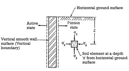
Fig 3: A semi-infinite mass of soil bound by a horizontal surface and a vertical boundary
- Rankine assumed the soil mass to be homogenous, cohesionless and dry
- Consider a soil element at a depth 'e' subjected to horizontal stress and vertical stress. There are no shear stresses acting on the horizontal and vertical planes, hence
 and
and  are the principal stresses.
 - When the soil mass as a whole is stressed in such way that the principal stresses of every point are in the same direction then it set up the network of failure plane. This network of failure plane is called as slip line field as shown in fig. Slip line field is equally inclined to the principal planes. When sufficient deformation of mass take place, only then plastic equilibrium is set up.
Key Takeaways:
Rankine's was the only engineer who developed the concepts of plastic equilibrium to solve the stability problems. When plastic equilibrium conditions are realized in limited zones of soil, then it is termed as the local state of plastic equilibrium
Active and Passive States due to wall movement:
When Wall Moves Away from Backfill:
- The value of horizontal stress decreases when away from backfill. If the expansion of soil element is more enough, then the value of horizontal stress (
 decreases to a minimum value and state of plastic equilibrium is set up called as active Rankine state as shown in Fig.
 - The Mohr's stress circle shows the state of elastic equilibrium as shown in Fig.
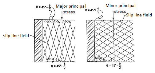
Fig 4: Active and passive Rankine state due to wall movement
Active Rankine state
- When the Mohr's stress circle touches the strength line drawn for the soil, then soil mass is active Rankine state.
- Note that plastic equilibrium state is developed due to decrease in the value of horizontal stress (
 ) it means it should be minor principal stress (
 ); vertical stress (
 ) and major principal stress (
 ), Minor principal stress due to decrease in the value of a, (horizontal stress) and Major principal stress.
When Wall Move towards the Backfill
- In such case, uniform compression is hold in the horizontal direction. There is an increase of horizontal stress (
 ) from its original value, but vertical stress (
 ) remains constant.
 - The diameter of stress circle becomes smaller due to increase of deformation and then reduces to zero. When the horizontal stress becomes more than vertical stress i.e.,
 ,then diameter of stress circle increases until a state of plastic equilibrium is reached. At this state, horizontal stress (
 ) is maximum and hence it is a major principal stress (
 ) but
) but  , (vertical stress) becomes minor principal stress
  .
.
Passive Rankine state
- When Mohr's stress circle drawn with
 , an
, an d touches the strength envelope, then it will be reached with the maximum value of
  This state of soil of reaching the maximum value of o, is called as passive Rankine state and pressure so developed is called as passive earth pressure (pp).
Key Takeaways:
There are two situations:
- When Wall Moves Away from Backfill
- When Wall Move towards the Backfill
Earth Pressure at rest:
- It has been shown that active pressure exerted on the retaining wall resulting from slight movement of the wall away from the backfill is associated with the expansion of the soil and passive pressure exists when the movement of the retaining towards the backfill which tends to compress the soil horizontally. In short, passive pressure is associated with compression.
- When a soil element at a depth 'z' below the ground surface not subjected to any strain in the natural state, then the soil element in this condition is called as soil at rest condition. Earth pressure at rest exerted on the back of a rigid retaining wall can be determined by using the theory of elasticity in which soil is assumed to be elastic, homogeneous, isotropic and semi-infinite.
- At rest condition, the earth pressure is expressed as follows,
P0=K0  z
z
Where K0=Coefficient of earth pressure
 z=Effective vertical stress at depth a
- Fig. Shows a retaining wall of height H at rest. It is possible to determine the lateral pressure by using theory of elasticity considering the soil mass to be homogenous, elastic isotropic and a semi-infinite material provided there is no displacements at all.
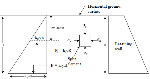
Fig 5: Earth pressure at rest
Key Takeaways:
Earth pressure at rest exerted on the back of a rigid retaining wall can be determined by using the theory of elasticity in which soil is assumed to be elastic, homogeneous, isotropic and semi-infinite.
Rankine’s theory: Earth pressure on retaining wall due to submerged backfill:
- Fig. Shows the retaining wall with backfill submerged by the natural water table saturated water. In such case, the lateral pressure is the sum of the two components.
These two components are as follows,
- Lateral pressure caused by submerged weight (
 ) of the soil, k, y, z and
 - Lateral pressure caused by water (
 )
)
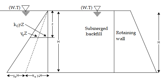
Fig 6: Submerged backfill
Here at any depth 2 below the horizontal surface-active pressure is given by the following expression,
Pa=Ka sz+
sz+ z
z
Where, Pa=active pressure
 s= submerged weight of soil (y)
 unit weight of water
Fig. Shows the active earth pressure distribution diagram at any depth 'z' and at the depth H.
The active pressure at the base of wall, where z H is given by the following expression,
Pa=Ka sH+
sH+ H
H
Key Takeaways:
The active pressure at the base of wall, where z H is given by the following expression, Pa=KaγsH+γwH
Backfill with Uniform Surcharge:
- Fig. Shows the retaining wall with horizontal backfill which is loaded by a uniformly distributed surcharge of intensity "q" by assuming the vertical pressure at any, depth is increased by "q".
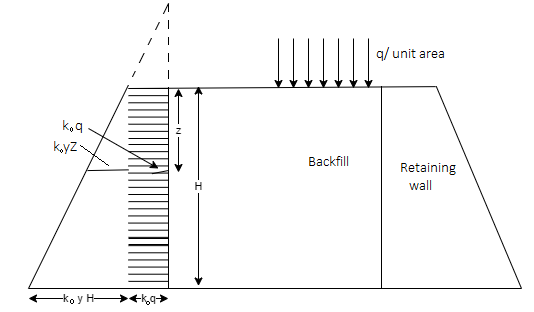
Fig 7: Retaining wall with backfill carrying uniform surcharge
∴Lateral active pressure at any depth 'z' is given by the following expression
Pa=Ka z+Kaq …. (At any depth z)
Where z =H, then, active pressure at the base is given
Pa=Ka H+Kaq ......(at height H from base of wall)
Layered backfill:
There are two cases for lateral pressure in layered soils which are as follows
- Same angle of shearing resistance
- Different angle of shearing resistance i.e.,

(a) Lateral pressure for layered cohesionless soil
1. Same angle of shearing resistance with cohesionless soil layers
- In this case, if
 values for retained materials are considered to be same, then the pressure distribution diagram shows the same values of lateral pressure at same depth for same value of vertical stress (
 ) as shown in Fig.
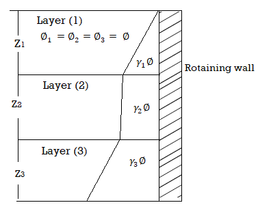
Fig 8: Layered soil with same angle of shearing resistance
(2) Different angle of sheering resistance with cohesionless soil layer
- When the upper and lower layers with different values of
 are considered, then the lateral pressure have a lower value for higher angle of friction and higher value of lateral pressure for a smaller angle of friction.
Fig. Shows layered soil with different angle of shearing resistance.
Let consider for the two layers as shown in Fig.
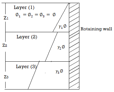
Fig 9: Layered soil with different angle of shearing resistance
For these two layers, ka1 > ka2, the active pressure are as follows:

Key Takeaways:
There are two cases for lateral pressure in layered soils which are as follows
- Same angle of shearing resistance
- Different angle of shearing resistance i.e.,

Coulomb’s Wedge theory:
- Rankine's theory of earth pressure considers the theory of plasticity approach to find the stresses in the soil mass. The Rankine's theory is only applicable to smooth vertical wall. There are various ideal conditions used in practice of retaining wall problems.
- Coulomb's wedge theory can be applied to determine the active earth pressure for a backfill possessing both cohesion and effect of friction between the backfill and wall.
- Coulomb's theory considers a dry non-cohesive or dry cohesionless inclined backfill in which the lateral earth pressure required to balance the equilibrium of a sliding wedge with a slip surface can be determined.
Basic Assumptions of Coulomb's Wedge Theory:
Following are the various basic assumptions of coulomb's wedge theory
- The backfill is dry, non-cohesive (i.e., cohesionless), homogeneous, isotropic, soil (i.e., equal elastic properties in all direction). The backfill is elastically undeformable but breakable
- Backfill possessing both cohesion and internal friction or slip surface
- The failure surface or slip surface is a plane surface which passes through the heel of wall
- Failure is two dimensional. The backfill surface is plane and can be inclined.
- The position and the line of action of the earth pressure or direction of resultant earth pressure are known. The back of the wall can be inclined to the vertical
- The sliding wedge is itself considered as rigid body and the earth pressure is obtained by considering the limiting equilibrium of the sliding wedge as a whole.
Shape of the failure surface:
- The shape of the failure surface which makes one of the boundaries of the sliding wedge is actually curved near the bottom of the wall in both active and passive cases due to wall friction. Hence there is curvature in slip surface due to friction itself.
Active earth pressure (Pa) for C= 0 backfill:
- In case of cohesionless backfill (i.e., non-cohesive backfill, C= 0), there are three forces kept the wedge under equilibrium. These three forces are:
- Weight of wedge (W)
- Soil reaction force (R) on the failure plane and
- Earth pressure reaction (P)
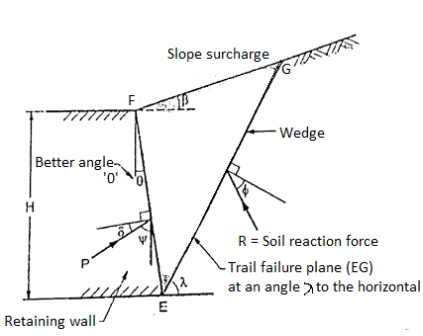
Fig 10: Wedge under the action of three forces, W, R and P
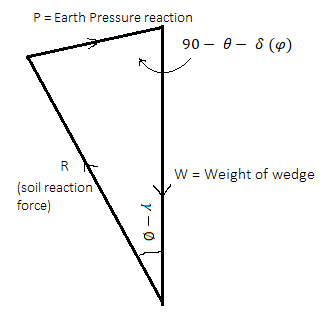
Fig 11: Force triangle W, R and P
- Fig. Shows the force triangle drawn from the known value of W and direction of all the three forces and magnitude of P is determined for the assumed trial wedge.
- There is maximum wall reaction for critical step, plane and the wall should resist the maximum lateral pressure before it moves outward. Hence the maximum value of P is the active earth pressure.
- Note that in case of passive earth pressure, the wall should exert the smallest force so as to move the wedge for critical slip surface.
- In general; one of the drawbacks in coulomb's theory that it does not satisfy the static equilibrium condition. When the sliding surface is assumed to be plane, then three forces i.e., weight of wedge (W), soil reaction (R) and the earth pressure (P) acting on the sliding wedge do not meet at a common point. However, based on the other assumption, the coluomb's theory is most effective in practice.
Active earth pressure for C-  backfill:
- Coulomb's theory can be used to find out the active earth pressure (P) for a backfill possessing both cohesion and friction.
- Following are the various forces acting on the wedge of soil at failure for C- backfill
- Weight of soil wedge (W)
- Earth pressure reaction (P) acting at an angle below the normal
- Soil reaction (R) on the failure plane acting an angle below the normal
- Force of adhesion (C2) between soil and wall
- Cohesive force (C) on the failure plane

Fig 12: Forces acting on soil wedges at failure
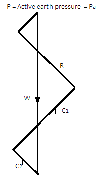
Fig 13: Polygon of forces
The force polygon as shown in Fig. Is drawn from the known values of W. C, C, and direction of all five forces and the value of p i.e., active earth pressure can be determined by closing side of a polygon.
Here C1=Cu x length of the slip plane EG
C2= unit adhesion (Cw) x length of wall in contact with the soil EF
Key Takeaways:
Rankine's theory of earth pressure considers the theory of plasticity approach to find the stresses in the soil mass. The Rankine's theory is only applicable to smooth vertical wall. There are various ideal conditions used in practice of retaining wall problems. Coulomb's wedge theory can be applied to determine the active earth pressure for a backfill possessing both cohesion and effect of friction between the backfill and wall.
- Rankine's theory can also be applied for backfill with sloping surface at the constant angle
 to the horizontal.
 - To determine the active earth pressure in such case by Rankine's theory, an additional assumption is considered that the vertical stress and lateral pressure are conjugate stresses.
- The active earth pressure at a depth 'z' acting parallel to the slope is given by the following expression:
Pa= Ka γz , ...For sloping surface
Where, Ka=
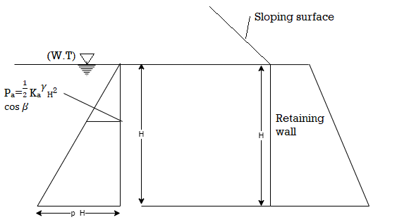
Fig 14: backfill with sloping surface
For horizontal ground surface;  =0
=0
Ka=
The total active pressure P, for a retaining wall having height 'II' is given by the following expression:
Pa= Ka
Ka H2
H2 
Rebhan’s graphical method of determination of earth pressure:
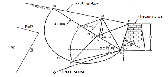
Fig 15 Graphical method by poncelet construction based on Rebhan’s principles
- In 1871, Rebhan's represented a graphical method to determine the total active pressure (Pa) based on Coulomb's theory on a rough wall with a cohesionless, homogenous and inclined backfill as shown in Fig.
- Fig. Shows poncelet construction for non-cohesive soils or cohesionless soils (C = 0) based on the principles made by Rebhan.
Procedure of graphical method:
Following is the procedure of construction to find out the active earth pressure by graphical method refer Fig.
- Draw a retaining wall to a suitable scale and measure the backfill surface angle for required position as shown in Fig.
- Draw a -line EG such that it intersects the backfill surface at G.
- Draw a semi-circle BQG by taking diameter as EG.
- Draw the pressure line 'EO' at an angle of (a-5) with respect to o-line.
- Draw FI parallel to pressure line 'EO'.
- Draw a perpendicular to EG at I such that it cut the semi-circle at T.
- With centre E and radius ET, draw an are such that it cut EG at J.
- Draw JM parallel to FI
- Now EM is a rupture line
- Taking as a centre and IM as the radius draw at a such thar EG at L
After this construction from step 1 to 10, it shows the  LIM. Area of
  LIM in its natural units multiplied by the unit weight of the soil (
 ) gives the active earth pressure (Pa) as follows:
Pa=Area of triangle LJM= *JM*MN
Where,  =unit wt of the soil
JM length of a triangle LJM
MN=height of  LJM
LJM
Pa=Active earth pressure
Key Takeaways:
In 1871, Rebhan's represented a graphical method to determine the total active pressure (Pa) based on Coulomb's theory on a rough wall with a cohesionless, homogenous and inclined backfill.
- Stability of slopes plays an important role in the earth embankments or in cuttings required for railways roadways, earthen dams, river training, levees, highways Slopes may be artificial or may also natural as in Hillside and valleys, coastal, river cliffs etc. Hence in case of slopes may be artificial or natural, the force exist which tend to cause the soil to move from high points to low points.
- If actual movement of soil mass occurs, it is a slop failure Force of gravity and seepage force are mainly responsible to cause the instability of Lipes in the areas of seismic activity, the earthquake forces is also an important factor causing instability of slope.
- Stability analysis is made commonly by using a Lit equilibrium approach. In this method, the shearing resistance required to maintain a limiting equilibrium condition is compared with the available shearing strength of the soil.
Actuating force
- The forces causing the instability induces the shearing stresses throughout the soil muss is termed as actuating force. Gravity force, seepage force and earthquake force are actuating forces.
Slip surface
- The surface along which the failure occurs in the form of mass movement of soil due to larger shearing stress is called as slip surface.
- Analysis of stability of slopes requires the determination of the actuating forces such a gravity forces, seepage forces and earthquake forces
Key Takeaways:
In case of slopes may be artificial or natural, the force exist which tend to cause the soil to move from high points to low points then it is termed a
Infinite slope:
- The boundary surface of a semi-infinite soil mass having the constant soil properties for all identical depths below the surface is called as infinite slope.
- The Fig. Shows an infinite slope with its traverse extent large as compared to the depth of its failure zone.
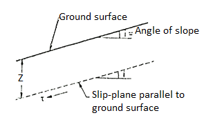
Fig 16: An infinite slope
- Slopes extending to infinity do not exist in nature.
Finite slopes:
- When the slope is having the limited extent, then it is called as finite slopes. Most man-made embankments and road or railway, cuts etc. are finite in extent.
- Examples of finite slopes: Inclined faces of earth dam, embankments, cuts etc. are the examples of finite slopes.
- Fig. Shows the finite slopes.

Fig 17: Embankment

Fig 18: Cut slope
- There are various failure types of infinite and finite slopes. The failure of the slopes can be in the form of plane slide (i.e., translational slide) or rotational slick failure along essentially planer surface is called translational slides:
Modes of failure in Infinite slopes
- For an infinite slope in a homogeneous soil, failure of slope take place due to sliding of the soil mass along a plane parallel to the ground surface at a certain depth. In short, for long steep slope, failure of slope will be along a surface parallel to the ground surface and in such case sliding surface is plane as shown in Fig.
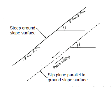
Fig 19: Failure in infinite slope
Modes of failure in Finite slopes:
- There are three basic modes of failure in case of finite slopes.
- Face failure or slope surface
- Toe failure
- Base failure
1. Face failure or slope surface
- When the failure occurs along a surface of sliding interests the slope above the toe, then slide is termed as slope failure or face failure.
- This type of failure occurs due to very high slope angle (i) and soil close to the toe is quite strong or the soil the upper part of the slope is comparatively weak.
- Fig. Shows plane slide and rotational slide respectively in case of slope failure, face failure.
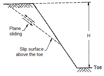
Fig 20: Plane side of Face failure

Fig 21: Rotational side of face failure
2. Toe failure
- When the failure surface passes through the toe of slope, then it is termed as toe failure. Toe failure is most common mode of failure and occurs in steep slope consisting of the homogeneous solid mass above and below the base.
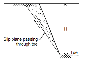
Fig 22: Plane side of Toe failure
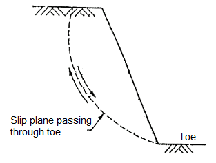
Fig 23: Rotational side of toe failure
3. Base failure
- When the failure surface passes below the toe of slope, then it is termed as base failure. This type of failure occurs due to the weaker material or relatively weak and soft soil at the base than that of slope. Fig. Shows the base failure.
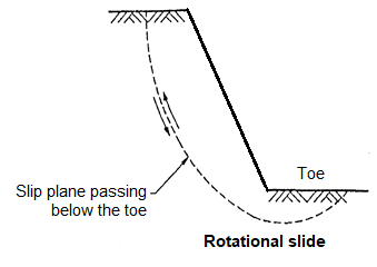
Fig 24: Modes of base failure
Key Takeaways:
1.Modes of failure in infinite slopes
2.Modes of failure in Finite slopes:
There are three basic modes of failure in case of finite slopes.
- Face failure or slope surface
- Toe failure
- Base failure
- Culmann's graphical method is rather general method than Rebhan's method. This method is same as the trial wedge method. The force triangle or force polygon can directly be constructed on o-line EG considering EG as a load line.
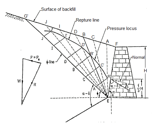
Fig 25: Culmann’s graphical method for determining active earth pressure
- This method can be used to evaluate the coulomb's earth pressure fr ground sa face of any configuration, different types of surcharges and layered backfills.
- Fig. Shows the Culmann's graphical method of determine active earth pressure (P) for non-cohesive soils or cohesionless soils (i.e., C= 0)
Graphical construction procedure:
- Various steps involved in the procedure are as follows:
- EF it a retaining wall as shown in Fig. 5 in 1(a) drawn to a suitable scale.
- Draw -line EG at an angle with respect to horizontal.
- Mark on EG, the distances EA, EC, ED, EL, EJ etc. to a suitable scale representing the weight of wedges EFA, EFC, EFD, EFI, EFI etc. respectively.
- Draw lines parallel to pressure line ET from the points A, C, D, I J such that it intersects assumed rupture line EA, EC, ED, EI, EJ at points A, C, D,1, J respectively.
- Then point A', C, D, I', J' are joined by a smooth curve representing the pressure locus.
- Select point B' on the pressure locus in such way that the tangent to the curve at this point parallel to line EG
- Draw B'B parallel to the pressure line ET. The magnitude of B'B" itself in its natural units gives the active earth pressure (Pa)
- Points E and B' are joined and extended further so as to meet the surface of backfill at B Then EB is the rupture line.
- Note that, for the plane backfill surface, the point of application of active earth pressure (Pa) is at a height 1/3 of from the base of retaining wall.
Key Takeaways:
Culmann's graphical method is rather general method than Rebhan's method. This method is same as the trial wedge method.
- The slipping along the slip is at critical equilibrium is resisted by the total cohesive force (CL). This force is proportional to the cohesion C and the height H of the slope.
- The force responsible for instability of i se slope is the weight of the wedge which is equal to the unit weight
 .
.
∴Weight of the wedge  H2
H2
- Let (F.S) c be the factored of safety for cohesion.
We know,
=
= =Sn …. (1)
- Here
 is the dimensionless quantity which is called as Tayler's stability number (Sn).
 - Consider Cm be mobilized unit cohesion which is essential so as to have the equilibrium of a slope having height H.
Cm= … (2)
… (2)
Where C= Cohesion:
(F.S) c= Factor of safety with respect to cohesion
Hence the Equation (1) can be written as follows:
Sn = =
= …. (3)
- Also, for critical height H the factor of safety with respect to height (H) is equal to the factor of safety with respect to cohesion (C)
∴ (F.C) c =Hc/H… (4)
Where (F.C) c = Factor of safety with respect to cohesion
There Equation (3) becomes as
Sn = =
= … (5)
… (5)
- Taylor analyzed the friction circle method and determined the values of stability number (Sn) for finite slopes and prepared the table as shown in Table gives the values of Sn for the various values of and slope angle (i).
- When a dangerous circle passing below the toe occurs, then stability numbers such as (0.145). (0.068) and (0.023) mentioned in Table indicates the most dangerous circle through toe.
- The Fig. Shows Taylor's stability number charts for
 =0
=0
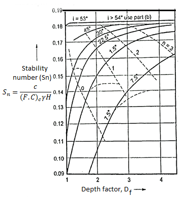
Fig 26: Taylor’s stability number charts, =0 with respect to depth factor
- The Modified Bishops approach is barely distinct from the regular approach of slices in that everyday interplay forces among adjoining slices are assumed to be collinear and the consequent interslice shear pressure is zero.
- The technique become proposed with the aid of using Alan W. Bishop of Imperial College.
- The constraint delivered with the aid of using the everyday forces among slices makes the hassle statically indeterminate.
- As a result, iterative techniques need to be used to clear up for the thing of protection.
- The approach has been proven to provide thing of protection values inside some percentage of the "correct" values.
Numericals:
Q. Compute the active earth pressure at a depth of 4.5 m in a sand whose angle of friction is 37 degree and Density of 15.60 KN/m3 in dry state.
Soln.:
Given:
H = 4.5 m,  = 37⁰,
 = 15.60 kN/m²
To compute the active earth pressure at a depth H in dry state
We know, From Rankine's theory, active earth pressure (Pa) at a depth H is given by:
 … (1)
… (1)
Where Ka=coefficient of active earth pressure=
∴
Substituting
Ka = 0.248 in Equation (1), we get
Pa = 0.248 x 15.60x4.5
∴Pa = 17.4 kN/m3
Q. A retaining wall with a vertical smooth back is 8m high It supports a cohesionless soil with  30% The surface of soil is horizontal. Determine the thrust in the wall.
Soln.:
Given:
H=8m,  = 19 kN/m²,
  =30°.
=30°.
To determine the thrust (Pa) in wall: From the given data, draw the Fig. For better understanding.
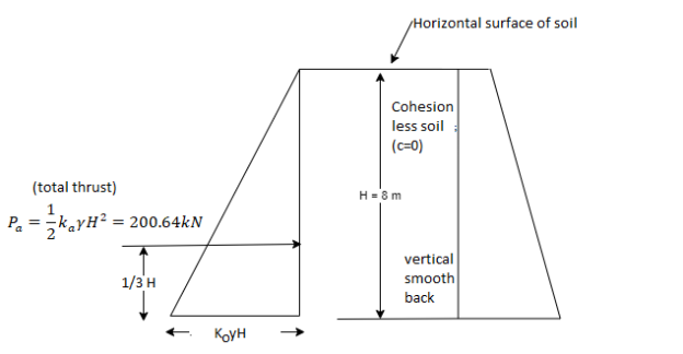
Fig 27: Active earth pressure distribution diagram and retaining wall resp.
For the condition given here, Rankine's theory disregards the friction between the soil and back of the wall. Total thrust (Pa) per meter of wall by Rankine's theory of earth pressure is given by:
Pa= …(1)
…(1)
Where ka = coefficient of active earth pressure=
Ka=
Substituting the ka = 0.33, H=8 m and  = 19 kN/m3 in Equation (1), we get
Pa=
∴Pa=200.64 KN per meter of wall
Active earth pressure (Pa) at the base of wall is given by:
 …. (Active earth pressure at the base of wall)
Pa = 0.33 x 19 x8 = 50.16 kN/m2
∴Pa=50.16KN/m2
Q. A smooth vertical wall retains a level backfill with  18 kN/m3 and c=0 to a depth of 8 m: Draw the lateral earth pressure diagram, and compute the total active earth pressure with its point of application
Soln.:
Given:  = 18 kN/m²,
  = 33
= 33 .
.
C=0 (i.e. cohesionless soil), H=8 m
To compute total active earth pressure (Pa) with its point of application
For the condition given here, Rankine's theory disregards the friction between the soil and back of the wall. Note that given wall is a smooth vertical wall. Hence use Rankine's theory of earth pressure.
There is no surcharge being a level backfill.
Total active earth pressure (Pa) is given by the Rankine's theory of earth pressure as,
Pa = ….(1)
….(1)
Where ka= coefficient of active earth pressure=
Ka=
Substituting Ka= 0.294, = 18 kN/m² and H=8m in equation (1)
We get, Pa =
Hence total active earth pressure (Pa) is 169.34 kN per metre length of wall.
Point of application of Pa is  from the base of wall.
∴Point of application of Pa= x8=2.666
 2.67 m = 2.67m from base of wall
Draw Lateral earth pressure diagram
Pa= active earth pressure at the base of wall =  0.294 x 18x8=42.33 kN/m²
From the obtained values of active earth pressure, lateral earth pressure diagram is drawn as shown in Fig.
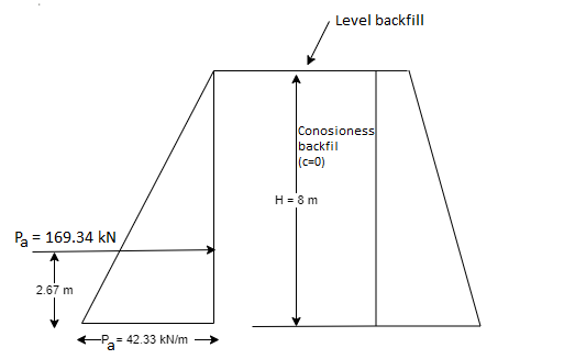
Fig 28: Lateral earth pressure and smooth vertical wall resp.
Q. A smooth vertical wall retains a level surface with  =18 kN/m3
  30
30 to a depth of 8 m. Draw the lateral pressure diagram and compute the total active pressure in dry condition and when water table rises to the GL Assume=22 kN/m3.
Soln.:
Given: H=depth=8m;  =22 kN/m3,
  = 30°;
  = 18 kN/m3
To compute the total active pressure (Pa) in dry condition:
Ka= Coefficient of active earth pressure= 
∴Total active earth pressure in dry condition (Pa)=  =
=  × 18 × 8
∴Pa= 48 kN/m²
To compute the total active earth pressure when water table rises to the GL (i.e. submerged soil

:. Total active earth pressure (Pa) =  =
=  x12x8+10x8
∴Pa = 112 kN/m²
Q. A cohesionless soil deposit having unit weight of 15 KN/m3 and angle of internal friction  . Determine the active and passive lateral pressure intensities at depth of 10 m.
Sol:
Given:
 = unit weight = 15 kN/m3,
H = 10m
 Angle of internal friction = 30
 ,
,
To determine coefficient of active earth pressure (Ka) and coefficient of passive earth pressure (Kp)
Ka= Coefficient of active earth pressure= 
Kp= Coefficient of passive earth pressure= 
To determine active and passive lateral pressure intensities at a depth of 10 m
1) Active lateral pressure (Pa)
Pa=  =
=  × 15 × 10
∴Pa=50KN/m2
2) Passive lateral pressure (Pp)
Pp=  = 3× 15 × 10
∴Pp=450KN/m2
References:
- V.N.S Murthy-Soil Mechanics and Foundation Engineering (fifth Edition)
- K.R.Arora-Soil Mechanics and foundation Engineering
- Alam Singh- Modern Geotechnical Engineering
- C.Venkataramaiah-Geotechnical Engineering
- Gopal Ranjan and A.S.R. Rao-Basic and Applied soil mechanics