Unit 1
Wave Optics
Electromagnetic waves:
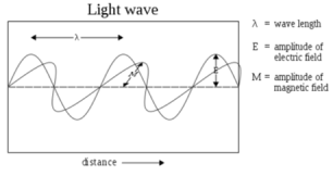
• Electromagnetic waves or EM waves are waves that are created as a result of vibrations between an electric field and a magnetic field.
• When the electric field comes in contact with magnetic field electromagnetic waves are formed,they are known as ‘electromagnetic’ waves.
• The electric field and magnetic field of an electromagnetic wave are perpendicular to each other. They are perpendicular to the direction of the EM wave.
• These waves travel with a constant velocity of 3.00 x 10⁸ m/s in vacuum. They are deflected neither by the electric field, nor magnetic field. They are capable of showing interference or diffraction.
• An electromagnetic wave can travel through air, solid material or vacuum. It does not need a medium to propagate or travel from one place to another.
• Mechanical waves need a medium to travel. EM waves are 'transverse' waves. This means that they are measured by their amplitude and wavelength.
|
Fig 1. Electromagnetic wave
Properties of EM Waves:
- All the electromagnetic waves travel at the same speed through empty space. The speed is called the speed of light.
- Wavelength is defined as the distance between the corresponding points of adjacent waves.
- Wave frequency is the number of waves that pass a fixed point in a given amount of time.
- The energy of electromagnetic waves depends on their frequency. Low frequency waves have little energy. High frequency waves have lot of energy and are potentially harmful.
|
Figure 2 – Wavelength
The wave speed is given by
Frequency = Speed / Wave length
Wave length = speed x frequency.
The highest point of a wave is known as 'crest', whereas the lowest point is known as 'trough'.
Electromagnetic spectrum:
The electromagnetic waves are classified and arranged according to their various wavelengths/frequencies, this classification is known as electromagnetic spectrum.
Examples of EM waves are radio waves, microwaves, infrared waves, X-rays, gamma rays.
|
Figure 3. Electromagnetic spectrum
- Electromagnetic spectrum is the distribution of electromagnetic radiation with respect to frequency or wavelength.
- Even though electromagnetic waves travel at the speed of light in a vacuum, they have wide range of frequencies, wavelengths, and photon energies.
- The electromagnetic spectrum comprises the span of all electromagnetic radiation and consists of many subranges, commonly referred to as portions, such as visible light or ultraviolet radiation.
- The various portions carry different names based on differences in behavior in the emission, transmission, and absorption of the corresponding waves and also based on their different practical applications.
The interference between light reflected from different surfaces of a thin film and their effect is known as thin-film interference.
The most prominent are when light interacts with a thing having the size similar to its wavelength.
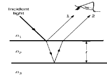
A thin film having a thickness t is smaller than few times the wavelength of light λ. Since colour is associated indirectly with λ and because all interference depends the same way on the ratio of λ to the size of the object involved, we expect to see different colours for different thicknesses of a film, as shown in Figure.
|
Figure 4. The light reflected from the top and bottom surfaces of a film can interfere.
As the figure the light striking a thin film is partially reflected (ray 1) and partially refractedat the top surface. The refracted ray is partially reflected at the bottom surface and emerges as ray.
These rays interfere in such a way that depends in the thickness of film and the indices of refraction of the various media.
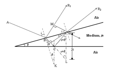
Consider a thin film of uniform thickness ‘t’ and refractive index µ bounded between air. The monochromatic ray AB is made incident on the film , at B part of ray is reflected (R1) and part is refracted along BC.
The beam that is BC undergoes partial reflection and partial refraction , the reflected beam CD moves again and undergoes partial reflection and partial refraction at D.
The refracted beam R2 moves in air. These two reflected rays R1 and R2 produce interference pattern.
|
Figure 5. Thin film Interference
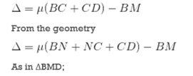
The optical path difference between the two reflected rays R1 and R2 will be
From the geometry
As in ΔBMD;
According Snell’s Law,
Or Thus
|
Correction on account of phase change at reflection:
When a beam is reflected from a denser medium (ray R1 at B), a path changes of  /2 occur for the ray.
Therefore, the true path difference is

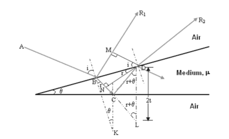
The wedge-shaped film has a thin film of varying thickness, having thickness zero at one end and increases at the other. The angle of wedge is  .
.
|
Figure 6. Wedge shape interference
The wedge-shaped film has a thin film of varying thickness having thickness zero at one end and increases at the other. The angle of the wedge is  .
.
The optical path difference between the reflected rays R1 and R2 is
According Snell’s Law,
Or Thus
AsinΔNDL
|
- Testing optical flatness
- The flatness of the working surface of an optical flat is tested by comparing its flatness with a master flat of known flatness.
- The testing is usually carried out by observing the interference fringes using monochromatic light source.
- If the optical flat under test has perfectly flat surface then the fringes observed will be a straight line.
|
Figure 7. Flatness Test
- Parallelism Test:
- The parallelism of working surfaces of type B optical flats can be tested by Fizeau Interferometer method.
- In this method the light from mercury vapour lamp is focused on to an opening in the eyepiece and is
- The reflected light strikes the collimating lens which collimates it and throws it further on the flat under test. The flat under test is placed on the table.
- The table is arranged such that the beam strikes the surfaces of the flats perpendicularly.
Anti-reflection coating:
- Thin film anti-reflection coatings greatly reduce the light loss in multi-element lenses by making use of phase changes and the dependence of the reflectivity on index of refraction.
- A single quarter-wavelength coating is that creation of double interface by means of a thin film gives two reflected waves.
- If these waves are out of phase they partially or totally cancel. If the coating is a quarter wavelength thickness and the coating has an index of refraction less then the glass it is coating has two reflections which are 180 degrees out of phase.
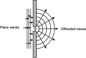
- Diffraction is a process that occurs when wave encounters an obstacle with its size close to its wavelength as shown in figure.
- It is described as the apparent bending of waves around small obstacles and the spreading out of waves past the small openings.
- Diffraction occurs with all waves which includes sound waves, water waves, and electromagnetic waves such as visible light, x-rays and radio waves.
|
Figure 8. Diffraction
- The examples of diffraction include closely spaced tracks on DC , or DVD which act as diffraction grating which form the pattern when looking at the disc.
- Diffraction in atmosphere also causes bright ring to be visible around bright light source like the sun or moon.
- By using light from compact source, a shadow of the solid object causes small fringes near the edges. The speckle pattern observed when the laser light falls on optically rough surface is called diffraction phenomenon.
- All these are the consequences of light wave.
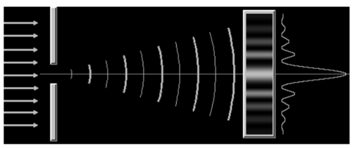
When light passes through a single slit having width w is of the order of the wavelength of the light, it can be observed that a single slit diffraction pattern on a screen that is a distance L >> w away from the slit.
The intensity is a function of angle. Huygens' principle says that each part of the slit can be thought of as an emitter of waves. All these waves interfere to produce the diffraction pattern.
When crest meets crest, we have constructive interference and when crest meets trough, we have destructive interference.
|
Figure 9. Single slit
- The wave-fronts at larger distance from the point source are essentially plane waves. This is called the Fraunhofer regime and the diffraction pattern is called Fraunhofer diffraction.
- The positions of all maxima (constructive interference) and minima (destructive interference) in the Fraunhofer diffraction pattern can be calculated easily.
- The Fraunhofer approximation, however, is only valid when the source, aperture, and detector are all very far apart or when lenses are used to convert spherical waves into plane waves.
- Conditions for maxima and minima
|
Fig(a)
|
Fig (b)
Fig 10 . Slit diagram
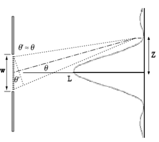
- Consider a slit of width w, as shown in the diagram. A plane wave is incident from the bottom and all points oscillate in phase inside the slit.
- For light leaving the slit in a particular direction defined by the angle θ, there is a possibility that destructive interference happens between the ray at the right edge (ray 1) and the middle ray (ray 7).
- To arrive at a distant screen perpendicular to the direction of propagation of the rays, the rays coming from different points inside the slit have to travel different distances.
- They have a different optical path length. If ray 7 has to travel an extra distance of one-half wavelength (λ/2) compared to ray 1, then ray 1 and ray 7 destructively interfere. Crest meets trough.
- The optical path length of a light ray traveling from point A to point B is defined as c times the time it takes for the ray to travel from A to B.
- In free space the optical path length is just the distance d between the points. In a transparent medium with index of refraction n, it equals n times this distance, OPL = nd, because the light moves with speed c/n.
If the optical path length of two rays differs by λ/2, then the two rays interfere destructively.
For ray 1 and ray 7 to be half a wavelength out of phase we need
(w/2)sinθ = λ/2 or
w sinθ = λ.
Destructive interference produces dark fringes. Dark fringes in the diffraction pattern of a single slit are found at angles θ for which
w sinθ = mλ,
where m is an integer, m = 1, 2, 3, ... . For the first dark fringe we have w sinθ = λ.
When w is smaller than λ , the equation w sinθ = λ has no solution and therefore no dark fringes are produced.
If the interference pattern is viewed on a screen at a distance L from the slits, then the wavelength can be found from the spacing of the fringes.
We have λ = w sinθ/m and sinθ = z/(L2 + z2)½), or
λ = zw/(m(L2 + z2)½
where z is the distance from the centre of the interference pattern to the mth dark line in the pattern.
If L >> z then (L2 + z2)½ ~ z/L and we can write
λ = zw/(mL).
|
Fig 11. Slit for L>> z
Diffraction pattern
λ = a sin θ≈aθ
⇒θ = yD = λa
⇒ y = λDa
The width of the central maximum is simply twice this value
⇒ Width of central maximum = 2λDa
⇒ Angular width of central maximum = 2θ = 2λa
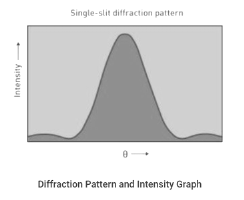
The diffraction pattern and intensity graph is shown below.
|
Fig 12. Single-silt diffraction pattern.
- When a planar wave passes through the slit it bends or creates a spherical wave front. This means that light is scattered in all directions.
- Suppose the material surface is irregular then the resulting planar waves scatter randomly and no interference pattern emerges at macroscopic level.
- In case material posses surface patterns, the regularity of patterns produces diffracted wave fronts to interact in a repeating or non-random way.
- This effect is termed as diffraction grating. Here some wavelengths of light are greatly amplified, while some will be cancelled out.
- The Grating Equation
- The dispersion of a grating is governed by the grating equation, usually written as:

- where: n is the order of diffraction,
- λ is the diffracted wavelength
- d is the grating constant (the distance between successive grooves)
- θi is the angle of incidence measured.
Resolving Power:
It is defined as the inverse of the distance or angular separation between two objects which can be just resolved when viewed through the optical instrument.
Resolving Power of Telescope:
In telescopes, very close objects such as binary stars or individual stars of galaxies subtend very small angles on the telescope. To resolve them we need very large apertures. We can use Rayleigh’s to determine the resolving power. The angular separation between two objects must be
△θ = 1.22 λd
Resolving power = 1△θ = d1.22 λ
Thus, higher the diameter d, better the resolution. The best astronomical optical telescopes have mirror diameters as large as 10m to achieve the best resolution. Also, larger wavelengths reduce the resolving power and consequently radio and microwave telescopes need larger mirrors.
- Conditions for maxima or minima
- To obtain a good image, the point sources must be resolved which means that the point sources must be imaged in such a manner that their images are sufficiently far apart that their diffraction patterns do not overlap.
- For this, the minimum distance between images must be such that the central maximum of the first image lies on the first minimum of the second and vice versa. Such an image is said to be just resolved. This is the famous Rayleigh criterion.
- The criterion is given by the above formula as:
- sin θR ≈ θR≈ 1.22 λd
Polarization of light
- A light wave is an electromagnetic wave that travels through the vacuum of outer space. Light waves are produced by vibrating electric charges. An electromagnetic wave is a transverse wave that has both an electric and a magnetic component.
- As an electromagnetic wave traveled towards you, the vibrations of the slinky occurs in more than one plane of vibration Indeed, the coils of the slinky would be vibrating back and forth as the slinky approached but these vibrations would occur in a single plane of space.
- That is, the coils of the slinky might vibrate up and down or left and right. yet regardless of their direction of vibration, they would be moving along the same linear direction as the slinky.
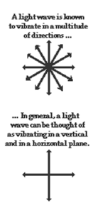
- If a slinky wave were an electromagnetic wave, then the vibrations of the slinky would occur in multiple planes. Unlike a usual slinky wave, the electric and magnetic vibrations of an electromagnetic wave occur in numerous planes.
- A light wave that is vibrating in more than one plane is referred to as unpolarized light. Light emitted by the sun, by a lamp in the classroom, or by a candle flame is unpolarized light.
- Such light waves are created by electric charges that vibrate in a variety of directions, thus creating an electromagnetic wave that vibrates in a variety of directions.
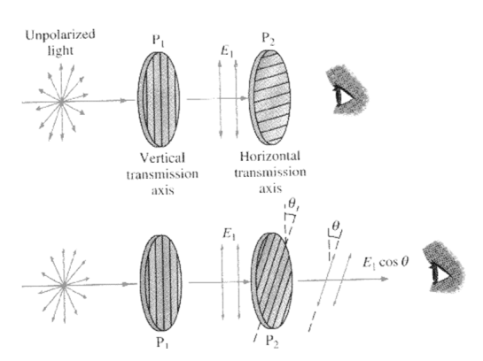
When light falls on a polarizer, the transmitted light gets polarized. The polarized light falling on another Polaroid, called analyzer, transmits light depending on the orientation of its axis with the polarizer.
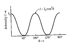
The intensity of light transmitted through the analyzer is given by Malus’ law. The law describes how the intensity of light transmitted by the analyzer varies with the angle that its plane of transmission makes with that of the polarizer.
The law can be stated in words as follows:
The intensity of the transmitted light varies as the square of the cosine of the angle between the two planes of transmission.
|
Figure13.Polarizer
|
If Ao is the amplitude of the incident light and (At) is amplitude of the light transmitted through the analyzer; which in inclined at an angle θ with the polarizer then (fig 2 & 3),
At=Ao Cosθ..................................1
As Intensity ∝(amplitude)2
It = At2 = Ao2Cos2θ = IoCos2θ.................2
where It is the intensity of the light transmitted through the analyzer; and Io is the intensity of the incident plane polarized light.
Consider the two extreme cases illustrated by this equation:
1 If θ is zero, the second polarizer (analyzer) is aligned with the first polarizer, and the value of cos2θ is one. Thus, the intensity transmitted by the second filter is equal to the light intensity that passes through the first filter. This case will allow maximum intensity to pass through.
2 If θ is 90˚, the second polarizer (analyzer ) is oriented perpendicular to the plane of polarization of the first filter, and the cos2(90˚) gives zero. Thus, no light is transmitted through the second filter. This case will allow minimum (zero) intensity to pass through.
The light intensity cannot be measured directly. The light energy is converted into electrical energy using photo detectors such as a photo cell or light dependent resistor (LDR).
In such photo detectors the current produced is directly proportional to the light intensity.
It ∝ current
It = K *current
The constant K appearing here is nothing but the conversion efficiency of photo detector.
Using this concept Malus’s law (equations 1 and 2) is verified in this experiment. The angles are noted experimentally from the dial fitted to the Polaroids.
|
Figure 14.Mauls Law
- θd is the angle of diffraction measured from the normal.
- The diagram above shows the orders of the diffracted wavelength. As well as positive orders, light can also be diffracted in the opposite direction (i.e. n = -1, -2 etc.)
- Higher orders may also appear but these decrease in intensity. Usually the first order lines (n=1 or n=-1) are the most intense.
LCD
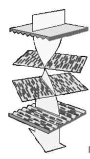
Most liquid crystals are organic compounds consisting of long rod-like molecules which, in their natural state, arrange themselves with their long axes roughly parallel.
The alignment of the molecules follows the grooves, so if the grooves are exactly parallel, then the alignment of the molecules also becomes exactly parallel.
|
Figure 15. LCD
In their natural state, LCD molecules are arranged in a loosely ordered fashion with their long axes parallel.
However, when they come into contact with a grooved surface in a fixed direction, they line up in parallel along the grooves.
The first principle of an LCD consists of sandwiching liquid crystals between two finely grooved surfaces, where the grooves on one surface are perpendicular (at 90 degrees) to the grooves on the other.
If the molecules at one surface are aligned north to south, and the molecules on the other are aligned east to west, then those in-between are forced into a twisted state of 90 degrees. Light follows the alignment of the molecules, and therefore is also twisted through 90 degrees as it passes through the liquid crystals.
The second principle of an LCD relies on the properties of polarising filters and light itself. Natural light waves are orientated at random angles
. A polarising filter is simply a set of incredibly fine parallel lines. These lines act like a net, blocking all light waves apart from those (coincidentally) orientated parallel to the lines.
A second polarising filter with lines arranged perpendicular (at 90 degrees) to the first would therefore totally block this already polarised light.
Light would only pass through the second polariser if its lines were exactly parallel with the first, or if the light itself had been twisted to match the second polariser.
A typical twisted nematic (TN) liquid crystal display consists of two polarising filters with their lines arranged perpendicular (at 90 degrees) to each other,
But in-between these polarisers are the twisted liquid crystals. Therefore, light is polarised by the first filter, twisted through 90 degrees by the liquid crystals, finally allowing it to completely pass through the second polarising filter.
However, when an electrical voltage is applied across the liquid crystal, the molecules realign vertically, allowing the light to pass through untwisted but to be blocked by the second polariser. Consequently, no voltage equals light passing through, while applied voltage equals no light emerging at the other end.
|
Figure 16. Construction
The crystals in an LCD could be alternatively arranged so that light passed when there was a voltage, and not passed when there was no voltage. However, since computer screens with graphical interfaces are almost always lit up, power is saved by arranging the crystals in the no-voltage-equals-light-passing configuration.
REFERENCE
1. Engineering Physics-Avadhanulu, Kshirsagar, S. Chand Publications
2. A textbook of optics- N Subrahmanyam and BriLal , S. Chand Publications
3. Engineering Physics- Gaur, Gupta, Dhanpat Rai and Sons Publications
