Unit - 10
Mechanics of Solids
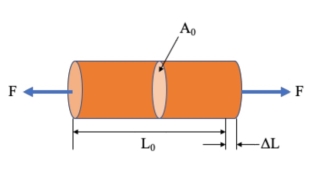
Stress is the force applied to a material, divided by the material’s cross-sectional area.

σ = stress (N/m2, Pa)
F = force (N)
A0 = original cross-sectional area (m2)
Strain is the deformation or displacement of material that results from an applied stress.

ε = strain
L = length after load is applied (mm)
L0 = original length (mm)
Note: A material’s change in length (L – L0) is sometimes represented as δ.
Plane Stress
In a case of plane stress, one direction can be found that is free of normal stress and shear stress. If we place the z-axis in this direction, we must

The generalized Hooke's law equation reduces to

10.2.1 Transformation of Stresses at a Point
It is suitable to neglect the small stress, and in its place of calculating the stress acting on a cubic element inside the material, we can examine the stress acting on a plane.
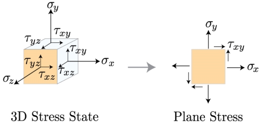
These two states of stress, the 3D stress and plane stress, are frequently discussed in a matrix, or tensor, procedure. As we decrease the dimensionality of the tensor from 3D to 2D, we get free of all the terms that comprise a component in the z direction, such that

Now that we've reduced our state of stress to two dimensions, we can study how to convert the coordinates beside which these stress components act into any coordinate frame we are interested in. Why would we want to do that? Well, take a look at the image below. >
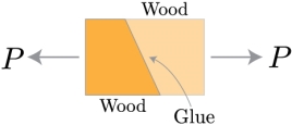
Two parts of wood, cut at an angle, and glued together. The wood is being pulled apart by a tensile force P. How do we distinguish if the glued combined can stand the resultant stress that this force produces?
We need to estimate the normal and shear stresses perpendicular and parallel to the joint. Thus, we need to rotate, or transform, the coordinates linked with the force P to the direction associated with the angle of the glued joint. Then, we can evaluate the stresses along these new directions, x' and y'.
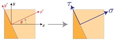
Once we've rotated the coordinate system, we need to convert the forces substitute in the old coordinate frame to this new coordinate frame. That means, we need draw a full free body diagram.
If we take a differential element close the origin of the new coordinate system, we can acquire the forces performing on each surface from the stress times the differential area.
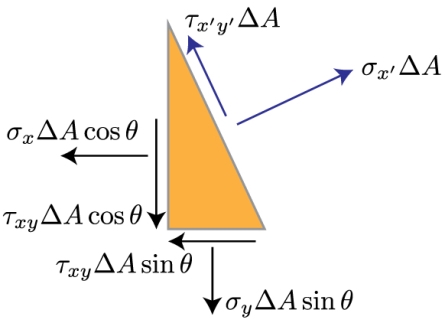
As you'll notice from the free body diagram, most of the forces aren't directing in the directions we're involved in, that is x' and y'. So, we must to break these forces into their components, and sum the resulting forces in the directions of our new coordinate system.
These consequences in a long, but straightforward, calculation given below
We can stop here if we'd like. However, if we make use of a couple trigonometric identities, we can make these equations a bit more friendly looking.
By means of these characteristics, we can get free of all those squared sines and cosines. The final result for the normal and shear stresses in our new coordinate system denoted by theta, which is a counter clockwise rotation from the x axis to the x' axis is given by
10.2.2 Principal Stress & Mohr's Circle
We have just shown that the size of the cut and normal stress will depend on the coordinate system chosen. If you rotate the coordinate system at any angle, the magnitude of these stresses will change.
As can be suspected, certain angles will correspond to the maximum and minimum values of these stresses.
As one way to determine the ends of a function is to differentiate it from the variable of interest and set the resulting equation equal to zero.
Now, we can resolve for by recalling the connection between sines, cosines, and tangents, such that
Included We have included an index p in theta to identify this angle as the plane corresponding to the normal maximum and minimum stresses. These equations have two roots, that is, two theta values will satisfy you.
These two values will be separated by 900 (or 2 * theta will be separated by 1800). One corner will correspond to the maximum normal effort and the other will correspond to the minimum.
We will talk about identifying which one is that short. First, we note that we can repeat this same procedure to determine the angle at which the element will be subject to the maximum and minimum cut:
Now that we have plans where the stress will be maximum and minimum, we need to identify the extent of these main stresses. There are several ways to do this, but the general idea should be familiar to anyone who has seen linear algebra techniques.
Our goal is to diagonalize our flat stress tensor and the resulting eigenvalues will correspond to the extremes of our state of stress.
Objective Our objective in finding the main stresses in an element is to eliminate the dependence of the theta stress transformation equations.
The equations that describe stress transformation are the parametric equations of a circle.
We can remove the theta by squaring both sides and adding them (I took the liberty of transposing the first term on the right side of the equation, which is independent of the theta and corresponds to the average stress).
This calculation looks much worse than it is. Again, we simply transpose the average stress, square both sides and add the equation for normal stress to the equation for shear stress.
Things are pretty good. The second term on the right side of each equation is cancelled. What we are left with are the terms sine square plus cosine square and from our trigonometric identities we remember that this term is equal to zero.
The resulting equation contains the main normal and shear stresses. The main normal stress will occur when the shear stress is zero, which means
The principal shear stress is simply the square root term
An alternative to using these equations for the main stresses is to use a graphical method known as the Circle of Mohr. This involves creating a graph with sigma as abscissa and tau as ordinate and representing the state of stress given. The sign convention is as follows
We draw two points. The normal and shear stress acting on the right side of the plane constitutes a point, and the normal and shear stress on the upper face of the plane constitutes the second point.
These two points are located in a circle. The centre of that circle is the average normal stress. The radius of that circle is the extreme shear stress. The highest sigma value is the first major stress and the smallest sigma value is the second largest stress.
Mohr's Circle:
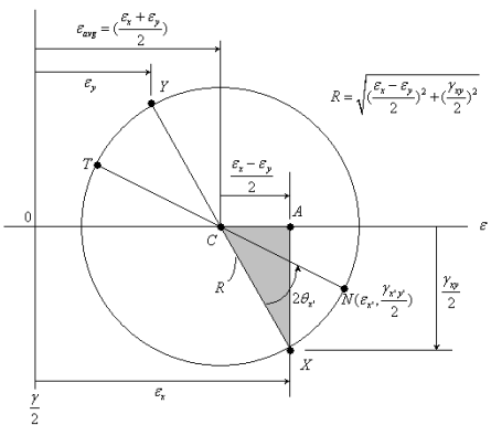
Mohr's circle is not actually a new derived formula, but only a new way of viewing the relationships between normal deformations and shear deformations when the rotation angle changes. To determine the effective equation for the Mohr circle, the deformation transformation equations can be rearranged to provide,
Each side of these equations can be squared and then added together to give Grouping like terms and cancelling other terms gives
Using the trigonometry identity, cos22θ + sin22θ = 1, gives
A displacement field is a displacement vector mapping for all points in a region or body that moves from one state to another. A displacement vector specifies the position of a point or particle with reference to a previous origin or position. For example, a displacement field can be used to describe the effects of deformation on a solid body.
Before considering displacement, it is necessary to define the state before deformation. It is a state in which the coordinates of all points are known and described by the function
If a bar is subjected to a direct load and therefore a stress the bar will modify in length. Strain is therefore calculated of the deformation of the material and is a non dimensional Quantity i.e., it have no units. It is just a ratio of two quantities with the same unit.
Plane Strain
In this case we have a direction along which the extensional strain is zero, and selecting the z axis as that direction, we have E z = 0, and the extensional stress-strain relations may be combined as follows.


Basic Mohr's Circle for Strain:
This is basically an equation of a circle. The circle equation can be better visualized if it is simplified to
This circular equation is drawn on the left using r and εave. An advantage of the Mohr circle is that the main deformations, ε1, ε2 and the maximum shear strain, (γmax / 2), are easily identifiable on the circle without further calculations.
A displacement field is a displacement vector mapping for all points in a region or body that moves from one state to another. A displacement vector specifies the position of a point or particle with reference to a previous origin or position. For example, a displacement field can be used to describe the effects of deformation on a solid body.
Before considering displacement, it is necessary to define the state before deformation. It is a state in which the coordinates of all points are known and described by the function:
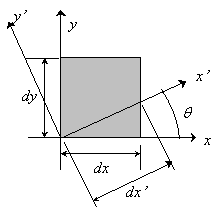
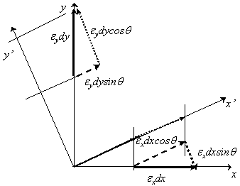
Strain-Transformation equations:
Strain-Transformation equations are created on the geometry of the deformation of deformable bodies (comprising some small-angle approximations).
External strain, or normal strain, is defined as a ratio of aentire elongation ∆L to an original length L.
 Shear strain is defined as a change in angle between two initially perpendicular line segments that intersect at a point. When
 , angle the sheared line creates with its original orientation, equals 90 degrees, the shear strain is infinite.

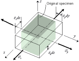
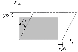
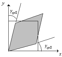
Normal and Shear Strain
The extensional strains and
and are shown by observing the change in length of short, mutually orthogonal line segments
 and
and ; and the shear strains
 and
and are shown by the variations in right angles that originally be between these lines.
General Equations


Principal Strains
In-Plane Principal Strains:
In-Plane Principal Directions:

Maximum Shear Strains
Maximum In-Plane Shear Strains:
In-Plane Shear Directions:

Mohr's circle for two-dimensional Strain
Similar to the stress-transformation equations, the strain-transformation equations can be simplified but presenting the double-angle trigonometric characteristics.
This yields

 ---2
---2
So


Calculation of a circle in the plane with center at
 and radius R, with the angle
 existence a parameter is

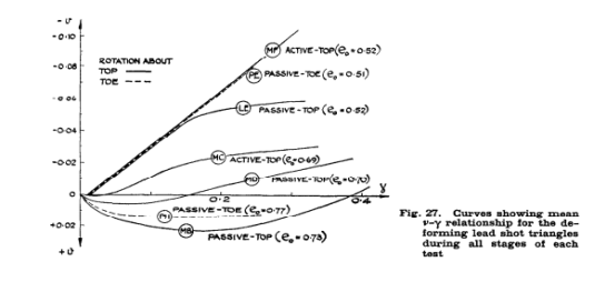
This curve, for a test in which the maximum normal stress on the wall never exceeded 1 lb/sq.in., is identical to that in test LE when this stress was 23 lb/sq.in. And also to that in test PE when this stress rose to 40 lb/sq.in. It would therefore seem reasonable to assume for these tests on dense sand that, for values of γ between 0.01 and 0.15 and for all stress levels, the sand dilated at a constant rate  (given by the slopes of these curves) corresponding to a value of v = 20.2o. The second additional curve is for test MC which is also for an active test with the wall rotating about its top away from moderately loose sand (eo = 0.69) with the normal stress level never exceeding 1 lb/sq.in. When this is compared with the corresponding passive test MD (eo = 0.70), in which the normal stress level rose to 6 lb/sq.in., it is evident that stress level has a significant effect on the dilation behaviour of moderately loose sand. The third additional curve in Fig.27 refers to a passive test MB with the wall rotating about its top into a loose sand (eo = 0.73) in which the normal stress level rose to about 4.5 lb/sq.in. When this is compared with the curve for test PH with the wall rotating about its toe into an even looser sand (eo = 0.77) and in which the normal stress rose to the same value of 4.5 lb/sq.in., it is also apparent that initial voids ratio has a profound effect on the dilation behaviour of loose sand. The curves in Fig. 27 becomes important when attempting to relate stresses and strains in the soil mass.
Categorization of the mechanical conduct of an unidentified material approximately for all time begins with performing a tensile experiment. A stepwise transform in the axial stress σ may be arranged and the strain ε of the tensile bar can be calculated and plotted as a function of time. From these plots important conclusion can be drawn relating to the material behavior. For elastic material activities the strain follows the stress instantly and become zero after stress release. For elastoplastic material performance the strain also follows the stress instantly, but there is permanent deformation after stress release. When the material is viscoelastic the strain shows time prompt reply on a stress step, which indicate a time dependent performance. When time dependent performance is accompanying by permanent deformation, the performance is referred to as viscoplastic.
THREE-DIMENSIONAL MATERIAL ANISOTROPY
For a three-dimensional elastic anisotropic body (Fig. 6.1), the general Hooke's law is stated as
 ij = 1,2,3) (6.1)
Where  besides
  are the stress and
 strain tensors, correspondingly, and are the elastic constants. Here the indices i, j, k and l can assume values of 1, 2 and 3. This suggests that there may exist 34 = 81 independent elastic constants. Though, it is known from the theory of elasticity, that both stress tensor
  and strain tensor
  are symmetric. As =
And as  (6.2)
(6.2)
Thus,  (6.3)
(6.3)
This effects in reduction of likely independent elastic constants to thirty-six.
Additional, if there exists a strain energy U such that
 (6.4)
(6.4)
With the property that  , then
 (6.5)
(6.5)
Equation 6.5 in combination with Eq. 6.3 lastly reduce the total number of independent elastic constants from thirty-six to twenty-one only. Such an anisotropic material with twenty-one independent elastic constants is called as triclinic. Now, using the following contracted single index notations
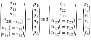 (6.6)
(6.6)
The constitutive relations for the general case of material anisotropy are specified as
 (6.7)
(6.7)
Or, ; i, j = 1, 2, …,6 (6.8)
Now, [  ] is the elastic constant matrix.
Equally, {  } = [Sij] {
 }; i, j =1, 2,�..,6 (6.9)
Where [Sij] is the submission matrix.
Note that
[Sij] = [Cij]-1 (6.10)
Similarly, [Cij ] =[ Cji ] and [Sij] = [Sji] due to symmetry.
We refer to the proportionality constant between stress and tension as the elastic modulus. But why do we call it that? What does it mean that an object is elastic and how can we describe its behaviour?
Elasticity is the tendency of solid and material objects to return to their original shape after the external forces (load) that cause deformation are removed. An object is elastic when it returns to its original size and shape when the load is no longer present. The physical reasons for elastic behaviour vary between materials and depend on the microscopic structure of the material. For example, the elasticity of polymers and gums is caused by the elongation of the polymer chains under an applied force. On the contrary, the elasticity of the metals is caused by the change in size and by the remodelling of the crystalline cells of the networks (which are the material structures of the metals) under the action of externally applied forces.
The two parameters that define the elasticity of a material remain its elastic modulus and its elastic limit. A high elastic modulus is typical for materials that are difficult to deform; in other words, materials that require a high load to obtain significant voltage. An example is a steel band. A low elastic modulus is typical for materials that deform easily under load; for example, an elastic band. If the stress under a load is too high, when the load is removed, the material no longer returns to its original shape and size, but relaxes in a different shape and size: the material is permanently deformed. The elastic limit is the tension value beyond which the material no longer behaves elastically but deforms permanently.
Our perception of an elastic material depends both on its elastic limit and on its elastic modulus. For example, all tires are characterized by a low elastic modulus and a high elastic limit; therefore, it is easy to stretch them and the elongation is remarkably large. Of the materials with identical elastic limits, the most elastic is the one with the lowest elastic modulus.
When the load increases from zero, the resulting stress is directly proportional to the stress, but only when the stress does not exceed a limit value. For stress values within this linear limit, we can describe the elastic behaviour in analogy with Hooke's law for a spring. According to Hooke's law, the elongation value of a spring under an applied force is directly proportional to the amount of force. On the contrary, the response force of the spring to an applied elongation is directly proportional to the elongation.
Similarly, the deformation of a material under a load is directly proportional to the load and, on the contrary, the resulting stress is directly proportional to the stress. The linearity limit (or proportionality limit) is the highest voltage value beyond which the voltage is no longer proportional to the voltage. Beyond the linearity limit, the relationship between stress and tension is no longer linear. When the stress becomes greater than the linearity limit but still within the elastic limit, the behaviour remains elastic, but the relationship between stress and tension becomes nonlinear.
For stresses beyond the elastic limit, a material exhibits a plastic behaviour. This means that the material irreversibly deforms and does not return to its original shape and size, even when the load is removed. When the tension gradually increases beyond the elastic limit, the material undergoes a plastic deformation. Rubber-like materials show an increase in tension as tension increases, which means that they become more difficult to stretch and eventually reach a breaking point where they break.
Ductile materials such as metals show a gradual reduction of stress with increasing stress, which means that they become easier to deform when the stress deformation values approach the breaking point. The microscopic mechanisms responsible for plasticity of materials are different for different materials.
We can trace the relationship between stress and tension on a stress-strain diagram. Each material has its own characteristic stress deformation curve. Typical stress-strain diagram for a ductile metal under load. In this figure, deformation is a fractional stretch (not drawn to scale). When the load gradually increases, the linear behaviour (red line) that begins at the non-load point (the origin) ends at the linearity limit at point H.
For a higher load it increases beyond the H point, the voltage relationship - non-linear deformation, but still elastic. In the figure, this nonlinear region is seen between the points H and E. The increasing loads bring the stress to the elastic limit E, where the elastic behaviour ends and the plastic deformation begins. In addition to the yield strength, when the load is removed, for example in P, the material relaxes in a new shape and size along the green line. This means that the material is permanently deformed and does not return to its initial shape and size when the tension becomes zero.
The material undergoes plastic deformation for loads large enough to cause the stress to overcome the yield strength on E. The material continues to be deformed plastically until the stress reaches the fracture point (breaking point). Beyond the fracture point, we no longer have a sample of material, so the diagram ends at the fracture point. To complete this qualitative description, it should be said that linear, elastic and plastic limits indicate a range of values rather than an acute point.
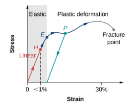
Figure: Typical stress-strain graph for a metal under load: the graph ends at the fracture point. The arrows show the direction of the changes under increasing load. The points H and E are the limits of linearity and elasticity, respectively. Between points H and E, the behavior is not linear. The green line from P illustrates the response of the metal when the load is removed. Permanent deformation has a deformation value at the point where the green line intersects the horizontal axis.
The stress value at the fracture point is called breaking stress (or final stress). Materials with similar elastic properties, such as two metals, can have very different breaking stresses. For example, the final stress for aluminum is 2.2 x 10⁸ Pa and for steel it can reach 20.0 x 10⁸ Pa, depending on the type of steel. We can make a quick estimate, based on equation, that for bars with a cross-sectional area of 1 inch, the breaking load for an aluminum rod is 3.2 x 10⁴ lbs and the load breaking point for a steel bar is about nine times larger

The general Hooke's Law can be used to expect the deformations produced in a specified material by an arbitrary grouping of stresses.
The linear relationship amid stress and strain relates for

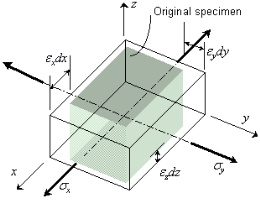


It's Young's modulus
n is the Poisson ratio
Generalized Hooke's law also reveals that tension can exist without stress. For example, if the member is experiencing a load in the y direction (which in turn causes stress in the y direction), Hooke's Law shows that the stress in the x direction is not equal to zero. This is because when the material is pulled out through the y plane, the material in the x plane moves inward to fill the void once occupied, just like an elastic band becomes thinner when you try to separate it. In this situation, the x plane does not have external forces that act on them, but undergo a change in length. Therefore, it is valid to say that voltage exists without voltage on the x plane.
Thermal expansion
Through a change in temperature ΔT, from an ambient temperature, a piece of material will change in volume — it obtains a thermal strain.
A simple model for how this thermal strain ϵth varies with the change in temperature ΔT is
ϵth=αΔT(1)(1)ϵth=αΔT
Where α [1/∘C] is a material parameter entitled the coefficient of thermal expansion.
During a grouping of mechanical and thermal load (change in temperature), we get the total (noticeable) strain as the sum of mechanical and thermal strain.
ϵσ=ϵmech+ϵth=σE+αΔT⇒=E(ϵ–αΔT)(2)(3)(2)ϵ=ϵmech+ϵth=σE+αΔT⇒(3)σ=E(ϵ–αΔT)
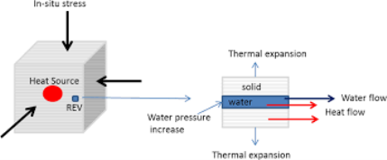
Only mechanical strains give rise to stresses.
For example, if the material only experiences thermal strain (the total strain), then the stress converts zero:
ϵ=ϵth⇒σ=E(ϵth–ϵth)=0(4)(4)ϵ=ϵth⇒σ=E(ϵth–ϵth)=0
Thermal deformation:
The deformation of a bar with length L is obtained as the integral of the strain along the bar
δth=∫Lϵthdx=∫Lα ΔTdx(5)δth=∫Lϵthdx=∫Lα ΔTdx
A common case is having a bar with a homogenious material and supposing a constant change in temperature along the whole bar. The thermal deformation can then be written
δth=α ΔT∫Ldx=α L ΔT(6)
|
|  |  |
K | V |  |  |
K |  |  |  |
V |  |  |  |
10.12.1 Axial force
Itis the force in the radius that acts parallel to the longitudinal axis.
10.12.2 Shear force
The cutting force is the force on the radius that acts perpendicularly to its longitudinal axis (x). For design purposes, the ability of the beam to resist shear force is more important than its ability to resist axial force.
Below is a drawing of a simply supported beam of length L under uniform load, q:

This beam has the following support reactions:
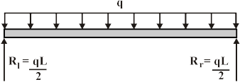
Where Rl and R rare the responses at the left and right ends of the beam, correspondingly.
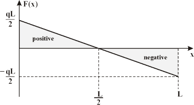
The shear forces at the ends of the beam are equivalent to the vertical forces of the support responses. The shear force F(x) at some other point x on the beam can be establish by using the succeeding equation.

Here x is the distance from the left side of the beam.
Shear force diagrams are only plots of the shear force (on the y-axis) versus the position of various points along the beam (on the x-axis). Thus, the succeeding is the generalized shear force diagram for the beam shown above.
10.12.3 The bending moment
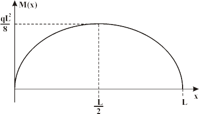
At any point along the beam is equivalent to the area in the shear force diagram up to that point. (Annotation: For a simply-supported beam, the bending moment at the ends will constantly be equal to zero.)
To determine the bending moment the beam must be fragmented up into two sections:
(a) 1stfrom x = 0 to x = L/2 and
(b) 2ndfrom x = L/2 to x = L.
The bending moment M(x) at any point x along the beam can be create by using the following calculations:

Bending moment diagrams are just plots of the bending moment (on the y-axis) versus the position of various points along the beam (on the x-axis). Therefore, the resulting is the general bending moment diagram for the beam shown above.
10.13.1 Torsion of Circular Shafts
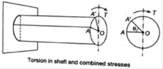
Torsion state that twisting a structural Member when it is loaded by couple that Produces rotation around longitudinal axis.
If  stand the intensity of shear stress, on slightly layer at a distance r from the centre of shaft, now

Sign Convention:
Sign convention of torque can be described by right hand thumb rule. A positive torque is that in which here is tightening effect of nut going on the bolt. From either side of the cross-section. If torque is useful in the direction of right-hand fingers than right hand thumbs direction signifies movement of the nut.
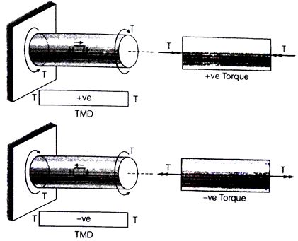
TMD = Torsion moment diagram
T = Torque
Rate of twist:

Total angle of twist:
Where, T = Torque,
J = Polar moment of inertia
G = Modulus of rigidity,
θ = Angle of twist
L = Length of shaft,
GJ = Torsional rigidity
 Torsional stiffness;
 Torsional flexibility
 Axial stiffness;
 Axial flexibility
Moment of Inertia About polar Axis:
For solid circular shaft:
For hollow circular shaft: 
Power Transmitted in the Shaft
Power transmitted by shaft:

Where, N = Rotation per minute.
Compound Shaft
An established type of compound coupling for linking in series and parallel are specified below
Series connection: Series linking of compound shaft as shown in figure. Due to series connection the torque on shaft 1stwill be equal to shaft 2ndand the entire angular deformation will be equivalent to the sum of deformation of 1st shaft and 2nd shaft.
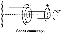


Therefore,
Where,
θ1 = Angular deformation of 1st shaft
θ2 = Angular deformation of 2nd shaft
Parallel connection: Parallel connection of compound shaft as revealed in figure. Due to parallel connection of compound shaft the entire torque will be equivalent to the sum of torque of shaft 1stand torque of shaft 2ndand the deflection will be similar in equally the shafts.


Therefore,

Strain energy (U) stored into shaft due to torsion:
 . Volume of shaft
G = Shear modulus, T = Torque, J = Moment of inertia around polar axis
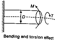
Effect of Pure Bending on Shaft
The result of pure bending on shaft can be defined by the relative for the shaft,
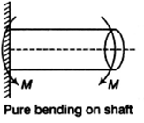

Where, σ = Principal stress
D = Diameter of shaft
M = Bending moment
Effect of Pure Torsion on Shaft
It can be calculated by the formula, which are given below
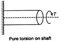

Where, τ = Torsion
D = Diameter of shaft
Combined effect of bending and torsion
Principal stress 
Maximum shear stress 
Equivalent bending moment:
Equivalent torque 
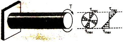
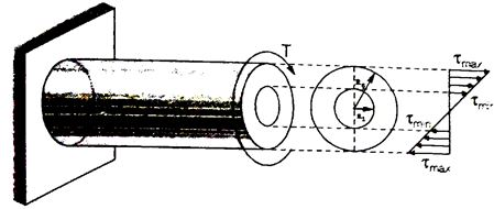
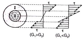
Shear Stress Distribution:
Solid Circulation Section:
Hollow Circulation Section
Composite Circular Section
Thin Tubular section: In view of small thickness shear stress is supposed to be constant
10.13.2 Torsion of thin-walled circular tubes
Introduction:
The simplest torsion problematic is that of the twisting of an even thin circular tube.
Description:
The tube revealed in Figure is of thickness f, and the mean radius of the wall is r, L is the length of the tube.
Shearing stresses T are useful around the circumference of the tube at each end and in differing directions.
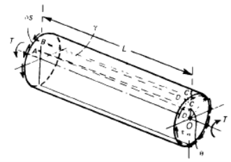
Figure: Torsion of a thin-walled circular tube.
If the stresses T are uniform round the boundary, the total torque Tat individually end of the tube is

Therefore, the shearing stress round the Circumference due to an applied torque Tis

We study next the strains produced by these shearing stresses. We note firstly that balancing shearing stresses are set up in the wall parallel to the longitudinal axis of the tube.
If δs is a small length of the boundary then an element of the wall ABCD, is in a state of pure shearing stress. If the remote end of the tube is theoretical not to twist, then the longitudinal element ABCD is distorted into the parallelogram ABC'D', Figure the angle of shearing strain existence

If the material is elastic, and requires a shearing (or rigidity) modulus G. However, if is the angle of twist of the near end of the tube we must

Hence

It is occasionally more convenient to define the twist of the tube as the rate of change of twist per unit length; this is given by (θ/L)

- The discussion, up to now of the rays in pure flexion, has been limited to the rays that are straight before the application of the moment. This is no longer true in this section since the beams are initially curved. Curved beams are found at various points in aerospace structures. For example, the frames or rings on the fuselage of an airplane are basically curved beams. To analyze curved rays, we need to clarify the assumptions and restrictions of the analysis.
- Requirements:
- The cross sections of the curved beam remain flat after applying the moment.
- Yup. The material used is linearly elastic.
- Restrictions:
- The beam must have a uniform cross section along its length.
- The radius segment in question has a constant radius of curvature C.
- The cross section of the beam must have at least one axis of symmetry so that the product of inertia is zero.
- The bending moment is applied perpendicular to the radius of curvature of the radius.
- Flexural stresses must remain below the elastic limit.
- In general, for beams that have radii of curvature much longer than their depth, the elastic bending formula provides fairly reasonable results for bending stresses. However, for a more accurate calculation of the stresses, especially when the radius of curvature is of the same order of magnitude as the depth of the radius, then we must use Winkler's method of analysis.
- • On curved beams, the assumption that flat sections remain flat after loading is still valid. However, since the length of the beam varies from its upper surface
- To the lowest surface, the strain variation is no longer linear, instead it is hyperbolic.
- These two equations show that stress and strain vary hyperbolically alongside the cross section.


- Dissimilar in the instance of straight elastic beams, the neutral axis does not pass through the centroid of the cross section. Somewhat, it is located somewhere between the centroid of the cross section and the center of curvature of the beam. Its precise location can be firm by the equation given below.

- The differential area 'dA' is taken in such a way that creates the evolution of the integral in the denominator rightly easy. The closed form calculation for 'R' for some simple cross-sectional shapes are given in the figure below.
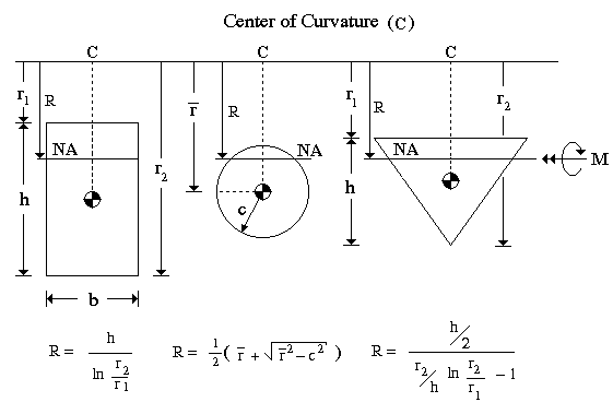
- The radius of curvature, stately from the center of curvature to the centroid of the cross section, is determined by

- By means of the moment equilibrium calculation along with the Hooke's law, the bending stress in positions of moment is gotten as
 where
where 
- Or

- The sign related with the moment is positive if the moment tends to increase the curvature. It is negative if it inclines to reduction the curvature, or flatten the curved beam.
- Strain is determined from Hooke's law as

- Though the stress and strain differences alongside the cross section of the curved beam are hyperbolic, Hooke's law is still valid since the material is linearly elastic, i.e., stress-strain relation is linear.

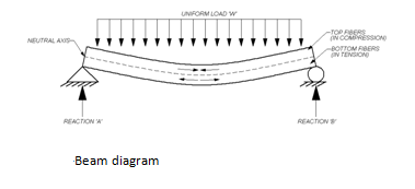
When a limb similar to the one in the figure is loaded, a flexion effort (or flexion effort) will occur. Flexion stress is a more specific type of normal stress. When a beam undergoes a load such as that shown in Figure 1, the upper fibers of the beam undergo normal compression stress. The voltage in the horizontal plane of the neutral is zero. The lower fibers of the bundle undergo normal tension. Therefore, it can be concluded that the bending stress value will vary linearly with the distance from the neutral axis.


Y=vertical distance away from the neutral axis
I=moment of inertia around the neutral axis
Manipulative the maximum bending stress is critical for defining the competence of beams, rafters, joists, etc.
Normal stress is the result of the load applied perpendicularly to a limb. However, shear stress occurs when a parallel load is applied to an area. If we look again at figure one, you can see that the bending and shear stresses will develop. Similar to the bending stress, the shear stress will vary in the cross-sectional area.


Manipulative the maximum shear stress is too crucial for shaping the adequacy of beams, rafters, joists, etc.
Final Considerations
Normal Stress By executing any type of beam design using structural design software, the entire stress calculation process will be greatly facilitated. There are several technical design software packages available for beams, columns or foundations. StruCalc, Enercalc, Risa and BeamChek will take into account normal and shear stresses during the execution of any type of beam design: Ss is the result of the load applied perpendicular to an element. However, shear stress occurs when a parallel load is applied to an area. If we look again at figure one, you can see that the bending and shear stresses will develop. Similar to the bending stress, the shear stress will vary in the cross-sectional area.
Under combination of
Direct Stress
σd= P/A
Here P = axial thrust, A = area of cross-section
Bending Stress
σb= My/l
Here M = bending moment, y- distance of fibre after neutral axis,
I = moment of inertia.
Shear stresses
Τ= Tr/J
Here T = torque, r = radius of shaft, J = polar moment of inertia.
Combined Stress is:
- Equivalent Torsional Moment:
The equivalent torsional moment is described as the torsional moment, which when performing alone, will produce the same torsional shear stress in the shaft as under the joint act of bending moment (Mb) and torsional moment (Mt)

- Equivalent Bending Moment:
The equivalent Bending moment is different as the bending moment, which when performance only, will produce the same bending stresses (tensile and compressive) in the shaft as below the joint action of bending moment (Mb) and torsional moment (Mt)

Strain Energy Formula
Strain energy is definite as the energy stored in a body due to deformation. The strain energy per unit volume is recognized as strain energy density and the area under the stress-strain curve to the point of deformation. When the functional force is released, the whole system proceeds to its original shape. It is typically denoted by U.
The strain energy formula is given as,
U = Fδ / 2
Here,
δ = compression,
F = force applied.
When stress σ is relative to strain ϵ, the strain energy formula is assumed by,

Here,
σ = stress
 = strain
V = volume of body
Concerning young’s modulus E, the strain energy formula is assumed as,
U = σ2 / 2E × V.
Where,
σ = stress,
E = young’s modulus,
V = volume of body.
Although tightening changes the position of the elastic limit, both effects can be treated separately. The yield point is measured fixed in its first position and the curing effects are added gradually when desired.
In literature there is a variation of criteria for the execution of the material found. The main task is to derive, from the tension tensor, a criterion that triggers the performance for different types of materials. For example, in fragile materials, a good criterion is measured according to which the performance occurs, in detail, the fracture of fragile materials instead of lowering, when the main main stress exceeds an experimentally established threshold. However, for ductile materials, the maximum shear stress functions are a more appropriate criterion. Furthermore, anisotropic materials require a completely different treatment, which considers the directional dependence of the material properties.
The materials used in the semiconductor industry are generally ductile. For these types of materials, there are two theories most frequently implemented: the Tresca theory (or maximum shear stress) and von Mises theory (or distortion energy theory).
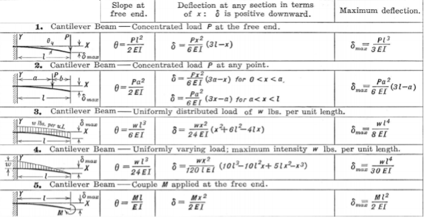
When two bearings are used on a simply maintained beam, as is classically the case with round shaft guides, the useful load is split between the two bearings, and maximum deflection happens in two places: at the location of individually bearing when the bearing meeting (sometimes referred to as a carriage or table) is at the middle of the shaft.
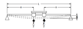
Image credit: Thomson Linear
The beam deflection calculation for this condition is:

Over, we must add the deflection due to the beam’s own weight, plus the deflection due to the functional load, to get an entire deflection of:

Strain energy stored due to axial load

Where, P = Axial load
Dx = Elemental length
AE = Axial rigidity
Strain energy stored due to bending

Where, MX = Bending moment at section x-x
Ds = Elemental length
El = Flexural rigidity
Or E = Modulus of elasticity
l = Moment of inertia
Strain energy stored due to shear

Where, q = Shear stress
G = Modulus of rigidity
Dv = Elemental volume
Strain energy stored due to shear force

Where, AS = Area of shear
S = Shear force
G = Modulus of rigidity
Ds = Elemental length
Strain energy stored due to torsion

Where, T = Torque acting on circular bar
Dx = Elemental length
G = Modulus of rigidity
lP = Polar moment of inertia
Strain energy kept in terms of maximum shear stress

Where,  Maximum shear stress at the surface of rod in twisting.
G = Modulus of rigidity
V = Volume
Strain energy kept in hollow circular shaft is,

Where, D = External diameter of hollow circular shafts
d = Internal diameter of hollow circular shaft
 Maximum shear stress
Castigliano’s Method
This method deals with displacements with respect to strain energy (Strain energy is also called potential energy, also called Internal energy). It is really the strain energy method of finding deflection. Strain energy is recoverable as mechanical energy or mechanical work. Displacement in Castigliano’s method means
- Extension under an axial tensile force, δL= PL/AE
- Contraction under an axial compressive force, δL= — PL/AE
- Deflection due to Bending Moment and shear force, y= δM + δV
- Angle of twist due torque (torsional moment), ϴ = TL/GJ
- Extension in a spring due to a force, δ =W/k
- Contraction in a spring due to a force, δ =W/k and etc.
Castigliano's first Theorem

Where, U = Total strain energy
Δ = Displacement in the way of force P.
θ = Rotation in the way of moment M.
Castigliano’s Second Theorem

CASTIGLIANO’S METHOD
This Method determines the displacement in a linearly elastic system (loaded bar, beam, shaft or structure) at any point by using the partial derivatives of the strain energy. There are two Castigliano’s theorems
(i) Castigliano’s First Theorem OR Castigliano’s Force Finding Method or Castigliano’s Force Theorem
Determines the force at a certain point of known displacement ‘δi’ within elastic limits. Express strain energy of an elastic structure as a function of generalized displacement δi; then find the partial derivative of the strain energy with respect to generalized displacement, δi. This partial derivative gives the force Fi. In the mathematical form, it is given as
Fi = ∂U/∂δi
Where U is the total strain energy due to the forces/moments/torques etc.
δi is the displacement at any point ‘i’
Fi is the force at the point ‘i’
(ii) Castigliano’s Second Theorem or Castigliano’s Displacement Finding Method or Castigliano’s Displacement Theorem
It determines Displacement at a point of the loaded beam by using the partial derivatives of the strain energy with respect to the force acting at that location. If the Displacement is positive, then it is in the direction of the force and vice versa. In the mathematical form, it is given as
δi = ∂U/∂Fi
Where
δi is the displacement of the point under the force Fi in the direction of Fi
U is the total strain energy
COR: Castigliano’s theorem
It can also determine the slope at a point of the loaded beam by using the partial derivatives of the strain energy with respect to the bending moment acting at that location. In the mathematical form, it is given as
θi = ∂U/∂Mi
Where U is the total strain energy,
θi is the slope (rotational displacement in radians) of the moment Mi in the direction of M (Clockwise or anticlockwise)
NOTE: THIS METHOD IS VERY USEFUL FOR OBTAINING THE DEFLECTION OF A POINT WHERE THERE IS NO FORCE OR NO MOMENT. IN THIS CASE A FORCE/ MOMENT (FICTITIOUS) IS ASSUMED TO ACT AND THEN MADE ZERO AT THAT POINT IN THE ANALYSIS AFTER FINDING THE DERIVATIVE OF THE STRAIN ENERGY WITH RESPECT TO THE FORCE.
MEANING OF GENERALIZED DISPLACEMENTS
1. In Simple Tension
Extension in tension δL= PL/AE
Strain energy = Average Force x δL = (F/2) (PL/AE) = =F2L/2EA
2. In Simple Compression
Extension in compression δL= PL/AE
Strain energy = Fav δL = (F/2) (PL/AE) = =F2L/2EA
3. In Simple Bending
Strain energy = Average Bending moment x deflection
= (M/2) (ML/EI) = M2L/2EI
4. Angle of twist in simple torsion
Strain energy= Average torque x displacement =average torque x angle of twist
= (T/2) (TL/GJ) = T2 L/2GJ
STRAIN ENERGY IN A MEMBER FOR ANY ONE TYPE OF LOADING
Sr. No. Type of loading Strain energy with variable loading Strain energy with constant loading
- Axial load (tensile or compressive), FU =∫ F2dx/2EAU =F2L/2EA
- Bending Moment, MU = ∫ M2dx/2EAU =M2L/2EI
- Torque TU = ∫ T2dx/2GJU =T2L/2GJ
- Direct shear force, FU = ∫ F2dx/2GAU =F2L/2GA
- Transverse shear force, VU = ∫ V2dx/2GAU =K V2L/2GA
INTEGRATION LIMITS ARE FROM 0 to L in the tabular equations.
Where K is a correction factor depending upon the shape of the area
Rectangular section K =1.2
Solid circular section K =1.11
Thin walled tube K =2.0
PROCEDURE FOR APPLICATION OF CASTIGLIANO’S THEOREM
a) To determine a deflection yf in the direction of a real force Ff or fictitious force Ff
- Prepare an expression for the total strain energy.
- Obtain the linear deflection yf from the relationship yf = ∂U /∂Ff
- If the force is fictitious, set Ff = 0 and solve the resulting equation)
- To determine the slope (an angular displacement) θf in the direction of a fictitious moment Mf
- Write the expression for the total strain energy.
- Determine the angular deflection from the relationship θf= ∂U /∂Mf
- If the moment is fictitious, then set Mf = 0 and solve the resulting equation.
It was Hooke's observation that for linearly-elastic, isotropic materials, normal strain is proportional to normal stress with Young's modulus or the elastic modulus, E, as the constant of proportionality. For a stress along the x direction

And Poisson observed that an extension along x is accompanied by contractions in the orthogonal directions y and z.


Where Poisson's ratio is the constant of proportionality. If a normal stress in the y direction is added to this, it would cause an extension in the y direction and proportional contractions in the x and z directions. For small deformation we can superpose the results.


Adding a third stress component in the z direction and rearranging terms gives generalized Hooke’s law for the normal components of stress and strain.


The shear strains are uncoupled from the normal strains and from each other for an isotropic material.

Here G is the shear modulus for the material, but only two elastic constants are needed to characterize an isotropic elastic material. Thus, the shear modulus can expressed in terms of E and G can be eliminated.

In the three-dimensional case there are six stress and six strain components. Referenced to a Cartesian coordinate system, x, y, z, the stress and strain vectors are written as follows.

The relationships between strain and stress can be written as

Where C is the compliance matrix of elastic constants relating strain and stress. Using the notations above.
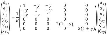
The inverse of this relationship is also of interest, that is, stresses written in terms of strains. Symbolically

Where E = C-1 is a matrix of elastic constants relating stresses to strains. Inverting the compliance relation gives the stress-strain relation for an isotropic material with six stress and strain components as follows.

There are three significant sub-cases of the overall 3D stress/strain state that happen often sufficient to be recognised. These are a state of plane stress, a state of plane strain, and a case involving axisymmetric geometry and loading which causes axisymmetric stresses and strains. Some simplification of the generalized Hooke's laws can be realized in each case.
References:
1. An Introduction to The Mechanics of Solids, 2nd Ed. With Si Units — Sh Crandall, Nc Dahl & Tj Lardner
2. Engineering Mechanics: Statics, 7th Ed. — Jl Meriam
3. Engineering Mechanics of Solids — Ep Popov