UNIT - 2
Laser and Optic Fibre
- Laser is the acronym for light amplification by stimulated emission of radiation.
- A laser is created when electrons in atoms such as special glasses, crystals, or gases absorb energy from an electrical current or another laser and become “excited.”
- The excited electrons move from a lower-energy orbit to a higher-energy orbit around the atom’s nucleus.
- photons (particles of light).
- These photons are all at the same wavelength and are “coherent,” meaning the crests and troughs of the light waves are all in lockstep.
- In contrast, ordinary visible light comprises multiple wavelengths and is not coherent.
- Laser light is different from normal light .
- First, its light contains only one wavelength (one specific color). The particular wavelength of light is determined by the amount of energy released when the excited electron drops to a lower orbit.
- Second, laser light is directional. The laser generates a very tight beam, the flashlight produces light that diffuses.
- Because laser light is coherent, it stays focused for vast distances, even to the moon and back.
- Characteristics
Laser light has four unique characteristics that differentiate it from ordinary light these include:
- Coherence
- Directionality
- Monochromatic
- High intensity
Coherence
- The visible light is emitted when excited electrons (electrons in higher energy level) jumped into the lower energy level (ground state).
- The process of electrons moving from higher energy level to lower energy level or vice-versa is called transition.
- In ordinary light sources such as lamp, sodium lamp and torch light, the electron transition occurs naturally.
- That is the electron transition in ordinary light sources is random in time. The photons emitted from ordinary light sources have different energies, frequencies, wavelengths, or colors.
- Hence, the light waves of ordinary light sources have many wavelengths. Therefore, photons emitted by an ordinary light source are out of phase.
|
Figure 1- Incoherent light
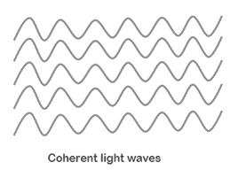
In laser, electron transition occurs in specific time. All the photons emitted in laser have the same energy, frequency, or wavelength.
- Hence, the light waves of laser light have single wavelength or color. Therefore, the wavelengths of the laser light are in phase in space and time.
- In laser, a technique called stimulated emission is used to produce light.
|
Figure 2. Coherent light waves
Thus, light generated by laser is highly coherent. Because of this coherence, a large amount of power can be concentrated in a narrow space.
Directionality
- In conventional light sources such as lamp, sodium lamp and torchlight, the photons will travel in random direction. Therefore, these light sources emit light in all directions.
- All photons travel in same direction therefore, laser emits light only in one direction. This is called directionality of laser light.
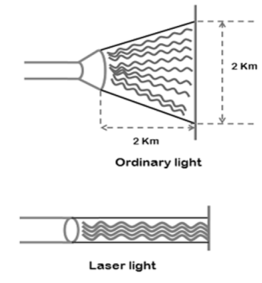
- The width of a laser beam is extremely narrow. Hence, a laser beam can travel to long distances without spreading.
|
Figure 3: Direction of light
If an ordinary light travels a distance of 2 km, it spreads to about 2 km in diameter. On the other hand, if a laser light travels a distance of 2 km, it spreads to a diameter less than 2 cm.
Monochromatic
- Monochromatic light means a light containing a single color or wavelength. The photons emitted from ordinary light sources have different energies, frequencies, wavelengths, or colors.
- Hence, the light waves of ordinary light sources have many wavelengths or colors. Therefore, ordinary light is a mixture of waves having different frequencies or wavelengths.
- In laser all the emitted photons have the same energy, frequency, or wavelength. Hence, the light waves of laser have single wavelength or color.
- Therefore, laser light covers a very narrow range of frequencies or wavelengths.
High Intensity
The intensity of a wave is the energy per unit time flowing through a unit normal area. In an ordinary light source, the light spreads out uniformly in all directions.
In laser, the light spreads in small region of space and in a small wavelength range. Hence, laser light has greater intensity when compared to the ordinary light.
Single Hetero junction Laser:
A p-n junction is made of different materials in two regions that is n-type and p-type known as hetrojunction.
Principle:
When the PN junction doide is forward biased the electrons flow from n-region and holes from p-region recombine with each other at the junction. During this process light is released from certain specified direct band gap semiconductors.
Construction:
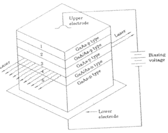
This laser consists of five layers as shown in the figure.
|
Figure 4: Single Hetro-junction laser
- A layer of Ga-As p – type (3rd layer) will act as the active region. This layer is sand witched between two layers having wider band gap with GaAlAs-p – type (2nd layer) and GaAlAs-n-type (4th layer).
- The end faces of the junctions of 3rd and 4th layer are well polished and parallel to each other. They act as an optical resonator.
Working:
- When the PN junction is forward biased, the electrons and holes are injected into the junction region.
- The region around the junction contains large number of electrons in the conduction band and holes in the valence band.
- Thus, the population inversion is obtained . At this stage, some of the injected charge carriers recombines and produce radiation in the form of light.
|
Figure 5. Forward biased junction
- When the forward biased voltage is increased, more and more light photons are emitted and the light intensity is more. These photons can trigger a chain of stimulated recombination’s resulting in the release of photons in phase.
- The photons moving at the plane of the junction travels back and forth by reflection between two sides and grow its strength.
- A coherent beam of laser having wavelength nearly 8000 A emerge out from the junction region.
Co2 Molecular gas laser:
- The first molecular gas laser was developed by Indian born American scientist Prof.C.K.N. Pillai.
- Four level laser which operates at 10.6 μm in the far IR region.
- Efficient laser.
Energy states of CO2 molecules
The carbon dioxide molecule has carbon atom at the centre with two oxygen atoms attached, one at both sides. Such a molecule exhibits three independent modes of vibrations. They are
a) Symmetric stretching mode.
b) Bending mode
c) Asymmetric stretching mode.
Symmetric stretching mode:
In this mode of vibration, carbon atoms are at rest and both oxygen atoms vibrate simultaneously along the axis of the molecule departing or approaching the fixed carbon atoms.
|
Figure 6 : Symmetric stretching mode
Bending mode:
In this mode of vibration, the oxygen and carbon atoms vibrate perpendicular to the molecular axis.
|
Figure 7 . Bending mode
Asymmetric stretching mode:
|
Figure 8. Asymmetric stretching mode
In this mode of vibration, oxygen atoms and carbon atoms vibrate asymmetrically, that is the oxygen atoms move in one direction while carbon atoms in the other direction.
Principle:
The active medium is a gas mixture of CO2, N2 and He. The laser transition takes place between the vibrational states of CO2molecules.
|
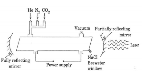
Figure 9: Co2 laser
- It consists of a quartz tube which measures 5 m long and 2.5 cm in the diameter. This discharge tube is filled with gaseous mixture of CO2(active medium), helium and nitrogen with suitable partial pressures.
- The terminals of the discharge tubes are connected to a D.C power supply. The ends of the discharge tube are fitted with NaCl Brewster windows so that the laser light generated will be polarized.
- It consists of two concave mirrors one fully reflecting and the other partially form an optical resonator.
Working:
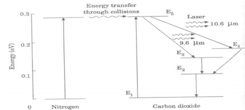
The energy levels of nitrogen and carbon dioxide molecules are as shown in figure.
|
Figure 10. Energy levels of Nitrogen and Carbon Dioxide
When electric discharge occurs in gas, the electrons collide with nitrogen molecules and raised to excited states. This process is represented by
N2 + e* = N2* + e
N2 = Nitrogen molecule in ground state e* = electron with kinetic energy
N2* = nitrogen molecule in excited state e= same electron with lesser energy
Now N2 molecules in the excited state collide with CO2 atoms in ground state and excite to higher electronic, vibrational and rotational levels.
This process is represented by the equation N2* + CO2 = CO2* + N2
N2* = Nitrogen molecule in excited state. CO2 = Carbon dioxide atoms in ground state CO2* = Carbon dioxide atoms in excited state N2 = Nitrogen molecule in ground state.
Since the excited level of nitrogen is very close to the E5 level of CO2 atom, population in E5 level increases.
As soon as population inversion is reached, any one of the spontaneously emitted photon will trigger laser action in the tube.
There are two types of laser transition possible.
Transition E5 to E4 :
This will produce a laser beam of wavelength 10.6μm
Transition E5 to E3
This transition will produce a laser beam of wavelength 9.6μm. Normally 10.6μm transition is more intense than 9.6μm transition. The power output from this laser is 10kW.
Characteristics:
- Type: It is a molecular gas laser.
- Active medium: A mixture of CO2 , N2 and helium or water vapour is used as active medium
- Pumping method: Electrical discharge method is used for Pumping action
- Optical resonator: Two concave mirrors form a resonant cavity
- Power output: The power output from this laser is about 10kW.
- Nature of output: The nature of output may be continuous wave or pulsed wave.
- Wavelength of output: The wavelength of output is 0.6μm and 10.6μm.
ADVANTAGES:
- The construction of CO2 laser is simple
- The output of this laser is continuous.
- It has high efficiency
- It has very high output power.
- The output power can be increased by extending the length of the gas tube.
DISADVANTAGES:
- The contamination of oxygen by carbon monoxide will have some effect on laser action
- The operating temperature plays an important role in determining the output power of laser.
- The corrosion may occur at the reflecting plates.
- Accidental exposure may damage our eyes, since it is invisible (infra red region) to our eyes.
2.3 APPLICATION OF LASER
Holography:
The hologram actually records the difference between two beams of coherent light.
Light is composed of waves that are of same length and travel in all directions.
The coherent light is in phase that is the waves are vibrating and travelling together in same direction.
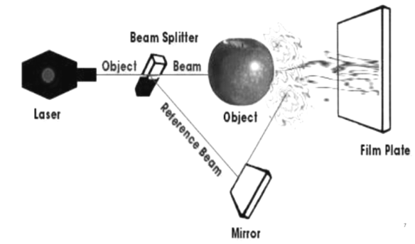
The laser beam is split into two:
- One beam stays undistributed
- Reference beam strikes photographic plate.
The second beam is called the object beam which strikes the subject and then bounces onto the plate.
The subjects interfering with second beam causes the two beams to become out of phase.
The difference is called phase interference which is recorded on the photographic plate.
|
Fig 11. Components of Hologram.
Industrial:
- Laser ablation
- Laser chemical vapor deposition
- Laser physical vapor deposition
- Non-contact bending
- Magnetic domain control
- Laser cleaning and paint stripping
- Surface roughening
- Micro-machining
- Laser marking
- Shock hardening
Medical:
Lasers are often used to:
- Treat varicose veins.
- Improve vision during eye surgery on the cornea.
- Repair a detached retina of the eye.
- Remove the prostate.
- Remove kidney stones.
- Remove tumours.
2.4 Optical Fibre
- Introduction
Acceptance angle (θ):
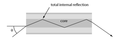
It is the maximum angle made by the light ray with the fiber axis, so that light can propagate through the fiber after total internal reflection.
|
Figure: 12. An incident light ray is first refracted and then undergoes total internal reflection at the core–cladding interface.
Acceptance Cone:
|
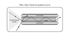
Figure 13. Acceptance cone.
- The acceptance cone is derived by rotating the acceptance angle about the fiber axis
- The maximum angle, represented in three-dimensional view as a cone, at which an optical fiber will accept incident light.
- Within that cone, as defined by those angles, a light source can inject an optical signal into the fiber core and the signal will remain in the core, reflecting off of the interface between the core and cladding, as illustrated in Figure.
- The angle of acceptance and, therefore, the cone of acceptance are determined by the difference in index of refraction (IOR) between the core and cladding.
|
Here, ncore and ncladding are the refractive indices of core and cladding, respectively, and n0 is the refractive index of the medium around the fiber, which is close to 1 in case of air.
Numerical Aperture:
Numerical Aperture (NA):It is the light gathering ability or capacity of an optical fiber.NA is related to refractive index of core (n1), cladding (n2) and outside medium (n0) as
|
Where, n(core) is core refractive index and n(cladding) is cladding refractive index.
Step index:
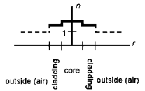
They have uniform core with one index of refraction and a uniform cladding with smaller index of refraction. When plotted on the graph as a function of distance from the center of the fiber the index of refraction resembles step-function.
|
Figure 14. Step index fiber
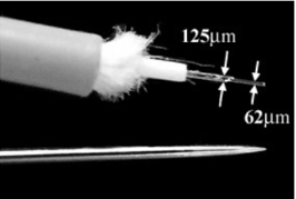
- The core of the fiber is the 62 μm-thick clear layer exposed at the right end of the fiber.
- The 125 μm-thick clear layer that comes next is cladding. The next layer is a white protective coating.
- The hair-like insulator allows the fiber to move along its axis, preventing breakage as the fiber is bent and coiled.
- The outer orange coating protects the fiber from environmental effects like moisture.
|
Fig 15. Construction
Graded index:
Definition:
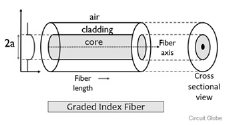
Graded Index fibre is another type of optical fibre in which the refractive index of the core is non-uniform.
This non-uniformity is present because the refractive index is higher at the axis of the core and continuously reduces with radial movement away from the axis.
However, the refractive index of the cladding is constant in case of graded index fibre. Hence the nature of the refractive index of the core is somewhat parabolic.
|
Figure 16. Graded index
In this type of fibre, the light ray experiences refraction thus gets bent towards the core. Thereby allowing propagation of ray in a curved path.
The refractive index of graded index fibre in the mathematical term is expressed as:
a is the radius of the core
r is the radial distance from the core axis
Attenuation is the reduction of signal strength and it can occur in any kind of signal like analog otherwise digital.
It is also called as attenuation lossbecause this is a normal effect of a signal while transmitting over long distances.
In some cables like conventional or FOCs (fiber optic cables), this can be identified in terms DBs (decibels) for each foot, kilometer, or thousand foot, etc.
The cable efficiency is high when the attenuation for each unit distance is less.
|
Attenuation-in signals
When it is required to send out signals over long distances through any cable, then one (or) more repeaters must be included with the length of the cable. Because repeaters play a key role in enhancing the strength of the signal to conquer this. So, this enhances the highest range of achievable communication.
Causes of Attenuation
This can be occurred in wired as well as wireless transmissions due to signaling issues. This can be occurred due to the following reasons.
- Transmission Medium
An electromagnetic field can occur around the transmission once all the signals broadcasted down, then energy losses will occur in the downside of the cable based on the length & frequency of the cable.
- Crosstalk
Crosstalk from nearby cable can cause this within cables like conductive metal or copper.
- Connectors & Conductors
- Attenuation can take place when a signal flows across dissimilar conductive standards & connector surfaces.
- The circuits can be attenuated by using repeaters for signal boosting via amplification. When copper conductors are used, then the high-frequency signal and additional attenuation can occur with a length of cable.
- Present communications use HFs (high-frequencies), thus the mediums which have a smooth-attenuation in all frequencies like fiber optics are employed instead of normal copper circuits.
- Noise
Additional noise on N/Ws (networks) such as RFs (radio frequencies), leakage in wires, electrical currents can interfere by the signal to cause this. If the noise is more, then this will be more.
- Physical Environs
Physical environs which include installation of improper wiring, wall barriers, the temperature can alter the transmission, then attenuation can be caused.
- Travel Distance
When the transmission in a cable travels for long distances like from source (current place) to destination (connection supplier), then it experiences more noise while traveling.
Basic building blocks of communication
|
The block diagram of a communication system will have five blocks, including the information source, transmitter, channel, receiver and destination blocks.
1.Information source :-
- The objective of any communication system is to convey information from one point to the other. The information comes from the information source, which originates it
- The physical manifestation of the information is termed as message signal
2.Transmitter:-
- The objective of the transmitter block is to collect the incoming message signal and modify it in a suitable fashion such that it can be transmitted via the chosen channel to the receiving point.
- Channel is a physical medium which connects the transmitter block with the receiver block.
- The functionality of the transmitter block is mainly decided by the type or nature of the channel chosen for communication.
3.Channel: -
- Channel is the physical medium which connects the transmitter with that of the receiver.
- The physical medium includes copper wire, coaxial cable, fibre optic cable, wave guide and free space or atmosphere.
- The choice of a particular channel depends on the feasibility and also the purpose of the communication system.
4.Receiver: -
- The receiver block receives the incoming modified version of the message signal from the channel and processes it to recreate the original (non-electrical) form of the message signal.
- There are a great variety of receivers in communication systems, depending on the processing required to recreate the original message signal and also final presentation of the message to the destination.
5.Destination: -
- The destination is the final block in the communication system which receives the message signal and processes it to comprehend the information present in it.
- Usually, humans will be the destination block.
Advantages of optical fibre communication:
Enormous Bandwidths
The information carrying capacity of a transmission system is directly proportional to the carrier frequency of the transmitted signals. The optical carrier frequency is in the range of 10 to 14Hz while the radio frequency is about 106Hz. Thus, the optical fibres have enormous transmission bandwidths and high data rate.
Low transmission loss
Due to the usage of ultra low loss fibres and the erbium doped silica fibres asoptical amplifiers, one can achieve almost loss less transmission. Hence for long distance communication fibres of 0.002 dB/km are used. Thus the repeater spacing is more than 100 km.
Immunity to cross talk
Since optical fibres are dielectric wave guides, they are free from any electromagnetic interference (EMI) and radio frequency interference (RFI). Since optical interference among different fibres is not possible, cross talk is negligible even many fibres are cabled together.
Electrical Isolation
Optical fibres are made from silica which is an electrical insulator. Therefore, they do not pick up any electromagnetic wave or any high current lightening. It is also suitable in explosive environment.
Small size and weight
The size of the fibre ranges from 10 micrometres to 50 micrometres which isvery small. The space occupied by the fibre cable is negligibly small compared toconventional electrical cables. Optical fibres are light in weight. These advantages make them touse in aircrafts and satellites more effectively.
Signal security
The transmitted signal through the fibre does not radiate. Unlike in copper cables, a transmitted signal cannot be drawn from a fibre without tampering it. Thus, the opticalfibre communication provides 100% signal security
Reference:
1. Engineering Physics-Avadhanulu, Kshirsagar, S. Chand Publications
2. A textbook of optics- N Subrahmanyam and BriLal , S. Chand Publications
3. Engineering Physics- Gaur, Gupta, Dhanpat Rai and Sons Publications

