Unit - 7
Vector Mechanics of Particles
Assume a rectangular Cartesian coordinate system.
Let  and
and  be orthogonal unit vectors of that system:
 ,(1)
,(1)
Where  is the Kronecker delta symbol.
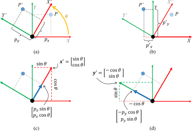
By rotation of the coordinate system, we achieve a new rectangular coordinate system.
Let  and
and be orthogonal unit vectors of the new coordinate system
  , that is,
 ,(2)
,(2)
By the theorem of directional cosines, the coordinates of the vectors  in the source of vectors
  are the directional cosines. If we signify the directional cosines of the vector
  (with n = 1, 2, 3) through
  , respectively, then


Which can be written in a short form as
 (n = 1, 2, 3).(3)
Equalities (1) and (2) imply
 (i, j =1, 2, 3).(4)
Rewrite equivalences (3) and (4) in the matrix form.
Let  be the matrix of the directional cosines. Introduce also the column matrices
  and
and  . Then
 ,
,
 ,
,
Where  is the transfer of matrix U, and I is the identity matrix.
Note that the transfer of U is also the inverse of U. Then, we can easily find the formula of the inverse conversion (from the old basis to the new one):


That is,
 (n = 1, 2, 3).
Now learning the transformation of the coordinates of an arbitrary vector a.
Some vector a can be stated as the linear grouping of basis vectors. If a1, a2 and a3 are the coordinates of a in the basis, and a'1, a'2 and a'3 are the coordinates of a in the new source then
 (5)
(5)
 .(6)
.(6)
Thus,
 .
.
In view of equality (3) we obtain


That yields the methods of transformation of the coordinates:
 .(7)
.(7)
Similarly,
 .
.
Till now we have interpreted the scalar product of vectors as a scalar quantity without a formal proof, seeing this proposition as the self-evident truth. A difficult explanation follows from the below theorem.
Theorem
The scalar product is invariant under rotation of the coordinate system.
Proof: Actually, using formulas (7) we get

Therefore, the theorem.
Fundamental force also known as fundamental interface within physics some of the four essential forces are gravitational force, electromagnetic force, strong force and weak force that rule how substance or particles interconnect and how definite particles decay. All the identified forces of nature be able to be traced to these fundamental forces.
Now to prove that Newton' law invariant we need to find  and
and
 and plug them back into Newton's second law,


Now plugging these into Newton's equation we get,

Therefore the form of Newton's law doesn't change under Galilean transformation.
RESULT
Plugging Galilean transformation into Newton's law we get that it is invariant under the Galilean transformation.
Invariance of Newton's second law
In frame S

We can see that the direction of acceleration is the same as the force and that

Is the inertial mass, i.e. the resistance of a body to it being accelerated.
Note that only external forces can chane the state of motion (I cannot lift myself, for example).
To finish our conversation of the equations of motion in two dimensions, we will observe Newton's Second law as it is useful to the polar coordinate system.
In its simple form, Newton's Second Law states that the addition of the forces on a body will be equivalent to mass of that body times the rate of acceleration. For bodies in motion, we can write this connection out as the calculation of motion.
∑→F=m∗→a∑F→=m∗a→
Just as we did with rectangular and normal-tangential coordinates, we will break this single vector calculation into two distinct scalar calculations. This includes recognizing the r and theta directions and then using sines and cosines to break the given forces and accelerations down into components in those directions.
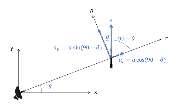
When functioning in the polar coordinate system, any given forces or accelerations can be broken down by means of sines and cosines assuming the angle of the force or acceleration is known comparative to the r and theta directions.
∑Fn=m∗ar∑Fn=m∗ar
∑Ft=m∗aθ∑Ft=m∗aθ
In specific, we will often additional the known values below for the r and theta components for acceleration.
Ar=¨r−r˙Θ2ar=r¨−rΘ˙2
aθ=2˙r˙Θ+r¨Θaθ=2r˙Θ˙+rΘ¨
Polar coordinates can be used in any kinetics problem, though they work best with problems where there is a stationary body following some moving body (such as a radar dish) or there is a particle revolving around some fixed point. These calculations will also come back into play when we start examining rigid body kinematics.
Friction acting at one fixed horizontal surface – Example

The maximum value of the force F such that the block shown in the arrangement, does not move is given by:
Block does not move till the horizontal force on it becomes more than the maximum static frictional force.


7.7.1 Cylindrical Coordinates
Cylindrical coordinates are a simple allowance of the two-dimensional polar coordinates to three dimensions. Recall that the position of a point in the plane can be described using polar coordinates (r,θ)(r,θ). The polar coordinate rr is the distance of the point from the origin. The polar coordinate θ is the angle between the xx-axis and the line segment from the origin to the point. Polar coordinates are showed in the below figure

The cylindrical coordinates simply combine the polar coordinates in the xxy plane with the usual zz coordinates of the Cartesian coordinates. To form the cylindrical coordinates of a point PP, it is sufficient to project it to a point QQ in the xxy plane (see the following figure). So, take the polar coordinates (r, θ) (r, θ) of the point QQ, that is, rr is the distance from the origin to QQ and θθ is the angle between the positive xx axis and the line segment from the origin to QQ. The third cylindrical coordinate is equal to the usual zz coordinate. It is the distance of the signed point PP with respect to the xxy plane (being negative, it is PP is below the xxy plane). The following figure shows the cylindrical coordinates (r, θ, z) (r, θ, z) of the point PP.
You can further explore the properties of cylinder coordinates with the following applet. You can see how changing the coordinates (r, θ, z) (r, θ, z) changes the position of the PP point. As with the polar coordinates, we generally limit 0≤θ<2π0≤θ<2π and r≥0r≥0 to reduce the non-uniqueness of the cylinder coordinates. However, when r = 0r = 0, there is a non-uniqueness since the point PP is on the zz axis when r = 0r = 0, regardless of the value of θθ.
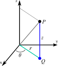
Cylindrical coordinates. Given the values for the cylindrical coordinates rr, θθ, and zz, the large blue dot shows the corresponding position in the Cartesian coordinates. You can edit rr, θθ and zz using the cursors or dragging the other displayed dots. The red dot is the projection of the large blue dot on the xxy plane. This projection offers perspective and helps visualize θθ and rr. The rr coordinate is the length of the red line segment from the origin to the red point. The coordinate is the angle formed by the red line segment with the positive xx axis; is the angle of the green portion of the disk portion in the xxy plane. The zz coordinate is equal to the zz coordinate of the Cartesian coordinates; is the height of the purple point on the zz axis.
7.7.2 Spherical Coordinates
The distance from the origin to a point in space is denoted by ρ (the Greek letter rho). The points at a constant distance ρ * t from the origin form a sphere of radius r. A point in space is located by
1. Its distance ρ from the origin
2. the angle φ (the Greek letter phi) a line from the origin to the point makes with the positive z-axis and
3. The angle θ(the Greek letter theta) that the projection of this line into the xy-plane makes with the positive x-axis
These spherical coordinates are written P = (p, θ, φ)

If a force acting on an object is only a function of position, it is said to be a conservative force and can be represented by a potential energy function that satisfies the derived condition for a one-dimensional case
 conceptual comment Example
The integral form of this relationship is
 Example
Which can be taken as a definition of potential energy. Note that there is an arbitrary integration constant in that definition, demonstrating that any constant can be added to potential energy. In practice, this means that zero potential energy can be set at any convenient point.
Equipotential surfaces
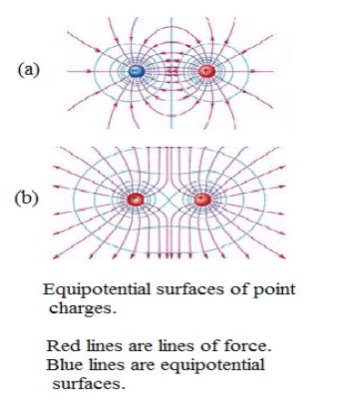
An equipotential surface is a surface at all points where the potential has the same value. Figure 3 shows sections of the equipotential surfaces associated with two different charges and two similar charges.
Since the potential energy of a charged body is the same at all points on a particular equipotential surface, it follows that no work is done to move a charged body on such a surface. Consequently, the equipotential surface passing through any point must be at right angles to the direction of the electric field at that point. Otherwise, the field would have a component on the surface and you would have to work against the field to move a charge in the direction of this component. Therefore, the lines of force and the equipotential surfaces form a mutually perpendicular network.In a charged conductor in which the charges are at rest (electrostatic situation), the lines of force on the surface are perpendicular to the surface. Then, the surface of said conductor is an equipotential surface. Furthermore, since the field inside a charged conductor iszero, the entire interior of the conductor is an equipotential volume, with the same potential as the surface.


7.9.1 F = - Grad V


7.9.2 Equipotential Surfaces
Equipotential surfaces
An equipotential surface is a surface at all points where the potential has the same value. Figure 3 shows sections of the equipotential surfaces associated with two different charges and two similar charges.
7.9.3 Meaning of Gradient
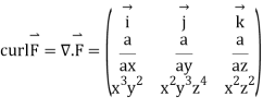
The gradient is a vector process which operates on a scalar function to make a vector whose magnitude is the utmost rate of change of the function at the point of the gradient and which is sharp in the direction of that utmost rate of change. ... The divergence of the gradient is known as the LaPlacian.
Conservative forces:
Conservative forces are those for whom the work done depends only on the start and end points.
For example, gravitational force, electrostatic force
Non-conservative forces:
Nonconservative forces are those in which the work done or the kinetic energy depended on other factors, such as speed or the particular path taken by the object.
For example, friction force
S.no. | Conservation forces | Non- conservative forces |
1 | Work done does not depend upon path. | Work done depends on path. |
2 | Work done in a round trip is zero. | Work done in a round trip is not zero. |
3 | Central insecure. | Forces are velocity dependent and retarding in nature. |
4 | When only a conservative force acts within a system, the kinetic energy and potential energy can change however their sum, the mechanical energy of the system, does not change. | Work done against a non- conservative force may be dissipated as heat energy. |
5 | Work done is completely recoverable. | Work don is not completely recoverable |
In classical mechanics, a central force on an object is a force that is focused alongside the line linking the object and the origin: where is the force, F is a vector valued force function, F is a scalar valued force function, r is the position vector, ||r|| is its length, and = r/||r|| is the equivalent unit vector
Central forces act either towards or away from the origin (depending on their sign) with a magnitude dependent only on the distance the object is away from the origin .
Note:- 


A central force is a force (probably negative) to points from the particle straightforwardly towards an unchanging point in space, the center, and whose magnitude only depends on the distance of the object to the center.
In the absence of an external torque, angular momentum is conserved:

This is the law of conservation of angular momentum,
The total angular momentum of a rotating object remains constant if the net external torque acting on it is zero.
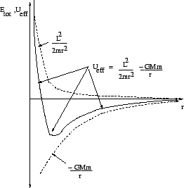
Let's write the total energy of a particle touching in a gravitational field in a clever way:


Where

Is the (radial) potential energy plus the transverse kinetic energy (connected to the constant angular momentum of the particle). If we plot the actual potential (and its pieces) we acquire a one-dimensional radial energy plot.
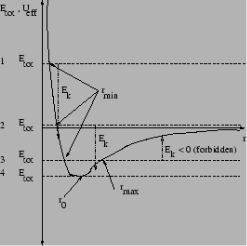
By representation a constant total energy on this plot, the modification between  is the radial kinetic energy, which must be positive. We can regulate lots of exciting things from this diagram.
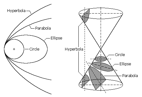
In this figure, we show orbits with a given angular momentum  and four general total energies
  .
.
These orbits have the succeeding features and names:
 This is a hyperbolic orbit.
 This is a parabolic orbit. This orbit describes escape velocity as we shall see later.
 This is usually an elliptical orbit (consistent with Kepler's First Law).
 . This is a circular orbit. This is a special case of an elliptical orbit, but merits special mention.
Note well that entirely of the orbits are conic units. This exciting geometric joining between  forces and conic orbits was a wonderful motivation for important mathematical work two or three hundred years ago.

A conical, or simply conical, section is a curve formed by passing a plane through a right circular cone. As shown in Figure the angular orientation of the plane with respect to the cone determines whether the conic section is a circle, an ellipse, a parabola, or a hyperbola. The circle and ellipse rise when the connection of the cone and the plane is a limited curve. The circle is a special case of the ellipse in which the plane is perpendicular to the axis of the cone. If the plane is parallel to a cone generating line, the conic is called a parabola. Finally, if the intersection is an unlimited curve and the plane is not parallel to a cone generating line, the figure is a hyperbola. In the latter case, the plane will intersect together halves of the cone, making two separate curves.
We can define all the conic sections in terms of eccentricity. The type of conical section is also related to the semi-major axis and energy. The following table shows the relationships between eccentricity, semi-major axis and energy and the type of conic section.
Conic Section | Eccentricity, e | Semi-major axis | Energy |
Circle | 0 | = radius | < 0 |
Ellipse | 0 < e < 1 | > 0 | < 0 |
Parabola | 1 | Infinity | 0 |
Hyperbola | > 1 | < 0 | > 0 |
Concentric section eccentricity, and semi-major energy axis.
Circle 0 = radius <0
Ellipse 0 <and <1> 0 <0
Parabola 1 overflow 0
Hyperbola> 1 <0> 0
Satellite orbits can be one of the four conical sections. This page is primarily about elliptical orbits, although we conclude with an examination of the hyperbolic orbit.
The movement of the sun and the earth is an example of a two-body problem ''. This is a relatively simple problem that can be solved analytically (it is interesting to note here, however, that adding a new object to the problem, for example the moon, makes it completely intractable. This is the famous three-body problem. ''). We can assume that, with a good approximation, the sun is stationary and is a convenient origin of our coordinate system. This is equivalent to moving to a center of mass '' coordinate system, where most of the mass is concentrated in the sun. The problem can be reduced to an equivalent body problem involving a reduced object mass given by

Meanwhile the mass of the earth is 
Kg and the mass of the sun is  kg we find that for most practical purposes, the compact mass of the earth-sun system is that of the earth.
Henceforth, in the succeeding we are successful to consider the problem of a single particle of mass m moving about an immovable center of force, which we take as the origin of the coordinate coordination. The gravitational force on the particle m is given by

Where the vector r is directed from M to m, and G is the gravitation constant
The negative sign suggests that the gravitational force is attractive and decreases with the separation r. The gravitational force is a central force'': its magnitude depends on the separation between the particles and its way is along the line that joins them. The statement is that the motion is confined to the xy plane. The angular momentum L lies on the third direction z and is a constant of motion, i.e. it is conserved:
An added constant of motion in the total energy E given by

If we answer the coordinate system in the sum, the equation of motion is

For computational purposes it is suitable to write it down in cartesian components:


Hence, the calculations of motions in cartesian coordinates are:


Where  . These are coupled differential equations, meanwhile each differential equation comprises both x and y.
A manoeuvre is achieved using the satellite's momentum subsystem to fire thrusters and take about a change in the orbital elements. A manoeuvre may include one or more burns. There are three common types of manoeuvres:

1. Orbit elevation manoeuvre:
Increases the semi-major axis. Cases include drag manoeuvres (DMUs), which counteract the belongings of atmospheric resistance and reinitialize the circulation orbit of a satellite; some types of risk mitigation (RMM) manoeuvres are achieved to avoid orbital debris; and escalate manoeuvres to place new satellites in the mission's orbital position.
2. Orbit descent manoeuvre:
The semi-major axis decreases. Cases include the braking manoeuvres used to avoid exit the collection control panel; some types of risk mitigation (RMM) manoeuvres are done to avoid orbital debris; and exit manoeuvres for satellites leaving their nominal orbital position.
3. Tilt Adjustment Manoeuvre (AMI):
Performed periodically to keep the Average Local Mission Time (MLT) within a predefined range.
A non-inertial frame of reference is a frame of reference that is accelerated from an inertial frame. An accelerometer at rest in a non-inertial frame will generally detect non-zero acceleration.

In a rotating coordinate system, a free particle transfers in a way that seems to be affected by three forces: the centrifugal force, the Coriolis force and the Euler force. These forces rise only from the rotation of the coordinate system. A free particle measured from a fixed, and a rotating set of co-ordinate axes.
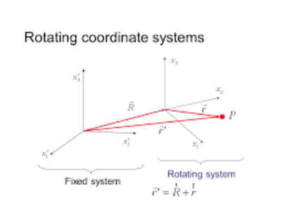
Rotary coordinate system
The arithmetic for rotary coordinate systems can be quite complicated, however most physics can be understood in a relatively simple case. First, we will study the simple case, then we will expand the equations a little to include the general case.
Meanwhile any rotation is just a rotation in a plane, the simple case comprises the most overall rotation. Our simplification is that we will insert two coordinate axes in the plane of rotation. Since we have the choice of coordinate systems to solve our physics problems, this covers many cases. But sometimes, like motion on the earth's surface, we want to define our coordinates differently, and we'll cover that in the next section. In all cases, we will set our coordinates to match the origin of the inertial coordinate system and the rotary coordinate system.
Imagine investigating on a rotary table (rotation in the plane of the table). It is rotating around a definite point and we will call the point the origin of our coordinate systems.We know about the effective'' centrifugal force  from Freshman Physics. If the table is revolving with constant angular frequency , we require
  .
.

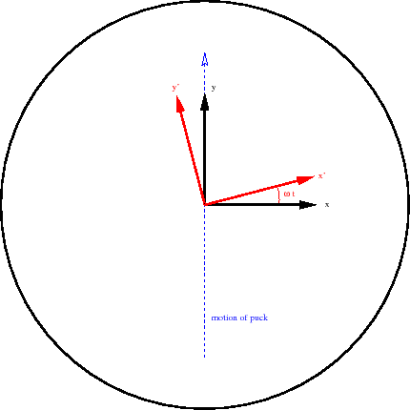
There is extra effective force that be determined by on velocity called the Coriolis Force. Let’s recognize this just by supposing our rotating table is a frictionless air table. For our first experiment we will send a puck straight across the table through the origin. The puck energies from radius  to radius r=0 and back to radius r1 in our experiment and we give the puck precisely the right velocity so that it marks this trip while the table experiences precisely one-half turn.

So far, we are talking about the motion detected from a non-rotating frame with the same origin.
The puck transfers in a straight line at constant velocity from one side of the table to the new as shown in the figure below.
Now let’s see what occurs using the rotating coordinate system. The figure below gives a rough picture of the puck's path in the rotating coordinate system. It does not move in a straight line.
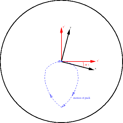
The disc appears with an internal radial velocity as before but also has a huge tangential component. The tangential component decreases as the disk approaches the origin. Cross the origin, then return to radius r1 on a path symmetrical with that of the origin. (Return to the same point due to the speed we chose for this experiment.)
In the rotating frame, there was clearly an effective force that was not radially outward. That was the Coriolis force.
Acceleration of a particle in a mobile frame of reference
The XYZ system shown in Figure 1 is an inertial frame of reference, while the X'Y'Z 'frame is a mobile (translation + rotation) frame of reference. The position of point P in the figure can be stated in terms of these two frames of reference:
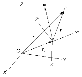

Where ro = the position of the origin of the revolving frame, and r' = the position of P comparative to the origin of the moving frame.
From above equation of Rotating Reference Frame, the displacement of point P can then be expressed as


Where dro = the displacement due to conversion of the origin of the rotating frame, dr' = the displacement of point P relation to the origin of the rotating frame, d x r' = the displacement due to rotation of the moving frame, and (dr')rot, the displacement of point P detected in the rotating frame (or the displacement of P relative to the moving frame).
From above equation the velocity of point P can be expressed as


Where, v'r = the velocity of point P comparative to the moving reference frame.
Therefore, the velocity of point P comparative to the origin of the moving reference frame can be divided into the velocity due to rotation of the frame and the velocity detected in the rotating frame.
Acceleration of point P can then be found likewise:


Where, a is the acceleration of point P, ao is the acceleration of the origin of the moving frame, and a'r is the acceleration of point P relative to the moving frame.
Centripetal Acceleration
Above term are the results of the translational and rotational acceleration of the moving reference frame, respectively. The 3rd term, x (x r'), is due to the rotation of the moving frame and, as shown in Figure 2, this vector heads toward the center of rotation (point C). This acceleration is named the centripetal acceleration. The above term is due to the motion of the point within the moving frame and is called the Coriolis acceleration. The previous term is due to the acceleration of the point inside the moving reference frame.
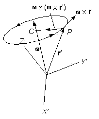
Figure
If the moving frame does not interpret but rotates with a constant angular velocity and point P does not move inside the moving frame, [4] can be basic to
 [5]
[5]
Meanwhile
 [6]
[6]
In order words, the centripetal acceleration is the basic must for a constant circular motion of a body around an axis of rotation. According to Newton's 2nd Law of Motion the force acting on a particle is equivalent to the its mass times acceleration. Therefore, from [6]:
 [7]
[7]
This force is the centripetal force which causes a constant circular motion of a body. Note that this force acts in the direction of the centre of rotation, point C shown in Figure 2.
If the angular velocity of the rotating position frame is not constant, [4] decreases to
 [8]
[8]
Meanwhile
 [9]
[9]
In the case of planar rotation where the direction of the angular velocity does not change, the 1st term of [8] can be labelled as the tangential acceleration since it is in the direction of x r' shown in Figure 2. (The angular velocity vector and the angular acceleration vector show the same direction in this case.) The 2nd term then converts the radial acceleration.
EATHER ASSOCIATED WITH THE PASSAGE OF A CLASSIC DEPRESSION | |||||
| Ahead of the warm front | Passage of the warm front | Warm sector | Passage of the cold front | Cold sector |
Pressure | Starts to fall steadily | Continues to fall | Steadies | Starts to rise | Continues to rise |
Temperature | Quite cold, starts to rise | Continues to rise | Quite mild | Sudden drop | Remains cold |
Cloud cover | Cloud base drops and thickens (cirrus and altostratus) | Cloud base is low and thick (nimbostratus) | Cloud may thin and break | Clouds thicken (sometimes with large cumulonimbus) | Clouds thin with some cumulus |
Wind speed and direction | Speeds increase and direction backs | Veers and becomes blustery with strong gusts | Remain steady, backs slightly | Speeds increase, sometimes to gale force, sharp veer | Winds are squally |
Precipitation | None at first, rain closer to front, sometimes snow on leading edge | Continues, and sometimes heavy rainfall | Rain turns to drizzle or stops | Heavy rain, sometimes with hail, thunder or sleet | Showers |
Foucault's pendulum or Foucault's pendulum is a simple device named after the French physicist Léon Foucault and conceived as an experiment to demonstrate the rotation of the Earth. The pendulum was introduced in 1851 and was the first experiment to provide simple and direct evidence of Earth's rotation.
Foucault's pendulum is a simple experiment that demonstrates the rotation of the Earth. When Léon Foucault first performed the experiment in 1851, the idea of the Earth spinning was nothing new or radical; the pendulum's accomplishment was to provide evidence that required no minimal observations of stars or other objects far from Earth. Foucault's pendulum is a highly localized and easy-to-prepare experiment whose result is clear, powerful, and accessible even to non-scientists. In short, the pendulum provides everything a science teacher could ask for in a teaching experiment.
So how does it work? The elegant answer is that the pendulum swings in a fixed plane and the Earth rotates below it, but this explanation is misleading. At the north or south pole, the pendulum moves in a fixed plane (if we neglect the fact that the Earth also rotates through space), then the pendulum plane appears to rotate 360 ° while the Earth makes a complete rotation. However, at any other point on Earth, the point where the pendulum is connected cannot be considered a "fixed point", since that point also moves as the Earth rotates. The plane in which the pendulum swings is also in motion. For this reason, the time it takes for the pendulum to complete one rotation (with respect to the surrounding environment) is equal to one sidereal day (23.93 hours) divided by the sine of the latitude of its position. Since sin (0) = 0, the plane of a pendulum located at the equator will not appear to move at all.
For a pendulum experiment to be accurate, precautions must be taken to ensure that the pendulum is not attacked by external forces other than gravity. For example, to make the pendulum move, it is usually held at an angle with a rope, which the experimenter burns to free the pendulum. Letting the pendulum slip away from your hands or even cut the string could give the pendulum an unwanted momentum in a particular direction. A heavy pendulum on a long, stiff cable can continue to swing for long periods of time, but eventually air resistance will decrease and stop movement. Museums often use an electromagnetic pulse to keep their pendulum moving, as this installation provides additional energy to the pendulum without affecting its direction of movement.
On Earth, we call the apparent force due to Earth's rotation the Coriolis force, a force that is primarily responsible for weather patterns and ocean currents. Contrary to popular belief, the Coriolis force does not drain toilets in opposite directions in the northern and southern hemispheres; In fact, this phenomenon is not even real. The direction in which a sink or toilet is drained depends on many factors, including any pre-existing rotational motion in the water, as well as the forces applied at the start of the drain. In experiments where drainage is done very carefully, and usually weeks after the initial pour of water, the direction of drainage will correspond to the Coriolis force, but these conditions are certainly not present in everyday situations.
In classical mechanics, a harmonic oscillator is a arrangement that, when moved from its balance position, involvements a restoring force F relative to the displacement x: where k is a positive constant.
A diatomic molecule vibrates somewhat like two masses on a spring with a potential energy that depends upon the square of the displacement from equilibrium. But the energy levels are quantized at equally spaced values.
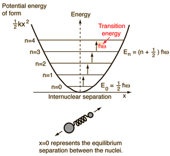
The energy levels of the quantum harmonic oscillator are


h=plank’s constant/2
And for a diatomic molecule the natural frequency is of the form
 k=bond force constant
 reduced mass
Where the reduced mass is given by

This frequency shape is the same as the classical simple harmonic oscillator. The most notable difference for the quantum case is the so-called "zero-point vibration" of the ground state n = 0. This implies that the molecules are not completely at rest, even at absolute zero temperature.
The quantum harmonic oscillator has suggestions distant outside the simple diatomic molecule. It is the basis for understanding complex modes of vibration in larger molecules, the motion of atoms in a solid network, the theory of heat capacity, etc. In real systems, the energy distances are the same only for the lower levels where the potential is a good approximation of the harmonic "mass in a spring" potential. The anharmonic terms that appear in the potential of a diatomic molecule are useful for mapping the detailed potential of such systems.
A large system moves slowly toward equilibrium. An undersized system moves rapidly toward equilibrium, but will oscillate around the equilibrium point when it does. A critically damped system moves as fast as possible towards equilibrium without oscillating around equilibrium.
DAMPED OSCILLATIONS
- To date our conversation of SHM has expected that the motion is frictionless, the total energy (kinetic plus potential) remains constant and the motion will continue endlessly.
- Of development in real world situations this is not the case, frictional forces are always present such that, without external involvement, oscillating systems will always come to rest. The frictional (damping) force is often proportional (but opposite in direction) to the velocity of the oscillating body such that


Where b is the damping constant.
- This differential equation has solutions

Where  when the damping is small (small b).
Announcement that this solution signifies oscillatory motion with exponentially reducing amplitude
7.21.1 Overdamped simple harmonic motion
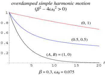
Overdamped simple harmonic motion is a special case of damped simple harmonic motion
 (1)
(1)
In which
 (2)
(2)
Therefore
 (3)
(3)
 (4)
(4)
 (5)
(5)
Where
 (6)
(6)
The general solution is therefore
 (7)
(7)
Where A and B are constants. The initial values are
 (8)
(8)
 (9)
(9)
So
 (10)
(10)
 (11)
(11)
The above plot shows an over damped simple harmonic oscillator with  and three different initial conditions (A,B)
For a cosinusoidally forced over damped oscillator with forcing function  , i.e.,
 (12)
(12)
The general solutions are
 (13)
(13)
 (14)
(14)
Where
 (15)
(15)
 (16)
(16)
These give the identities
 (17)
(17)
 (18)
(18)
And
 (19)
(19)
 (20)
(20)
We can now use variation of parameters to obtain the particular solution as
 (21)
(21)
Where
 (22)
(22)
 (23)
(23)
And the Wronskian is
 (24)
(24)
 (25)
(25)
These can be integrated directly to give
 (26)
(26)
 (27)
(27)
Integrating, plugging in, and simplifying then gives
 (28)
(28)
 (29)
(29)
Where use has been made of the harmonic addition theorem and

7.21.2 Critically Damped Simple Harmonic Motion
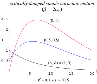
Critical damping is a special case of damped simple harmonic motion
 (1)
(1)
In which
 (2)
(2)
Where β is the damping constant. Therefore
 (3)
(3)
In this case, D=0 so the solutions of the form satisfy
 (4)
(4)
One of the solutions is therefore
 (5)
(5)
In order to find the other linearly independent solution, we can make use of the identity
 (6)
(6)
Since we have  simplifies to
 . Equation (6) therefore becomes
 (7)
(7)
The general solution is therefore
 (8)
(8)
In terms of the constants A and B, the initial values are
 (9)
(9)
 (10)
(10)
So
 (11)
(11)
 (12)
(12)
The above plot shows a critically damped simple harmonic oscillator with,  ,
, for a variety of initial conditions (A,B)
For sinusoidally forced simple harmonic motion with critical damping, the equation of motion is
 (13)
(13)
And the Wronskian is
 (14)
(14)
 (15)
(15)
Plugging this into the equation for the particular solution gives
 (16)
(16)
 (17)
(17)
Applying the harmonic addition theorem then gives
 (18)
(18)
Where
 (19)
(19)
7.21.3 Lightly damped oscillator
A lightly damped harmonic oscillator transfers with ALMOST the same frequency, but it loses amplitude and velocity and energy as times goes on. The timescale over which the amplitude decays is linked to the time constant tau.As the resistive force rises (b rises), the decay occurs more rapidly.

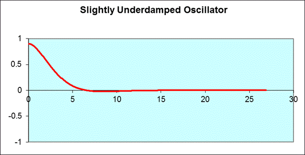
A system's natural frequency is the frequency at which the system will vacillate if not precious by driving or damping forces. A periodic force driving a harmonic oscillator at its natural frequency produces resonance.The fewer damping a system has, the higher the amplitude of the forced oscillations near resonance.
Supposing now that instead of permitting our system to vacillate in isolation we apply a "driving force". For example, in the case of the (vertical) mass on a spring the driving force might be useful by having an external force (F) move the maintenance of the spring up and down. In this case the equation of motion of the mass is given by,
 One common condition happens when the driving force itself oscillates, in which case we may write

Where  is the (angular) frequency of the driving force.
This equation has solutions of the form

Where the amplitude of these oscillations, B, depends on the parameters of the motion, 

The amplitude, B, has a determined value when  . This is called the resonance condition. Note that at resonance, B, can become very large if b is small. (In the diagram at right
  is the natural frequency of the oscillations,
  , in the above analysis). In designing physical systems, it is very important to find the system's natural frequencies of vibration and provide sufficient damping in case of resonance. This clearly did not occur in the design of the Tacoma Narrows Bridge (Tacoma Narrows Newsreel) in 1940.
There are many physical and engineering systems where resonance is very important e.g., shock absorbers, earthquakes, loudspeakers, NMR, microwave ovens etc.
References:
1. An Introduction to The Mechanics of Solids, 2nd Ed. With Si Units — Sh Crandall, Nc Dahl &Tj Lardner
2. Engineering Mechanics: Statics, 7th Ed. — JlMeriam
3. Engineering Mechanics of Solids — Ep Popov