Unit - 8
Planar Rigid Body Mechanics
A rigid body performs plane motion when entirely parts of the body move in parallel planes. It follows that all particles in a rigid body move in circular paths about the axis of rotation, and all lines in the body which are perpendicular to the axis of rotation rotate over the identical angle in the same time.
In geometry, a plane of rotation is a theoretical object used to explain or imagine rotations in space. In three dimensions it is another to the axis of rotation, but dissimilar the axis of rotation it can be used in new dimensions, such as two, four or more dimensions. Scientifically such planes can be described in a number of ways. They are able to be describing in terms of planes and angles of rotation. They able to be linked with bivectors from geometric algebra. They are associated to the Eigen values and eigenvectors of a rotation matrix. And in particular dimensions they are associated to other algebraic and geometric property, which can then be generalize to other dimensions.
Rotation and Translation
To describe the motion of an object undergoing pure rotation (rotation), we must describe the circular motion to which each point on the object is subjected. What should we do if the object rotates and translates simultaneously (moving in a plane perpendicular to the axis of rotation), like a wheel rolling on an incline?
The answer lies in the independence of these two types of movement. In the same way that we attack kinematics in two dimensions independently analysing horizontal and vertical movements, we will attack rigid body kinematics independently analysing rotational and translational movements. In summary, we will model any motion of a rigid body as an overlay of a translation of the object's center of mass (CM) (which we will analyse with particle kinematics) and a rotation about an axis that passes through the CM (which we will analyse with rotating kinematics, labelled above).
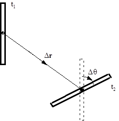
For example, examine the movement of the thin rod between t1 and t2. Although the bar may have rotated crazily in the space between these two times, we can model its movement as an overlay of a simple translation of your CM without rotation, leaving the bar in the orientation indicated by the dotted lines and a simple rotation around to an axis through its CM without translation, which leaves the bar in its correct final orientation. If we imagine that the time difference (t2 - t1) is reduced to zero, it is expected to be plausible to be able to model any movement through this method.
In summary, to describe the movement of an arbitrary rigid body, we will divide it into a pure translation of the CM and a pure rotation around the CM. We will use particle kinematics to describe the rotational portion. The velocity (or acceleration) of any point on the object is determined by the sum of the velocity (or acceleration) due to translation and the velocity (or acceleration) due to rotation.
8.4 Angular Momentum about a point of a Rigid Body in Planar Motion
The angular Momentum of a Rigid Object Rotating and Translating
Consider a rigid object of mass m that translates with a velocity vcm and rotates with an angular velocity ω about an axis that passes through its center of mass as shown below. The movement of the object is contained in the xy plane and the axis of rotation is along the z axis.
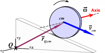
Let Q be the point near which the position of the center of mass of the body,  , is measured. Now, the angular momentum about point Q:

Where Icm is the moment of inertia of the thing about its center of mass.
Decomposing the motion in Translation and Rotation
The angular momentum is decomposed into two vector parts:
Orbital (translation of the center of mass): | Spin (rotation about the axis): |
 |  |
It signifies the angular momentum near point Q of a point particle of mass m interpreting with speed vcm. | It is the angular momentum linked to the rotational motion of the bodynearby an axis passing over its center of mass. |
Inertial frame:
The observable form of the laws of mechanics depends on the frame used to reference the motions. The reference frame is frequently the related of the event, the earth being the most common reference frame. For example, Newton’s second law is written as

When the acceleration a is calculated comparative to an inertial reference frame. The points of an inertial frame have no acceleration (only converting with constant or zero velocity, and no rotation). On the other hand, this same law will be written as

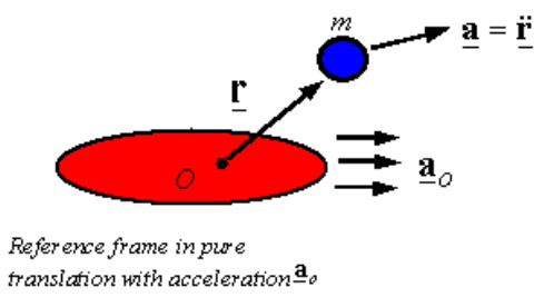
If the acceleration is considered with respect to a frame that is translated purely with an acceleration of. Therefore, it is important to carefully consider the framework before using any particular form of a particular law. Most of the time, the laws of motion are written in relation to an inertial structure, so the form of the law related to other structures can be derived in this way.
Euler's Laws:
The laws of motion for a rigid body are well-known as Euler's laws. Euler presented two laws for the motion of a rigid body. The two written laws related to an inertial frame of reference are


Where O is a fixed point in the inertial frame of reference. The first of Euler's two laws describes how forces control the "translational" motion of the rigid body (that is, the change in the speed of the center of mass). The second of Euler's two laws describes how the change in the angular momentum of the rigid body is controlled by the moment of forces and torques applied to the body. Euler's laws are written for a body of fixed matter (that is, matter cannot be added to the body, matter cannot be subtracted from the body, and matter cannot be replaced by other matter).
An alternative form of these laws that replaces the need to have a fixed-point O in an inertial structure is obtained using the center of mass. This law is derived below and is given by


A third alternative form of Euler's laws can be derived from the second alternative form. This shape replaces the center of mass with an arbitrary point P that can move in any way (can accelerate). This form of Euler's laws is written as


Where is the position of the center of mass with respect to the selected point P. Below are the details on how to obtain this form. A fourth form of Euler's laws is given


Where is the position of point P with respect to the center of mass and, as indicated above, P can be arbitrarily selected.
It will also be shown that the linear momentum of a rigid body is given by the mass times of the velocity of the body's center of mass to give the alternative form of Euler's first law as

Where m is the entire mass of the rigid body and  is the acceleration of the center of mass of the body.
Rotation in three dimensions
A rotating object, under the influence of couples or not, can show the behaviour of precession and notion. The fundamental equation that describes the behaviour of a rotating solid body is Euler's equation of motion:
Where the pseudovectors τ and L are, respectively, the pairs in the body and its angular momentum, the scalar I is its moment of inertia, the vector ω is its angular velocity, the vector α is its angular acceleration, D is the differential in an inertial frame of reference and is the differential in a relative frame of reference fixed with the body.
The solution to this equation in the absence of an applied torque is discussed in the articles Euler's Equation of Motion and Poinsot's ellipsoid.
From Euler's equation it follows that a pair τ applied perpendicular to the axis of rotation, and therefore perpendicular to L, causes a rotation about an axis perpendicular to τ and L. This movement is called precession. The angular velocity of the precession ΩP is given by the cross product.

Precession of a gyroscope
Precession can be demonstrated by placing an upper part with its axis horizontal and supported freely (without friction towards the precession) at one end. Instead of falling, as expected, the top seems to defy gravity by staying on its horizontal axis, when the other end of the axis is left unsupported and the free end of the axis gradually defines a circle in a horizontal plane. The result resulting is the precession. This effect is explained by the equations above. The torque at the top is provided by a pair of forces: gravity acts downward on the center of mass of the device and an equal force acts upward to support one end of the device. The resultant rotation of this torque is not downward, as you might naturally recognize, producing the device to fall, but is perpendicular to both the gravitational torque (horizontal and perpendicular to the axis of rotation) and the axis of rotation (horizontal and outwards from the point of support), that is, about a vertical axis, gradually rotating the device about the point of support.
Under a constant pair of magnitude τ, the velocity of the precession ΩP is inversely proportional to L, the magnitude of its angular momentum:
Where θ is the angle between the vectors ΩP and L. Therefore, if the rotation of the upper part slows down (for example, due to friction), its angular momentum decreases and, therefore, the precession speed increases. This remains till the device cannot rotate fast enough to maintenance its weight, when it stops the precession and falls from its support, generally since the friction beside the precession causes another precession that causes the fall.
By convention, these three vectors (torque, rotation, and precession) are oriented toward each other according to the right-hand rule.
Angular velocity vector:
When working with rotations, it is suitable to describe the angular velocity vector as a vector  directing along the axis of rotation. There are two directions to choose from, so we choose the one that corresponds to the right-hand rule, i.e. when the fingers of the right hand curl in the direction of rotation, the thumb points in the direction of the velocity vector angular.
  should visibly equal the angular velocity . It is suitable also to work with a unit-length variant
  .
.
As presented in above, the mass moment of inertia is agreed by  where R is the distance from the (sudden) axis of rotation to the mass m located at
  In expressions of the angular-velocity vector , we can mark this as

= 
Where

Suggests the orthogonal projection of x onto .Therefore, we can project the mass position x onto the angular-velocity vector and subtract to acquire the component of x that is orthogonal to . The given length of that conversion vector is the distance to the rotation axis R as stated in Fig.
![\includegraphics[width=1.5in]{eps/pxov}](https://glossaread-contain.s3.ap-south-1.amazonaws.com/epub/1659684670_6526113.png)
Figure: Mass position vector x and its orthogonal projection P(x) onto the angular velocity vector for purposes of conclusion the distance R of the mass m from the axis of rotation .
Using the vector cross product, we will show that R can be written more briefly as

Moment of Inertia Tensor
Study a rigid body rotating with fixed angular velocity about an axis which passes through the origin--see Figure. Let r i be the position vector of the ith mass element, whose mass is mi We assume this position vector to process near the axis of rotation (which is parallel to ) with angular velocity . It, so, follows from Equation that

Therefore, the above calculation specifies the velocity, of each mass element as the body rotates with immovable angular velocity about an axis passing over the origin.
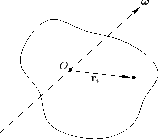
A rigid rotating body
The entire angular momentum of the body (about the origin) is given

Where use has been made of Equation and some standard vector identities.The above formula can be written as a matrix equation of the form

Where


 Here, Ixx is called the moment of inertia about the x-axis, Iyy the moment of inertia about the y-axis, Ixy the xy product of inertia, Iyz the yz product of inertia, etc. The matrix of the Iij values is known as the moment of inertia tensor. Note that individually component of the moment of inertia tensor can be given as either a sum over distinct mass elements or as an integral over infinitesimal mass elements. In the integrals
 where is the mass density, and dV a volume element. Equation can be written more concisely as

Here, it is assumed that L and are both column vectors and  is the matrix of the Iij values. Note that
  is an actual symmetric matrix: i.e.,
  and
and  .
.
In general, the angular momentum vector L obtained from Equation points in a different direction to the angular velocity vector . In further words L is usually not parallel to .
Finally, though the above results were got supposing a stationary angular velocity, they stay valid at each instantaneous in time if the angular velocity varies.
Let's study a simple example that exemplifies the effect of rotation about a non-principal axis. In this case, we consider two masses equal to m1 and m2attached to a rigid massless rod of length 2l aligned from the horizontal by an angle α and rotating around the z axis with constant angular velocity ωk. Let's examine this problem when the bar is aligned with the x and z axes. Due to symmetry, the center of mass is at the origin. Therefore, we only consider the change in angular momentum. Since the magnitude of the angular velocity ω is constant, we are only concerned with its change in direction.
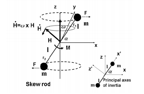
The angular momentum for this classification is H = r × mivi . For this instance, the velocity for mass m1remainsv1=lcosαj, although for mass m2 the velocity is v2 = −ωlcosαj though r1 = lcosαi + lsinαk and r2 = −lcosαi − lsinαk.
At this prompt time, the angular momentum is in the x, z plane and of magnitude
H = −2ml2ωcosαsinαi + 2m l2ωcos2αk
Since the axis about which rotation occurs is not a major axis, it is not surprising that the angular momentum vector is not aligned with the angular velocity vector. In this simple case, since we are dealing with two points of mass, the bar has zero moment of inertia when it rotates about its axis. Therefore, the angular momentum vector is perpendicular to the bar. When the tilt bar rotates around the z axis, the angular momentum changes as
H˙ = ω× H = −2mω2 l2 sinαcosαj
Resulting in a required moment around the y axis to endure the motion of
M = −2mω2 l2 sinαcosαj
This moment has a physical interpretation in terms of centripetal acceleration. As the bar rotates with angular velocity ω, the individual mass points undergo centripetal acceleration directed toward the z axis of
a = −ω2lcosαi.
This needs an external force focused alongside the i direction on m1 a force of
F1 = −ω2 mlcosαi;
On m2, a force of
F2 = ω2mlcosαi ;
Net force is not required because the body is supported at its center of mass. These forces can only be provided / resisted by an external moment applied to the origin, where the rod rests, a moment on the origin of
M = r1 × F1 + r2 × F2 = −2mω2l 2sinαcosαj,
When is the time to support the movement? As the bar rotates around the z axis, it also rotates the moment or torque required to support the movement.
Therefore, any device used to secure the rotating rod to the shaft must support this torque. Note that this force goes to zero for α = 0 and α = π / 2. For these αs, the bar would rotate around a main axis.
References:
1. An Introduction to The Mechanics of Solids, 2nd Ed. With Si Units — Sh Crandall, Nc Dahl & Tj Lardner
2. Engineering Mechanics: Statics, 7th Ed. — Jl Meriam
3. Engineering Mechanics of Solids — Ep Popov