Unit 1
Introduction of Energy Sources and its conversion
- Energy is the capacity for doing work, generating heat, and emitting light.
- The work is the product force and distance.
- Heat is the ability to change the temperature of an object or phase of a substance. For example, heat changes a solid into a liquid or a liquid into a vapor.
- Heat is part of the definition of energy.
- Another part of the definition of energy is radiation, which is the light and energy emitted in the form of waves traveling at the speed of light.
- Units of Energy
- Joule (J) , kilojoule (kJ), in SI System
- Calorie (cal), kilocalorie (kcal) in MKS System.
- 1 kcal = 4.187 kJ
- Power: Power is the rate doing work, which is equal to energy per unit time.
- The units of power are Watt (W), kilowatt (kW), horsepower (hp),
- 1 Watt = 1 joule per second
- 1 Kilowatt = 1,000 Watts = 1000 joule per second
- 1 hp = 746 watt
1.1.1 Forms of Energy
- Thermal Energy: The energy of the substance or the system which is related to its temperature. It is the energy of moving or vibrating molecules of the substance.
- Chemical Energy: Chemical energy is the energy stored in a substance which is related to chemical reaction, usually in the form of heat. Ex. Burning of fuel or gas.
- Electrical Energy: It is a form of energy resulting from the flow of moving electricons in the electrical conductor.
- Mechanical Energy: It is the energy associated with the motion and position of an object. It is the sum of potential energy and kinetic energy.
- Nuclear Energy: It is the energy trapped inside the atom. It is produced by splitting the atom by fission process or by combining the atom by fusion process.
- Gravitational Energy: It is the potential energy of a physical object which is held at some height in the gravitational field.
1.1.2 Grades of Energy
- High grade form of energy:An energy sources (like work or electrical energy) which can be easily converted into all forms of energy is called as High grade form of energy. Ex. Electricity can be converted into heat using Electric heater.
- Low grade form of energy: An energy sources (like heat energy) which cannot be completely converted into work or electrical energy (high grade) is called as Low grade form of energy.
- High grade energy are highly organized in nature and low grade energy are highly random in nature.
- High grade energy is not possible to convert it to low grade energy but low grade energy can be converted into high grade energy.
1.1.3 SOURCES OF ENERGY:
Conventional Energy Sources | Non-Conventional Energy Sources |
Coal, Water, Nuclear Energy, Petroleum Products, Natural gas | Solar, Wind, Ocean, Tidal, Geo-Thermal, etc |
Advantages : Thermal Efficiency is more Initial cost is less. Intensities are high. | Advantages : Easily available in nature. Available in large quantity. Not pollutant, Less maintenance cost. |
Disadvantages : Running and maintenance cost is high Pollution in atmosphere. | Disadvantages : Available in Low intensity. Available in particular period only. Less efficiency of power plant. High initial cost. |
Introduction:
- Thermal power is the largest source of power in India. About 75% of electricity consumed in India is generated by Thermal power plants. There are different types of Thermal power plants based on the fuel used to generate the steam such as coal, gas, diesel etc.
- Thermal power plants are widely used to produce electrical power on large scale.
- Heat energy generated by combustion of fuel is utilized to generate high pressure and high temperature steam in boiler.
- This steam is expanded in steam turbines to produce mechanical power which is finally converted into electrical energy by electric generator.
|
Fig: Block diagram of Energy Conversion in Steam Power Plant
Component of thermal power plant:
- Boiler:
- In thermal Power Plant, a water tube boiler is used to convert water into super-heated steam. Necessary heat in boiler is obtained by combustion of any one of the suitable fuel like coal, oil, natural gas etc.
- Steam Turbine
- High pressure and high temperature steam is expanded in the steam turbine. This produces the shaft work, so the shaft rotates.i.e. Mechanical power is generated in the form of rotation.
- Generator:
- The shaft of the steam turbine is coupled with shaft of generator. Mechanical energy produces by Steam Turbine is converted into Electrical Energy with the help of electric Generator.
- Condenser:
- Low pressure and low temperature steam exhausted from Steam Turbineis cooled and condensed (Conversion of Steam into Water) in condenser by usingcirculated cooling water.
- Feed Pump:
- The collected water (called condensate) is supplied back to boiler ORSteam Generator for steam generation.
- Cooling tower
- Cooling water from cooling tower is circulated into the condenser and it absorb the heat from the exhaust steam of steam turbine. The resultant heated water from condenser is supply at top of the cooling tower.
- This heated water sprayed through the nozzles. It gets cool by cold air passed from bottom of cooling tower. Heated air discharged to the surrounding from the top of cooling tower.
Working of thermal power plant:
- The steam is produced at high pressure in the boiler due to burning of fuel (oil or coal) in boiler furnaces. This steam is further supper heated in a super heater.
- This supper heated steam then enters into the turbine and rotates the turbine blades.
- The turbine is mechanically coupled with generator. So rotor of Generator will rotate with the rotation of turbine blades and produces Electricity.
- After entering in turbine the steam pressure suddenly falls and corresponding volume of the steam increases. After imparting energy to the turbine rotor the steam passes out of the turbine blades into the condenser.
- In the condenser the cold water is circulated with the help of pump which condenses the low pressure wet steam.This condensed water is further supplied back to Boiler where this feed water is again heated & converted in to high pressure steam.
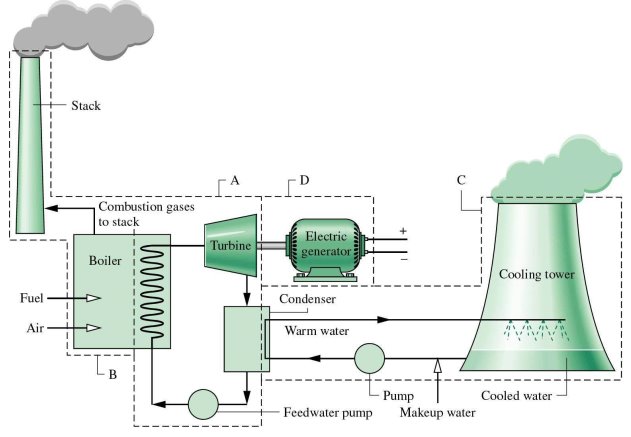
Fig: Schematic diagram of Steam Power Plant.
Advantages
- Fuel is cheaper
- Less space is required as compared with Hydro-electric power plant
- Cheaper in production cost and initial cost compared with diesel power plant
- Transmission Costs are reduced as these plants can be set up near the industry.
Dis-advantages
- The Cost of plant is increases with the increase in temperature and pressure of steam.
- Maintenance and operating cost is high.
- Long Time is required for errection and put in action.
- Large quantity of water is required.
- Coal and ash handling poses a serious problem.
- Pollution causes health problem to workers and habitants near the thermal power plant.
Overall Efficiency of thermal power plant
where,
|
Introduction:
- A nuclear power plant or nuclear power station is a thermal power station in which the heat source is a nuclear reactor. As is typical in all conventional thermal power stations the heat is used to generate steam which drives a steam turbine connected to an electric generator which produces electricity.
- Nuclear power is the large amount of energy that is released innuclear fusionreaction.It is process in which the nucleus of an atom splits into smaller parts (lighter nuclei) and releases a very large amount of energy even by the energetic standards of radioactive decay. The difference in mass between the products and reactants is manifested as the release of large amounts of energy.
Component of nuclear power plant
- The main components of nuclear power plant are:
- Nuclear reactor.
- Steamgenerator (Heat Exchanger)
- Steam turbine.
- Condenser.
- Electric generator.
- Nuclear reactor:
- In nuclear reactor, energy is produced by the fission reaction of nuclear fuel. The nuclear fuels used in nuclear reactor are unstable radioactive materials such as: Thorium (Th 232), Uranium (U 235) or Plutonium (Pu 239)
- In nuclear fission the slow moving neutrons arebombarded on the atoms of nuclear fuel. The heavynucleus of nuclear fuel like uranium is a split into twoor more lighter nuclei having a combined mass lessthan the parent nucleus. The reduced mass is convertedinto enormous energy.
- This energy released is taken away by primarycoolant. The primary coolants may be a gas like:carbon dioxide, helium or liquid metals like: sodium, potassium and their alloys.
- There are three maincomponents of nuclear reactor are: (i) moderator;(ii) control rods; and (iii) external shield.
- (i) Moderator: The fission of nuclear fuel produces fast moving neutrons. These neutrons are sloweddown to right speed by moderators so as toincrease the effectiveness of fission of nuclearfuel.
- (ii)Controlrods: The rate of energy released bychain reaction due to fission of nuclear fuel isvery high. If the rate of heat energy is notcontrolled properly, it may melt the entire coreand the surrounding structures. The rate of heatenergy released is controlled by adjustable rodscalled control rods, made of material likecadmium or boron. The control rods regulate theenergy release by absorbing neutrons. Note thatthe moderator reduces the speed of neutronswithout absorbing them, while the control rodsregulate the energy release by absorbingneutrons.
- (iii)Externalshield: An external shield is providedfor the physical safety of persons operating thenuclear reactor, from harmful effects of radiation.
- Heat Exchanger:
- The heat absorbed by primary coolant in the nuclearreactor is transferred to water in heat exchanger. Thewater is converted into high pressure steam. Thereforethe heat exchanger acts like a boiler of a thermal(steam) power plant.
- Rest of the parts like Steam generator (Heat Exchanger), Steam turbine, Condenser, Electric generator are just like thermal power plant.

Fig: Working of Nuclear power plant.
Working of nuclear power plant:
- When the uranium atom splits, it releases energy and two or more neutrons from its nucleus. These neutrons can then hit the nuclei of other uranium atoms causing them to fission.
- The sequence of one fission triggering others, and those triggering still more, is called a chain reaction when the atoms split, they release energy in the form of heat.
- The heat is transferred from the reactor core to the water flowing past. That water becomes high pressure steam which turns the turbine in the electric generator.
Advantages:
- Large quantity of energy is released by small amount of fuel.
- No combustion products are required
- It is a clean source of power which does not contribute to air pollution.
Disadvantages:
- Its capital cost is high.
- Require trained man power.
- It has a problem of radioactive waste.
- High degree of safety is needed for person working on this plant against the nuclear radiation.
- Cost of power generation is high.
Introduction:
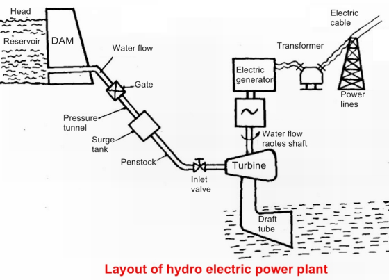
- The potential energy of water is utilized to move the turbines which is turn run the electric generators. It is cleanest methods of producing electric power.
Component of hydroelectric power plant:
- Dam:
- The dam is the most important component of hydroelectric power plant. The dam is built on a large river that has abundant quantity of water throughout the year.
- It should be built at a location where the height of the river is sufficient to get the maximum possible potential energy from water.
- Water Reservoir:
- The water reservoir is the place behind the dam where water is stored. The water in the reservoir is located higher than the rest of the dam structure.
- The height of water in the reservoir decides how much potential energy the water possesses. The higher the height of water, the more its potential energy. The high position of water in the reservoir also enables it to move downwards effortlessly.
- Intake or Control Gates:
- These are the gates built on the inside of the dam. The water from reservoir is released and controlled through these gates. These are called inlet gates because water enters the power generation unit through these gates.
- When the control gates are opened the water flows due to gravity through the penstock and towards the turbines. The water flowing through the gates possesses potential as well as kinetic energy.
- Water Turbines:
- Water flowing from the penstock is allowed to enter the power generation unit, which houses the turbine and the generator.
- When water falls on the blades of the turbine the kinetic and potential energy of water is converted into the rotational motion of the blades of the turbine. The rotating blades cause the shaft of the turbine to also rotate.
- The turbine shaft is enclosed inside the generator. In most hydroelectric power plants there is more than one power generation unit. There are various types of water turbines such as Kaplan turbine, Francis turbine, Pelton wheels etc.
- Generators:
- It is in the generator where the electricity is produced. The shaft of the water turbine rotates in the generator, which produces alternating current in the coils of the generator.
- It is the rotation of the shaft inside the generator that produces magnetic field which is converted into electricity.
Working of Hydroelectric power plant:
|
Fig:Working of hydroelectric power plant.
- The dam stores lots of water behind it in the reservoir. Near the bottom of the dam wall there is the water intake. Gravity causes it to fall through the penstock inside the dam.
- At the end of the penstock there is a turbine propeller, which is turned by the moving water. The shaft from the turbine goes up into the generator, which produces the power.
- Power lines are connected to the generator that carries electricity to your home and mine. The water continues past the propeller through the tailrace into the river past the dam.

Advantages:
- Operation cost is less.
- More reliable.
- Starting and stopping of these plants takes short time compared with Steam Power Plant.
- It has no ash disposal problem and nuclear waste disposal problem.
- Required less supervising staff.
- These plants can be used for irrigation and flood control purposes in addition to power generation.
Disadvantages:
- The total power developed depends upon the availability of water and hence these are dependent on rainfall.
- These plants are usually away from the place needing electric power, hence cost of transmission lines increases.
- Time required for development of such plant is high.
Overall Efficiency of Hydro Electric power plant
 (Watt)
where,  Density (kg/m3)
 Discharge or Volume flow rate (m3/Sec)
 Available head of water in Meters

Introduction:
- Wind can be used as a power source. Wind power is the use of air flow through wind turbines to mechanically power generators for electricity.
- Wind power, as an alternative to burning fossil fuels, is plentiful, renewable, widely distributed, clean, produces no greenhouse gas emissions during operation, consumes no water, and uses little land.
- The net effects on the environment are far less problematic than those of nonrenewable power sources.
- The wind power can be generated where the wind velocities are more than 8 kmph.
- Such winds are available along the sea coast and at high altitudes in hilly region.
- The wind power is clean and non-polluting
- It has low maintenance cost and low power generation cost of about Rs. 2.25/kWh.
- It needs high capital cost of about 3.5crores/MW.
Construction andWorking of wind power plant:
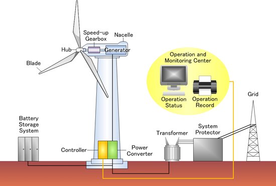
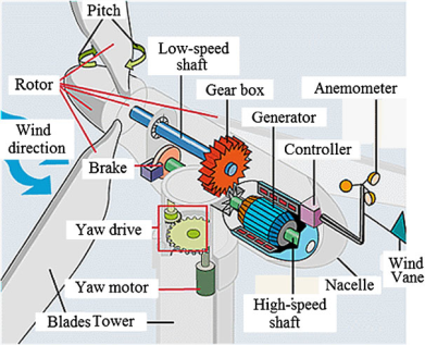
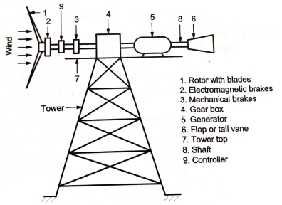
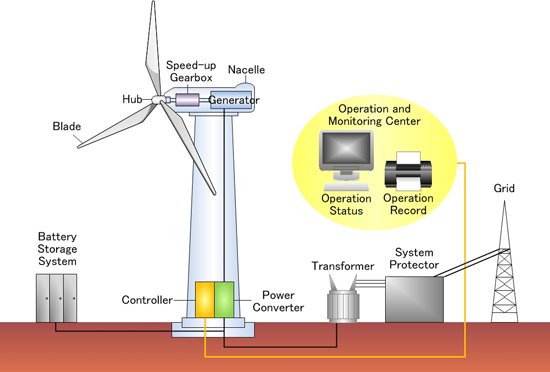
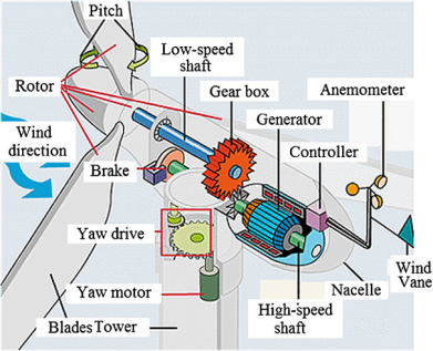
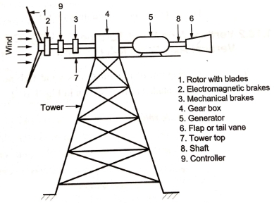
- It consists of rotor blade, Gear box, generator, power cables, tower and transformer. The blade is attached or connected to the nacelle.
- The gear box is present inside the assembly and generator is connected to it. Through the generator cables are connected and supplied to directly the power supply system.
|
|
|

- Wind (moving air that contains kinetic energy) blows toward the turbine's rotor blades. The rotors spin around, capturing some of the kinetic energy from the wind, and turning the central drive shaft that supports them.
- Although the outer edges of the rotor blades move very fast, the central axle (drive shaft) they're connected toturbine turns quite slowly.
- The gearbox converts the low-speed rotation of the drive shaft into high-speed rotation fast enough to drive the generator. The generator, immediately behind the gearbox, takes kinetic energy from the drive shaft and convert it into electrical energy.
Advantages:
- Non-polluting.
- No fuel is required.
- The cost of generation is low.
Dis-advantages:
- More noisy.
- Weight of system is high.
- Does not provide constant output due to velocity fluctuations.
Overall Efficiency of Hydro Electric power plant


where,  Density of air (kg/m3)
A = Area of wind Turbine (m2)
D = Diameter of wind Turbine (m)
V = Wind Velocity (m/sec)

Introduction
- Solar energy is energy that is in sunlight. It has been used for thousands of years in many different ways by people all over the world.
- As well as its traditional human uses in heating, cooking, and drying, it is used today to make electricity where other power supplies are absent, such as in remote places and in space.
- It is becoming cheaper to make electricity from solar energy and in many situations it is now competitive with energy from coal or oil.
- The sun is producing solar energy through nuclear fusion. In this reaction, two atoms, deutorium (heavy hydrogen) combines to form one atom of helium and during the process if releases large amount of energy which reaches the earth's surface through electromagnetic radiation.
- The sun sends out the energy in the form of radiations at the rate of 3.7 x 10²⁰ MW. However, the energy reached to the earth is about 1.85 x 10¹¹ MW. This energy available is several times more than all the energy produced and consumed in the world today.
Advantages of Solar Energy
- It can be directly converted into electrical energy using photo-voltaic cells.
- Available in abundance.
- Renewable and inexhaustible source of energy.
- Free from pollution.
- It has low operating and maintenance cost.
- No fossil fuels are needed.
- No arrangements are needed for transportation handling and storage of fuels as needed in conventional power plants.
Limitations of Use of Solar Energy
- This energy is dilute and spread out.
- The average power obtainable is only 1 kW/m2 of area in hottest regions. Therefore, large collection area is required.
- The intensity of radiation is weather dependent.
- It is intermittent source of energy since it is not available at night.
- Seasonal variations affects the intensity of radiation.
- The requirement of energy storage devices are heavy in order to cater the energy during the hours of non-availability of solar energy.
Solar collectors
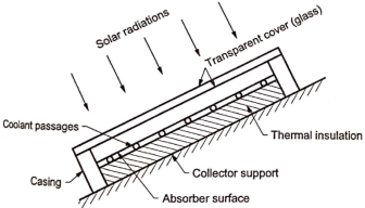
- It is a device for collecting or absorbing the solar radiations on a surface called absorber. Then, Transfer of radiant energy to fluid like water or air in contact with collector takes place. The surface of the collector is designed for high absorption and low emissions.
- Types of Solar Collectors
- Flat plate collectors
- Concentrating type of collectors
- Flat plate collectors
|
- These collectors are used for low temperature applications in the range from room temperature upto 100°C.
- If the working fluid absorbing the heat is liquid, then such collectors are also called as liquid flat plate collectors.
- Flat plate collectors are used for low temperature applications like solar water heating, space heating and cooling, drying, low temperature power generation etc.
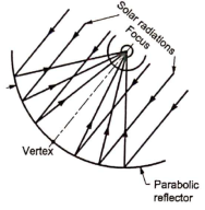
2. Concentrating type of collectors
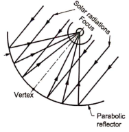
- The cross-section Concentrating type of collector is shown in Fig.
- These collectors are also called as focusing collectors. These are used for medium to high temperature applications.
- These collectors are of two types: (a) Cylindrical parabolic collectors (b) Parabolloid mirror arrays
- (a) Cylindrical parabolic collectors: These types of solar collectors are suitable for application in the range of 100°C to 300°C. These collectors are used for vapour engines and turbines, process heating in industry, refrigeration, cooking etc.
- (b) Parabolloid mirror arrays:
|
These types of solar collectors are used for production of temperatures above 300°C. These are suitable for thermo-electric power generation.
Power generation from solar energy
- Solar Thermal Power Plants
- Solar PV Cell Power Plants
- Construction and working of SOLAR THERMAL POWER PLANT
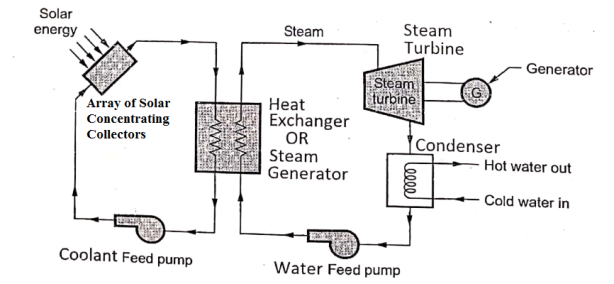
- It consists of array of concentrating solar collectors, steam generator or Heat Exchanger, steam turbine, condenser and generator as shown in figure. The generator attached to the steam turbine.
|
Fig: Construction and working of solar thermal power plant.
- Concentrating solar collectors are used to produce high pressuresteam which is then used in the conventional steam power plants.
- Solar collectors capture and concentrate sunlight to heat liquid inside the collector, which then heats water in the heat exchanger to create steam. The steam is piped to an onsite turbine-generator to produce electricity.
1.6.2 Construction and working of SOLAR PV-CELL POWER PLANT
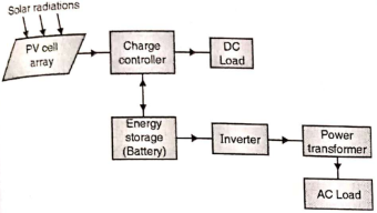
|
Solar Photovoltaic (PV) Cell Power Plant
- Solar PV cells generate electricity by absorbing sunlight and using that light energy to create an electrical current. These solar cells are connected in series/parallel array to produce large power output.
- Photovoltaic cells, through the photovoltaic effect, absorb sunlight and generate flowing electricity.
- Step 1: Light is absorbed by the PV cell and knocks electrons loose. First, light strikes a photovoltaic cell and is absorbed by the semiconducting material which is made from (usually silicon). This incoming light energy causes electrons in the silicon to be knocked loose.
- Step 2: Electrons begin to flow, creating an electrical current. There are two layers of silicon used in photovoltaic cells, and each one is specially treated, or “doped”, to create an electric field, meaning one side has a net positive charge and one has a net negative charge. This electric field causes loose electrons to flow in one direction through the solar cell, generating an electrical current.
- Step 3: The electrical current is captured and combined with other solar cells. Once an electrical current is generated by loose electrons, metal plates on the sides of each solar cell collect those electrons and transfer them to wires. At this point, electrons can flow as electricity through the wiring to a solar inverter and then throughout your home.
- Thus DC Electricity is produced. It is supplied to battery through charge controller. DC power can be converted in AC by using an inverter to take up AC loads.
- Function of Charge Controller: During non-sunshine hours, the current can flow from battery to charge controller but it does not allow the current to flow back to PV cells. Therefore it avoids the damage to PV cells.
- Geothermal energy in the form of thermal energy is a form of renewable source of energy having high energy density. It is renewable since the earth's interior will continue to provide energy continuously in the process of cooling of earth's interior.
- It is inexhaustible like solar or wind energy. The geothermal energy in the form of heat energy can be utilized economically and efficiently for power generation and other applications with the existing available technologies.
- Geothermal energy or earth's heat manifests itself on the earth's surface in the following forms:
- Hot water springs.
- The geysers (hot water and steam) and fumaroles (hot steam and hot gases) released periodically in the volcanic region or geothermal fields.
- Volcanic eruptions of geothermal energy in the large quantities released in the form of hot lava, rocks, boiling mud etc.
- Generally the thermal energy available inside the earth is at a depth of more than 80 km. However, there are few locations in the world where this energy can be extracted at a depth of 0.3 km to 3 km called geothermal fields.
Advantages of Geothermal Energy
- It is reliable source of energy which is available continuously throughout the year.
- It is independent of weather conditions.
- No thermal storage facility is required.
- Capital and generation cost is low as compared to conventional thermal power plants.
- No solid pollutants.
- Needs very small land area.
Disadvantages of Geothermal Energy
- It is a low grade heat energy since the temperatures are limited to 150° C.
- Parts of plant may corrode due to presence of salt.
- Geothermal fluids also bring in dissolved gases like H2S, CO2,NH3 gases and other solute which causes air pollution and land pollution if effluent is not discharged into ground.
- Life of plant is low compared to conventional power plants due to corrosive and abrasive geothermal fluids.
- Continuous extraction of fluid may cause settlement of land.
- Causes noise pollution due to exhausts, centrifugal separators, blow down etc. Thus, silencers are needed on some of installed Equipments.
Applications of Geothermal Energy
- Space heating and cooling
- Generation of electrical power
- Industrial process heat, desalination of water, heavy water production, extraction of minerals from geothermal fluids, timber seasoning etc.
1.7.1 Binary Cycle Power Plant (Geo-thermal Power Plant)
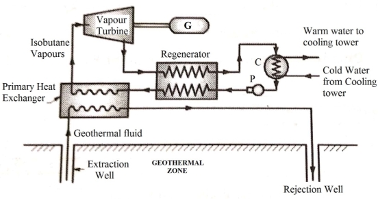
- The geothermal resources are available in the temperature range of 90° C to 170° C. This temperature is not sufficient for production of two phase mixture of steam.
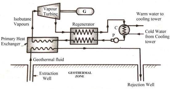
- The system of Binary Cycle Power Plant is shown in Figure.
- In order to utilize this geothermal heat, fluid of low boiling temperature like isobutane is used under pressure in a primary heat exchanger.
|
- Geothermalfluid extracted from earth crust is sent to primary heat exchanger where it transfers the heat to isobutane. Thus Vapour of isobutane are generated and is passed through a turbine where it is expanded. The mechanical power of turbine is utilized to produce the electricity by a generator.
- Exhaust vapour of the turbine is passed through aregenerator (heat exchanger) where it gives the heat to the condensate coming from condenser. This Cooled exhaust is then
condensed in the condenser. The returned condensate is heated in the regenerator by exhaust vapour of the turbine. - The geothermal fluid is re-injected after extracting heat in to the ground.
- Hydrogen is the simplest element. An atom of hydrogen consists of only one proton and one electron. It’s also the most plentiful element in the universe. Hydrogen as an alternative fuel since hydrogen is available in abundance in water.
- It reduces the environmental pollution caused by the use of conventional fuels.
- Despite its simplicity and abundance, hydrogen doesn’t occur naturally as a gas on the Earth-it’s always combined with other elements.
- Also, hydrogen provides a large amount of energy on combustion compared to petrol and diesel. It mixes very easily with air and it can burn 4 % lean mixture to 75 % rich mixtures on volume basis.
- H2 can be produced by electrolysis but this method is very expensive.
- H2 is also available as by product from chemical industries like caustic soda and its cost of production is quite comparable with petrol.
- Practical problem in using it, as fuel is due to its high explosive nature on combustion and development of high flame speeds in engines.
- H2 is used as fuel for power generation in fuel cells.
1.8.1 Hydrogen-Oxygen (H2-O2) Fuel Cell
- A fuel cell is an electro-chemical device in which the chemical energy of fuel is continuously converted into electric energy. This conversion of energy takes place at constant pressure and temperature.
- The main components of a fuel cell are:
- A fuel electrode (anode)
- An oxidant electrode (cathode)
- An electrolyte (solution of H2SO4 for acidic fuel cell, KOH for alkali fuel cells)
- container, separators, sealing, fuel and oxidant supply etc.
- The basic feature of a fuel cell is that the fuel and the oxidant are combined in the form of ions than in form of neutral molecules.
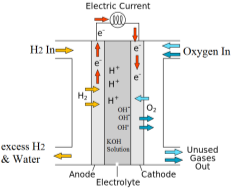
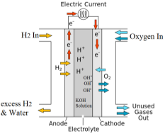
- Figure showsthe schematic diagram of a fuel cell using hydrogen as fuel and oxygen as oxidant and alkaline solution of KOH as electrolyte.
- It is called alkaline fuel cell (AFC). It consists of two permeable Nickel electrodes immersed in an electrolyte of good conductivity.
- The porous fuel electrode is anode (negative pole) and the other porous oxidant electrode is cathode (positive pole) are separated by a porous gas barrier. The anode is supplied H2gas as fuel at a certain pressure and the cathode is supplied O2 as oxidant at a pressure.
|
- These gases pass through the respective electrodes and bubble around through the electrolyte solution. Thus gases, electrodes and electrolyte come in contact for their electrochemical reactions. The electrodes are connected through an external circuit.
- The electro-chemical reactions are generally slow and a catalyst is required in the electrodes to accelerate the reaction.
- The hydrogen gas is ionized at anode and it produces a free electron and H+ ions. The reaction at anode is as follows:

- The oxygen supplied to cathode (positive electrode) reacts with water of electrolyte and the electrons transmittedto it to produce hydroxyl (OH) ions. Thus,

- These hydroxyl ions migrate from cathode to anode through electrolyte. The hydrogen and hydroxyl ions then combine in the electrolyte to produce water i.e.

- By adding the above three equations, the overall process is chemical reaction of H2 and O2 gases toform water i.e.

- Thus the net reaction of a fuel cell in which hydrogen and oxygen supplied is the produce water, electrical energy and heat.
Advantages of Fuel Cell
- Conversion efficiencies are very high.
- Require little attention and less maintenance.
- Fuel cell does not make any noise.
- Can be installed near the use point, thus reducing electrical transmission requirements and accompanying losses.
- A little time is needed to go into operation.
- Space requirement considerably less in comparison to conventional power plants.
Disadvantages of Fuel Cell
- High initial cost.
- Low service life.
Definition of Biomass
- Biomass is an organic matter produced by plants both grown on land and grown on water their derivatives and animal manure. The energy obtained from biomass is called biomass energy.
- Coal, petroleum oil and natural gas do not come in the category of 'biomass', because they are produced from dead, buried biomass under pressure and temperature during millions of year. Biomass can also be considered a form of solar energy as the latter is used indirectly to grow these plants by photosynthesis.
Classification of Biomass Resources
- Concentrated wastes
(i) Municipal solid (ii) Sewage wood products (iii) Industrial waste (iv) Manure at large lots.
- Dispersed waste residue: (i) Crop residue (ii) Logging residue (iii) Disposed manure.
- Harvested biomass : (i) Standing biomass (ii) Biomass energy plantations.
1.9.1 Biomass Energy Conversion Process
Direct combustion:
- Combustion is the process of burning in presence of oxygen to produce heat, light and byproducts. Complete combustion to ashes is called incineration.
- Various designs of boilers and furnaces are available to burn biomass like wood, dung, dried vegetable wastes from food industry, pulp, bagasse from sugar industry and municipal wastes etc.
- The moisture content in biomass and their wide range of composition tends to produce low calorific value of fuel.
- However, if biomass energy by combustion is used as co-generation with conventional fuels, the utilization of biomass energy makes it an attractive proposition.
Thermo Chemical Conversion
- These processes can be carried out in following ways.
- Gasification:
- Heating of biomass in presence of limited oxygen and air (deficient O2/air) is called gasification. It produces gaseous fuels like H2, CO, CH4, N2 of low calorific value.
- Pyrolysis:
- It is the heating of biomass in a closed vessel at temperatures in the range of 500°C — 900°C in absence of O2/air or with steam.
- It produces solid, liquids and gases.The pyrolysis process can use all type of organic materials including plastic and rubbers.The gases produced by this process include the mixture of CO, CH4, N2, H2, CO2 and other hydrocarbons.
- The liquids produced are oil like materials (acetic acid, methanol, oil and tar) and solids produced are similar to pure carbon charcoal.
Biochemical Conversion
- The process of biochemical conversion of biomass makes use of metabolic action of microbial organism on biomass to produce liquid and gaseous fuels. These processes are of two types: Fermentation of Biomass and Anaerobic Digestion of Biomass
- Fermentation:
- It is a process of decomposition of complex molecules of organic compound under the influence of micro-organism (ferment) such as yeast, bacteria. enzymes etc.
- The example of fermentation process is the conversion of grains and sugar crops into ethanol and CO, in presence of yeast. 10% of ethanol so produced can be blended with petrol to produce gasohol.
- Anaerobic Digestion of Biomass:
- This process involves the conversion of decaying wet biomass and animal wastes into biogas through decomposition process by the action of anaerobic bacteria.
- The anaerobic bacteria is a micro-organism that can live and grow in absence of O2 or air. For example the production of biogas from human and animal wastes, the decomposition of biomass like sewage sludge, green plants etc.
- The gas produced is mixture of methane (55% to 70%) and remainder is CO, with other impurities.
- The most useful biomass for production of biogas are animal and human waste, algae, hyacinth, plant residue and other organic waste materials with high moisture content.
- The periodic rise and fall of the water level of sea which are carried by the action of the sun and moon on water on, earth is called the 'tide'.
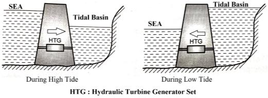
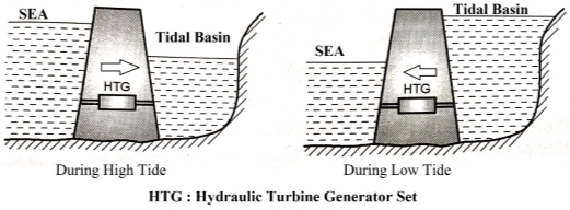
- The main feature of the tidal cycle is the difference in water surface elevations at the high tide and at the low tide. If this differential head could be utilized in operating a hydraulic turbine, the tidal energy could be converted into electrical energy by means of an attached generator.
|
- Figure shows a general arrangement of single basin tidal power plant (double cycle system). Such plants generally use reversible water turbines so that power is generated on low tide as well high tide. The operation of the plant is as follows.
- When the incoming tide sea level and tidal-basin level are equal, the turbine conduit is closed. When the sea level rises, and about half way to high tide the turbine valves are opened and the sea water flows into the basin through the turbine runner generating power.
- This also raises the level of water in the basin. The turbine continues to generate power until the tide passes through its high point and begins to drop.
- When sea and basin water level are again equal, the valves are closed as well as the turbine conduit. The basin level then stays constant while the tide continues to go out. After sufficient head has developed, the turbine valves are again opened and water now from basin to the sea, thereby generating power.
Advantages
- Inexhaustible source
- Low space is needed.
- Pollution free.
Disadvantages
- Due to variation in tide output is not uniform.
- Plant efficiency is variable.
- Higher cost.
- Difficult to install in sea.
- Pump is an apparatus or machine used for raising, driving, exhausting, or compressing fluids or gases by means of a piston, plunger, or set of rotating vanes.
- Pumps are in general classified as Reciprocating pumps or Positive Displacement Pumps and Centrifugal Pumps.
- Centrifugal Pump:
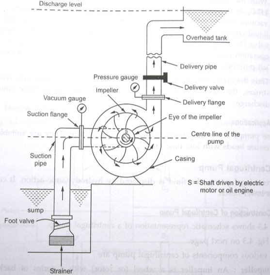
- A centrifugal pump is a device or equipment which converts kinetic energy to pressure energy by a rotating impeller.
- Centrifugal pump works on the principle that when a certain mass of liquid is made to rotate along the impellerabout the central axis of rotation, a centrifugal head is
imparted to liquid. It causes the liquid to move radiallyoutwards at higher velocity.This velocity head is converted in to pressure head in casing. - The simplest explanation is then can be written as a device which generates an increase in pressure of the fluid by transferring mechanical energy of motor to the fluid by the action of rotating impeller.
- The fluid flows from the inlet to the suction eye or the impeller centre and out along the vanes. The kinetic energy from the rotating impeller is transferred to the water in the form of its pressure energy thus increases pressure Head.
|
Constructionof Centrifugal Pump:
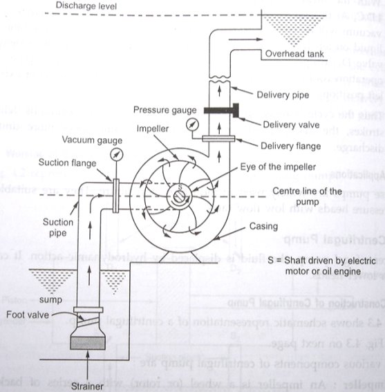
- Impeller: An impeller is a wheel or rotor having a series of backward curved vanes or blades. The impeller ismounted on a shaft which is usually coupledto a motor. The motor provides the required input energy to rotate the impeller.
- Casing: The impeller is enclosed in a watertight casing with delivery pipe on one side and with an arrangement onsuction side called eye of impeller. Casing has to perform two functions: (a) it guides the water from entry to exit of impeller, (b) the casing is so designed that it helps in partly converting the kinetic energy of the liquid into pressure energy.
- Suction pipe:The pipe which connects the sump to the eye of impeller is called as Suction pipe. The sump carries the liquid to be lifted by the pump.
- Strainer and foot valve: The suction pipe at its inlet is provided with a strainer and a fool valve.The function of strainer is to prevent the entry of any debris into the pump. The foot valve is a non-return valve which allows the flow of water only in upward direction.
- Delivery pipe: The pipe which connects the outlet of pump to delivery point is called delivery pipe. A valve is provided in the delivery pipe near the outlet of the pump called delivery valve. Its function is to regulate the supply of liquid from the pump to delivery Pipe.
Working of Centrifugal Pump:
- The steps involved in operation of centrifugal pump are as follows
- The delivery valve is closed. The priming of the pump is carried out. Priming involves the filling the liquid in suction pipe and casing upto the level of delivery valve so that no air pockets are left in the system.
- The pump shaft and impeller is now rotated with the help of prime mover, like electric motor. The rotation of impeller inside a casing full of liquid produces a forced vortex which is responsible in imparting the centrifugal head to the liquid.
- It creates a vacuum at the eye of impeller and causes liquid to rise into suction pipe from the sump.
- Now the delivery valve is opened and the liquid is lifted and discharged through the delivery pipe due to its high pressure. Thus the liquid is continuously sucked from the sump to impeller eye and it is delivered from the casing of pump through the delivery pipe.
- A machine that extracts air from the atmosphere and compresses it into a holding chamber.
- Air Compressor- is used to compress the atmospheric air to high pressure.
- The three basic types of air compressors are
- Reciprocating
- Rotary screw
- Rotary centrifugal
- Reciprocating Compressor:
- Reciprocating air compressors are positive displacement machines, meaning that they increase the pressure of the air by reducing its volume.
- This means they are taking in successive volumes of air which is confined within a closed space and elevating this air to a higher pressure.
- The reciprocating air compressor accomplishes this by a piston within a cylinder as the compressing and displacing element.
- The reciprocating air compressor is single acting when the compressing is accomplished using only one side of the piston. A compressor using both sides of the piston is considered double acting.
- Construction
- The reciprocating type compressor consists of a piston which is enclosed within the cylinder & equipped with suction & discharge valves.
- The piston receives power from main shaft through crankshaft and connecting rod. A flywheel/belt wheel is fitted on the crankshaft which is driven by electric motor or diesel engine. It supplies uniform motion throughout the cycle of operations.
1.12.1.2 Working:
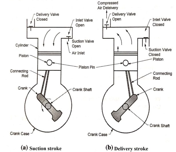
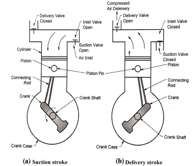
- The compression of air is done by first drawing a volume of air into its cylinder through suction valves during suction stroke by the piston & then compressing & discharging it on the return stroke of the piston through delivery valves.
- This simple working is used in every Reciprocating Air Compressor.
|
Fig: Suction and Delivery Stroke of a Reciprocating Air Compressor
- In single stage reciprocating air compressor the entire compression is carried out in a single cylinder. If the compression is affected in one end of the piston & cylinder then it is known as single acting & if the compression is affected in both ends of piston & cylinder then it is known as double acting reciprocating air compressor.
1.12.1.3 Application of Compressed Air:
- Inflating tyres /tubes
- In spray Paintings
- For cleaning purposes in garages along with water for washing cars etc.
- Gas turbines
- Diesel Engines, Air Brakes
1.13.1 Introduction
- A turbine is a turbo machine with at least one moving part called a rotor assembly, which is a shaft or drum with blades attached. Moving fluid acts on the blades so that they move and impart rotational energy to the rotor.
1.13.2 Impulse Turbine
|
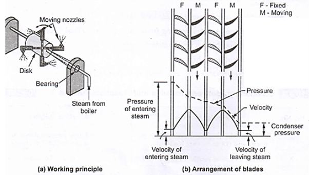
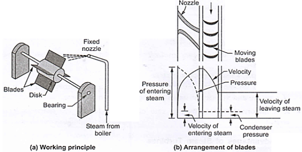
Fig: Impulse Turbine working principle
- The steam jets are directed at the turbine's bucket shaped rotor blades where the pressure exerted by the jets causes the rotor to rotate and the velocity of the steam to reduce as it imparts its kinetic energy to the blades.
- The blades in turn change the direction of flow of the steam however its pressure remains constant as it passes through the rotor blades since the cross section of the chamber between the blades is constant.
- Impulse turbines are therefore also known as constant pressure turbines. The next series of fixed blades reverses the direction of the steam before it passes to the second row of moving blades.
- If a jet of steam is discharged from a fixed nozzle at a high speed over a flat stationary plate, a steady force will be exerted over this plate. This force is nothing but an impulse.
- No work is done as the plate is fixed. But, if a number of such plates are fixed on the rim of a wheel, the wheel may be rotated due to the impulse of steam. Curved plates are used instead of flat plates to utilize greater amount of energy.
- In the impulse turbine, steam is expanded in the fixed nozzle only. In the nozzle the velocity of steam increases with decrease of pressure. As the steam passes over the blades, the pressure remains constant with a decrease of velocity.
1.13.3 Reaction Turbine:
- A reaction turbine is a type of turbine that develops torque by reacting to the pressure or weight of a fluid; the operation of reaction turbines is described by Newton's third law of motion (action and reaction are equal and opposite).
|
Fig: Reaction Turbine working principle
- The rotor blades of the reaction turbine are shaped more like aerofoils, arranged such that the cross section of the chambers formed between the fixed blades diminishes from the inlet side towards the exhaust side of the blades.
- The chambers between the rotor blades essentially form nozzles so that as the steam progresses through the chambers its velocity increases while at the same time its pressure decreases, just as in the nozzles formed by the fixed blades.
- Thus the pressure decreases in both the fixed and moving blades. As the steam emerges in a jet from between the rotor blades, it creates a reactive force on the blades which in turn creates the turning moment on the turbine rotor, just as in steam engine. (Newton's Third Law - For every action there is an equal and opposite reaction).
- In a reaction turbine, the blades sit in a much larger volume of fluid and turn around as the fluid flows past them. A reaction turbine doesn't change the direction of the fluid flow as drastically as an impulse turbine: it simply spins as the fluid pushes through and past its blades. Wind turbines are perhaps the most familiar examples of reaction turbines.
1.13.4 Difference between impulse and reaction turbine
Impulse Turbine | Reaction Turbine |
In this turbine all the pressure energy is converted into KE. | Some amount of pressure energy is converted into KE. |
Steam is expanded completely in nozzle. | Steam is partially expanded in nozzle. |
Less efficiency | High efficiency |
Suitable for small power requirement. | Suitable for medium and large power requirement. |
Occupy less space | Occupy more space |
High rotor speed. | Low rotor speed. |
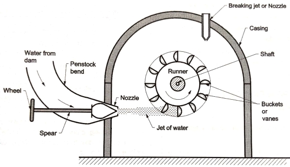
1.14.1 Working
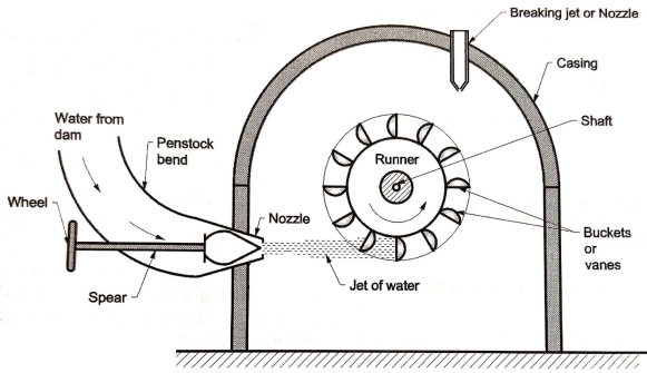
- Impulse turbine works on the basic principle of impulse. When the jet of water strikes at the turbine blade with full of its speed, it generates a large force which used to rotate the turbine.
- The force is depends on the time interval and velocity of jet strikes the blades.
- This turbine used to rotate the generator, which produces electric power. High pressure water flow form dam (high head) to nozzle (low head).
|
- This water flows through divergent nozzle where it’s all pressure energy change into kinetic energy. It forms a water jet.
- The water jet strikes the blade at high speed which rotates the rotor.It transfers all kinetic energy of water to the rotor, which further use to rotate the generator.
- After transferring energy, water flows to the tail race.This process run continuously until sufficient power generates.
Reference Books
1. Khan, B. H., “Non Conventional Energy Sources, Tata McGraw-Hill Publisher Co. Ltd.
2. Boyle, Godfrey, “Renewable Energy”,2nd Ed., Oxford University Press
3. Khurmi, R.S. ,and Gupta, J. K.,“A Textbook of Thermal Engineering”, S. Chand & Sons
4. Incropera, F. P. and Dewitt, D.P., (2007), “Fundamentals of Heat and Mass Transfer, 6th Ed., John Wiley and Sons, USA
5. Groover,Mikell P., (1996), “Fundamentals of Modern Manufacturing: Materials, Processes, and Systems”, Prentice Hall, USA
6. Norton, Robert L., (2009), “Kinematics and Dynamics of Machinery”, Tata McGrawHill
7. Cleghorn, W. L., (2005), “Mechanisms of Machines”, Oxford University Press
8. Juvinal, R. C., (1994), “Fundamentals of Machine Component Design”, John Wiley and Sons, USA
9. Ganeshan, V., (2018), “Internal Combustion Engines”, McGraw Hill
10. Anderson, Curtis Darrel and Anderson,Judy, (2010), “Electric and Hybrid Cars: A History”, 2nd Ed., McFarland
Unit 1
Introduction of Energy Sources and its conversion
- Energy is the capacity for doing work, generating heat, and emitting light.
- The work is the product force and distance.
- Heat is the ability to change the temperature of an object or phase of a substance. For example, heat changes a solid into a liquid or a liquid into a vapor.
- Heat is part of the definition of energy.
- Another part of the definition of energy is radiation, which is the light and energy emitted in the form of waves traveling at the speed of light.
- Units of Energy
- Joule (J) , kilojoule (kJ), in SI System
- Calorie (cal), kilocalorie (kcal) in MKS System.
- 1 kcal = 4.187 kJ
- Power: Power is the rate doing work, which is equal to energy per unit time.
- The units of power are Watt (W), kilowatt (kW), horsepower (hp),
- 1 Watt = 1 joule per second
- 1 Kilowatt = 1,000 Watts = 1000 joule per second
- 1 hp = 746 watt
1.1.1 Forms of Energy
- Thermal Energy: The energy of the substance or the system which is related to its temperature. It is the energy of moving or vibrating molecules of the substance.
- Chemical Energy: Chemical energy is the energy stored in a substance which is related to chemical reaction, usually in the form of heat. Ex. Burning of fuel or gas.
- Electrical Energy: It is a form of energy resulting from the flow of moving electricons in the electrical conductor.
- Mechanical Energy: It is the energy associated with the motion and position of an object. It is the sum of potential energy and kinetic energy.
- Nuclear Energy: It is the energy trapped inside the atom. It is produced by splitting the atom by fission process or by combining the atom by fusion process.
- Gravitational Energy: It is the potential energy of a physical object which is held at some height in the gravitational field.
1.1.2 Grades of Energy
- High grade form of energy:An energy sources (like work or electrical energy) which can be easily converted into all forms of energy is called as High grade form of energy. Ex. Electricity can be converted into heat using Electric heater.
- Low grade form of energy: An energy sources (like heat energy) which cannot be completely converted into work or electrical energy (high grade) is called as Low grade form of energy.
- High grade energy are highly organized in nature and low grade energy are highly random in nature.
- High grade energy is not possible to convert it to low grade energy but low grade energy can be converted into high grade energy.
1.1.3 SOURCES OF ENERGY:
Conventional Energy Sources | Non-Conventional Energy Sources |
Coal, Water, Nuclear Energy, Petroleum Products, Natural gas | Solar, Wind, Ocean, Tidal, Geo-Thermal, etc |
Advantages : Thermal Efficiency is more Initial cost is less. Intensities are high. | Advantages : Easily available in nature. Available in large quantity. Not pollutant, Less maintenance cost. |
Disadvantages : Running and maintenance cost is high Pollution in atmosphere. | Disadvantages : Available in Low intensity. Available in particular period only. Less efficiency of power plant. High initial cost. |
Introduction:
- Thermal power is the largest source of power in India. About 75% of electricity consumed in India is generated by Thermal power plants. There are different types of Thermal power plants based on the fuel used to generate the steam such as coal, gas, diesel etc.
- Thermal power plants are widely used to produce electrical power on large scale.
- Heat energy generated by combustion of fuel is utilized to generate high pressure and high temperature steam in boiler.
- This steam is expanded in steam turbines to produce mechanical power which is finally converted into electrical energy by electric generator.
|
Fig: Block diagram of Energy Conversion in Steam Power Plant
Component of thermal power plant:
- Boiler:
- In thermal Power Plant, a water tube boiler is used to convert water into super-heated steam. Necessary heat in boiler is obtained by combustion of any one of the suitable fuel like coal, oil, natural gas etc.
- Steam Turbine
- High pressure and high temperature steam is expanded in the steam turbine. This produces the shaft work, so the shaft rotates.i.e. Mechanical power is generated in the form of rotation.
- Generator:
- The shaft of the steam turbine is coupled with shaft of generator. Mechanical energy produces by Steam Turbine is converted into Electrical Energy with the help of electric Generator.
- Condenser:
- Low pressure and low temperature steam exhausted from Steam Turbineis cooled and condensed (Conversion of Steam into Water) in condenser by usingcirculated cooling water.
- Feed Pump:
- The collected water (called condensate) is supplied back to boiler ORSteam Generator for steam generation.
- Cooling tower
- Cooling water from cooling tower is circulated into the condenser and it absorb the heat from the exhaust steam of steam turbine. The resultant heated water from condenser is supply at top of the cooling tower.
- This heated water sprayed through the nozzles. It gets cool by cold air passed from bottom of cooling tower. Heated air discharged to the surrounding from the top of cooling tower.
Working of thermal power plant:
- The steam is produced at high pressure in the boiler due to burning of fuel (oil or coal) in boiler furnaces. This steam is further supper heated in a super heater.
- This supper heated steam then enters into the turbine and rotates the turbine blades.
- The turbine is mechanically coupled with generator. So rotor of Generator will rotate with the rotation of turbine blades and produces Electricity.
- After entering in turbine the steam pressure suddenly falls and corresponding volume of the steam increases. After imparting energy to the turbine rotor the steam passes out of the turbine blades into the condenser.
- In the condenser the cold water is circulated with the help of pump which condenses the low pressure wet steam.This condensed water is further supplied back to Boiler where this feed water is again heated & converted in to high pressure steam.
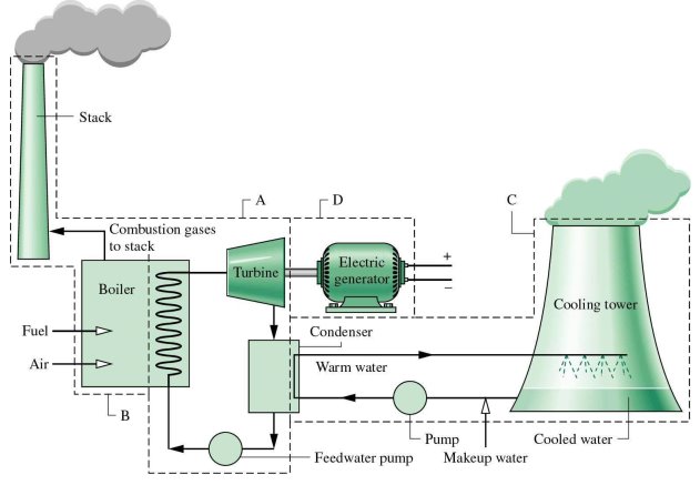
Fig: Schematic diagram of Steam Power Plant.
Advantages
- Fuel is cheaper
- Less space is required as compared with Hydro-electric power plant
- Cheaper in production cost and initial cost compared with diesel power plant
- Transmission Costs are reduced as these plants can be set up near the industry.
Dis-advantages
- The Cost of plant is increases with the increase in temperature and pressure of steam.
- Maintenance and operating cost is high.
- Long Time is required for errection and put in action.
- Large quantity of water is required.
- Coal and ash handling poses a serious problem.
- Pollution causes health problem to workers and habitants near the thermal power plant.
Overall Efficiency of thermal power plant
where,
|
Introduction:
- A nuclear power plant or nuclear power station is a thermal power station in which the heat source is a nuclear reactor. As is typical in all conventional thermal power stations the heat is used to generate steam which drives a steam turbine connected to an electric generator which produces electricity.
- Nuclear power is the large amount of energy that is released innuclear fusionreaction.It is process in which the nucleus of an atom splits into smaller parts (lighter nuclei) and releases a very large amount of energy even by the energetic standards of radioactive decay. The difference in mass between the products and reactants is manifested as the release of large amounts of energy.
Component of nuclear power plant
- The main components of nuclear power plant are:
- Nuclear reactor.
- Steamgenerator (Heat Exchanger)
- Steam turbine.
- Condenser.
- Electric generator.
- Nuclear reactor:
- In nuclear reactor, energy is produced by the fission reaction of nuclear fuel. The nuclear fuels used in nuclear reactor are unstable radioactive materials such as: Thorium (Th 232), Uranium (U 235) or Plutonium (Pu 239)
- In nuclear fission the slow moving neutrons arebombarded on the atoms of nuclear fuel. The heavynucleus of nuclear fuel like uranium is a split into twoor more lighter nuclei having a combined mass lessthan the parent nucleus. The reduced mass is convertedinto enormous energy.
- This energy released is taken away by primarycoolant. The primary coolants may be a gas like:carbon dioxide, helium or liquid metals like: sodium, potassium and their alloys.
- There are three maincomponents of nuclear reactor are: (i) moderator;(ii) control rods; and (iii) external shield.
- (i) Moderator: The fission of nuclear fuel produces fast moving neutrons. These neutrons are sloweddown to right speed by moderators so as toincrease the effectiveness of fission of nuclearfuel.
- (ii)Controlrods: The rate of energy released bychain reaction due to fission of nuclear fuel isvery high. If the rate of heat energy is notcontrolled properly, it may melt the entire coreand the surrounding structures. The rate of heatenergy released is controlled by adjustable rodscalled control rods, made of material likecadmium or boron. The control rods regulate theenergy release by absorbing neutrons. Note thatthe moderator reduces the speed of neutronswithout absorbing them, while the control rodsregulate the energy release by absorbingneutrons.
- (iii)Externalshield: An external shield is providedfor the physical safety of persons operating thenuclear reactor, from harmful effects of radiation.
- Heat Exchanger:
- The heat absorbed by primary coolant in the nuclearreactor is transferred to water in heat exchanger. Thewater is converted into high pressure steam. Thereforethe heat exchanger acts like a boiler of a thermal(steam) power plant.
- Rest of the parts like Steam generator (Heat Exchanger), Steam turbine, Condenser, Electric generator are just like thermal power plant.
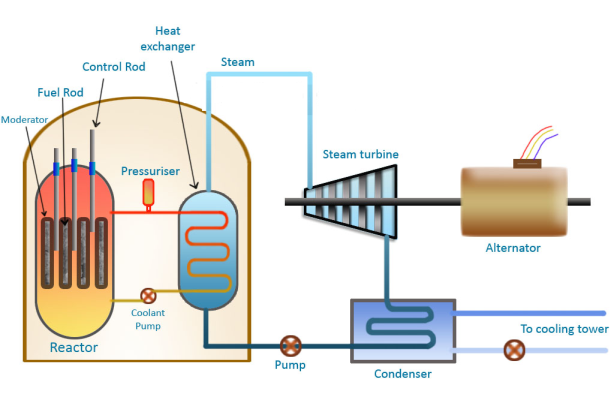
Fig: Working of Nuclear power plant.
Working of nuclear power plant:
- When the uranium atom splits, it releases energy and two or more neutrons from its nucleus. These neutrons can then hit the nuclei of other uranium atoms causing them to fission.
- The sequence of one fission triggering others, and those triggering still more, is called a chain reaction when the atoms split, they release energy in the form of heat.
- The heat is transferred from the reactor core to the water flowing past. That water becomes high pressure steam which turns the turbine in the electric generator.
Advantages:
- Large quantity of energy is released by small amount of fuel.
- No combustion products are required
- It is a clean source of power which does not contribute to air pollution.
Disadvantages:
- Its capital cost is high.
- Require trained man power.
- It has a problem of radioactive waste.
- High degree of safety is needed for person working on this plant against the nuclear radiation.
- Cost of power generation is high.
Introduction:
- The potential energy of water is utilized to move the turbines which is turn run the electric generators. It is cleanest methods of producing electric power.
Component of hydroelectric power plant:
- Dam:
- The dam is the most important component of hydroelectric power plant. The dam is built on a large river that has abundant quantity of water throughout the year.
- It should be built at a location where the height of the river is sufficient to get the maximum possible potential energy from water.
- Water Reservoir:
- The water reservoir is the place behind the dam where water is stored. The water in the reservoir is located higher than the rest of the dam structure.
- The height of water in the reservoir decides how much potential energy the water possesses. The higher the height of water, the more its potential energy. The high position of water in the reservoir also enables it to move downwards effortlessly.
- Intake or Control Gates:
- These are the gates built on the inside of the dam. The water from reservoir is released and controlled through these gates. These are called inlet gates because water enters the power generation unit through these gates.
- When the control gates are opened the water flows due to gravity through the penstock and towards the turbines. The water flowing through the gates possesses potential as well as kinetic energy.
- Water Turbines:
- Water flowing from the penstock is allowed to enter the power generation unit, which houses the turbine and the generator.
- When water falls on the blades of the turbine the kinetic and potential energy of water is converted into the rotational motion of the blades of the turbine. The rotating blades cause the shaft of the turbine to also rotate.
- The turbine shaft is enclosed inside the generator. In most hydroelectric power plants there is more than one power generation unit. There are various types of water turbines such as Kaplan turbine, Francis turbine, Pelton wheels etc.
- Generators:
- It is in the generator where the electricity is produced. The shaft of the water turbine rotates in the generator, which produces alternating current in the coils of the generator.
- It is the rotation of the shaft inside the generator that produces magnetic field which is converted into electricity.
Working of Hydroelectric power plant:
|
Fig:Working of hydroelectric power plant.
- The dam stores lots of water behind it in the reservoir. Near the bottom of the dam wall there is the water intake. Gravity causes it to fall through the penstock inside the dam.
- At the end of the penstock there is a turbine propeller, which is turned by the moving water. The shaft from the turbine goes up into the generator, which produces the power.
- Power lines are connected to the generator that carries electricity to your home and mine. The water continues past the propeller through the tailrace into the river past the dam.

Advantages:
- Operation cost is less.
- More reliable.
- Starting and stopping of these plants takes short time compared with Steam Power Plant.
- It has no ash disposal problem and nuclear waste disposal problem.
- Required less supervising staff.
- These plants can be used for irrigation and flood control purposes in addition to power generation.
Disadvantages:
- The total power developed depends upon the availability of water and hence these are dependent on rainfall.
- These plants are usually away from the place needing electric power, hence cost of transmission lines increases.
- Time required for development of such plant is high.
Overall Efficiency of Hydro Electric power plant
 (Watt)
where,  Density (kg/m3)
 Discharge or Volume flow rate (m3/Sec)
 Available head of water in Meters

Introduction:
- Wind can be used as a power source. Wind power is the use of air flow through wind turbines to mechanically power generators for electricity.
- Wind power, as an alternative to burning fossil fuels, is plentiful, renewable, widely distributed, clean, produces no greenhouse gas emissions during operation, consumes no water, and uses little land.
- The net effects on the environment are far less problematic than those of nonrenewable power sources.
- The wind power can be generated where the wind velocities are more than 8 kmph.
- Such winds are available along the sea coast and at high altitudes in hilly region.
- The wind power is clean and non-polluting
- It has low maintenance cost and low power generation cost of about Rs. 2.25/kWh.
- It needs high capital cost of about 3.5crores/MW.
Construction andWorking of wind power plant:
- It consists of rotor blade, Gear box, generator, power cables, tower and transformer. The blade is attached or connected to the nacelle.
- The gear box is present inside the assembly and generator is connected to it. Through the generator cables are connected and supplied to directly the power supply system.
|
|
|

- Wind (moving air that contains kinetic energy) blows toward the turbine's rotor blades. The rotors spin around, capturing some of the kinetic energy from the wind, and turning the central drive shaft that supports them.
- Although the outer edges of the rotor blades move very fast, the central axle (drive shaft) they're connected toturbine turns quite slowly.
- The gearbox converts the low-speed rotation of the drive shaft into high-speed rotation fast enough to drive the generator. The generator, immediately behind the gearbox, takes kinetic energy from the drive shaft and convert it into electrical energy.
Advantages:
- Non-polluting.
- No fuel is required.
- The cost of generation is low.
Dis-advantages:
- More noisy.
- Weight of system is high.
- Does not provide constant output due to velocity fluctuations.
Overall Efficiency of Hydro Electric power plant


where,  Density of air (kg/m3)
A = Area of wind Turbine (m2)
D = Diameter of wind Turbine (m)
V = Wind Velocity (m/sec)

Introduction
- Solar energy is energy that is in sunlight. It has been used for thousands of years in many different ways by people all over the world.
- As well as its traditional human uses in heating, cooking, and drying, it is used today to make electricity where other power supplies are absent, such as in remote places and in space.
- It is becoming cheaper to make electricity from solar energy and in many situations it is now competitive with energy from coal or oil.
- The sun is producing solar energy through nuclear fusion. In this reaction, two atoms, deutorium (heavy hydrogen) combines to form one atom of helium and during the process if releases large amount of energy which reaches the earth's surface through electromagnetic radiation.
- The sun sends out the energy in the form of radiations at the rate of 3.7 x 10²⁰ MW. However, the energy reached to the earth is about 1.85 x 10¹¹ MW. This energy available is several times more than all the energy produced and consumed in the world today.
Advantages of Solar Energy
- It can be directly converted into electrical energy using photo-voltaic cells.
- Available in abundance.
- Renewable and inexhaustible source of energy.
- Free from pollution.
- It has low operating and maintenance cost.
- No fossil fuels are needed.
- No arrangements are needed for transportation handling and storage of fuels as needed in conventional power plants.
Limitations of Use of Solar Energy
- This energy is dilute and spread out.
- The average power obtainable is only 1 kW/m2 of area in hottest regions. Therefore, large collection area is required.
- The intensity of radiation is weather dependent.
- It is intermittent source of energy since it is not available at night.
- Seasonal variations affects the intensity of radiation.
- The requirement of energy storage devices are heavy in order to cater the energy during the hours of non-availability of solar energy.
Solar collectors
- It is a device for collecting or absorbing the solar radiations on a surface called absorber. Then, Transfer of radiant energy to fluid like water or air in contact with collector takes place. The surface of the collector is designed for high absorption and low emissions.
- Types of Solar Collectors
- Flat plate collectors
- Concentrating type of collectors
- Flat plate collectors
|
- These collectors are used for low temperature applications in the range from room temperature upto 100°C.
- If the working fluid absorbing the heat is liquid, then such collectors are also called as liquid flat plate collectors.
- Flat plate collectors are used for low temperature applications like solar water heating, space heating and cooling, drying, low temperature power generation etc.
2. Concentrating type of collectors
- The cross-section Concentrating type of collector is shown in Fig.
- These collectors are also called as focusing collectors. These are used for medium to high temperature applications.
- These collectors are of two types: (a) Cylindrical parabolic collectors (b) Parabolloid mirror arrays
- (a) Cylindrical parabolic collectors: These types of solar collectors are suitable for application in the range of 100°C to 300°C. These collectors are used for vapour engines and turbines, process heating in industry, refrigeration, cooking etc.
- (b) Parabolloid mirror arrays:
|
These types of solar collectors are used for production of temperatures above 300°C. These are suitable for thermo-electric power generation.
Power generation from solar energy
- Solar Thermal Power Plants
- Solar PV Cell Power Plants
- Construction and working of SOLAR THERMAL POWER PLANT
- It consists of array of concentrating solar collectors, steam generator or Heat Exchanger, steam turbine, condenser and generator as shown in figure. The generator attached to the steam turbine.
|
Fig: Construction and working of solar thermal power plant.
- Concentrating solar collectors are used to produce high pressuresteam which is then used in the conventional steam power plants.
- Solar collectors capture and concentrate sunlight to heat liquid inside the collector, which then heats water in the heat exchanger to create steam. The steam is piped to an onsite turbine-generator to produce electricity.
1.6.2 Construction and working of SOLAR PV-CELL POWER PLANT
|
Solar Photovoltaic (PV) Cell Power Plant
- Solar PV cells generate electricity by absorbing sunlight and using that light energy to create an electrical current. These solar cells are connected in series/parallel array to produce large power output.
- Photovoltaic cells, through the photovoltaic effect, absorb sunlight and generate flowing electricity.
- Step 1: Light is absorbed by the PV cell and knocks electrons loose. First, light strikes a photovoltaic cell and is absorbed by the semiconducting material which is made from (usually silicon). This incoming light energy causes electrons in the silicon to be knocked loose.
- Step 2: Electrons begin to flow, creating an electrical current. There are two layers of silicon used in photovoltaic cells, and each one is specially treated, or “doped”, to create an electric field, meaning one side has a net positive charge and one has a net negative charge. This electric field causes loose electrons to flow in one direction through the solar cell, generating an electrical current.
- Step 3: The electrical current is captured and combined with other solar cells. Once an electrical current is generated by loose electrons, metal plates on the sides of each solar cell collect those electrons and transfer them to wires. At this point, electrons can flow as electricity through the wiring to a solar inverter and then throughout your home.
- Thus DC Electricity is produced. It is supplied to battery through charge controller. DC power can be converted in AC by using an inverter to take up AC loads.
- Function of Charge Controller: During non-sunshine hours, the current can flow from battery to charge controller but it does not allow the current to flow back to PV cells. Therefore it avoids the damage to PV cells.
- Geothermal energy in the form of thermal energy is a form of renewable source of energy having high energy density. It is renewable since the earth's interior will continue to provide energy continuously in the process of cooling of earth's interior.
- It is inexhaustible like solar or wind energy. The geothermal energy in the form of heat energy can be utilized economically and efficiently for power generation and other applications with the existing available technologies.
- Geothermal energy or earth's heat manifests itself on the earth's surface in the following forms:
- Hot water springs.
- The geysers (hot water and steam) and fumaroles (hot steam and hot gases) released periodically in the volcanic region or geothermal fields.
- Volcanic eruptions of geothermal energy in the large quantities released in the form of hot lava, rocks, boiling mud etc.
- Generally the thermal energy available inside the earth is at a depth of more than 80 km. However, there are few locations in the world where this energy can be extracted at a depth of 0.3 km to 3 km called geothermal fields.
Advantages of Geothermal Energy
- It is reliable source of energy which is available continuously throughout the year.
- It is independent of weather conditions.
- No thermal storage facility is required.
- Capital and generation cost is low as compared to conventional thermal power plants.
- No solid pollutants.
- Needs very small land area.
Disadvantages of Geothermal Energy
- It is a low grade heat energy since the temperatures are limited to 150° C.
- Parts of plant may corrode due to presence of salt.
- Geothermal fluids also bring in dissolved gases like H2S, CO2,NH3 gases and other solute which causes air pollution and land pollution if effluent is not discharged into ground.
- Life of plant is low compared to conventional power plants due to corrosive and abrasive geothermal fluids.
- Continuous extraction of fluid may cause settlement of land.
- Causes noise pollution due to exhausts, centrifugal separators, blow down etc. Thus, silencers are needed on some of installed Equipments.
Applications of Geothermal Energy
- Space heating and cooling
- Generation of electrical power
- Industrial process heat, desalination of water, heavy water production, extraction of minerals from geothermal fluids, timber seasoning etc.
1.7.1 Binary Cycle Power Plant (Geo-thermal Power Plant)
- The geothermal resources are available in the temperature range of 90° C to 170° C. This temperature is not sufficient for production of two phase mixture of steam.
- The system of Binary Cycle Power Plant is shown in Figure.
- In order to utilize this geothermal heat, fluid of low boiling temperature like isobutane is used under pressure in a primary heat exchanger.
|
- Geothermalfluid extracted from earth crust is sent to primary heat exchanger where it transfers the heat to isobutane. Thus Vapour of isobutane are generated and is passed through a turbine where it is expanded. The mechanical power of turbine is utilized to produce the electricity by a generator.
- Exhaust vapour of the turbine is passed through aregenerator (heat exchanger) where it gives the heat to the condensate coming from condenser. This Cooled exhaust is then
condensed in the condenser. The returned condensate is heated in the regenerator by exhaust vapour of the turbine. - The geothermal fluid is re-injected after extracting heat in to the ground.
- Hydrogen is the simplest element. An atom of hydrogen consists of only one proton and one electron. It’s also the most plentiful element in the universe. Hydrogen as an alternative fuel since hydrogen is available in abundance in water.
- It reduces the environmental pollution caused by the use of conventional fuels.
- Despite its simplicity and abundance, hydrogen doesn’t occur naturally as a gas on the Earth-it’s always combined with other elements.
- Also, hydrogen provides a large amount of energy on combustion compared to petrol and diesel. It mixes very easily with air and it can burn 4 % lean mixture to 75 % rich mixtures on volume basis.
- H2 can be produced by electrolysis but this method is very expensive.
- H2 is also available as by product from chemical industries like caustic soda and its cost of production is quite comparable with petrol.
- Practical problem in using it, as fuel is due to its high explosive nature on combustion and development of high flame speeds in engines.
- H2 is used as fuel for power generation in fuel cells.
1.8.1 Hydrogen-Oxygen (H2-O2) Fuel Cell
- A fuel cell is an electro-chemical device in which the chemical energy of fuel is continuously converted into electric energy. This conversion of energy takes place at constant pressure and temperature.
- The main components of a fuel cell are:
- A fuel electrode (anode)
- An oxidant electrode (cathode)
- An electrolyte (solution of H2SO4 for acidic fuel cell, KOH for alkali fuel cells)
- container, separators, sealing, fuel and oxidant supply etc.
- The basic feature of a fuel cell is that the fuel and the oxidant are combined in the form of ions than in form of neutral molecules.
- Figure showsthe schematic diagram of a fuel cell using hydrogen as fuel and oxygen as oxidant and alkaline solution of KOH as electrolyte.
- It is called alkaline fuel cell (AFC). It consists of two permeable Nickel electrodes immersed in an electrolyte of good conductivity.
- The porous fuel electrode is anode (negative pole) and the other porous oxidant electrode is cathode (positive pole) are separated by a porous gas barrier. The anode is supplied H2gas as fuel at a certain pressure and the cathode is supplied O2 as oxidant at a pressure.
|
- These gases pass through the respective electrodes and bubble around through the electrolyte solution. Thus gases, electrodes and electrolyte come in contact for their electrochemical reactions. The electrodes are connected through an external circuit.
- The electro-chemical reactions are generally slow and a catalyst is required in the electrodes to accelerate the reaction.
- The hydrogen gas is ionized at anode and it produces a free electron and H+ ions. The reaction at anode is as follows:

- The oxygen supplied to cathode (positive electrode) reacts with water of electrolyte and the electrons transmittedto it to produce hydroxyl (OH) ions. Thus,

- These hydroxyl ions migrate from cathode to anode through electrolyte. The hydrogen and hydroxyl ions then combine in the electrolyte to produce water i.e.

- By adding the above three equations, the overall process is chemical reaction of H2 and O2 gases toform water i.e.

- Thus the net reaction of a fuel cell in which hydrogen and oxygen supplied is the produce water, electrical energy and heat.
Advantages of Fuel Cell
- Conversion efficiencies are very high.
- Require little attention and less maintenance.
- Fuel cell does not make any noise.
- Can be installed near the use point, thus reducing electrical transmission requirements and accompanying losses.
- A little time is needed to go into operation.
- Space requirement considerably less in comparison to conventional power plants.
Disadvantages of Fuel Cell
- High initial cost.
- Low service life.
Definition of Biomass
- Biomass is an organic matter produced by plants both grown on land and grown on water their derivatives and animal manure. The energy obtained from biomass is called biomass energy.
- Coal, petroleum oil and natural gas do not come in the category of 'biomass', because they are produced from dead, buried biomass under pressure and temperature during millions of year. Biomass can also be considered a form of solar energy as the latter is used indirectly to grow these plants by photosynthesis.
Classification of Biomass Resources
- Concentrated wastes
(i) Municipal solid (ii) Sewage wood products (iii) Industrial waste (iv) Manure at large lots.
- Dispersed waste residue: (i) Crop residue (ii) Logging residue (iii) Disposed manure.
- Harvested biomass : (i) Standing biomass (ii) Biomass energy plantations.
1.9.1 Biomass Energy Conversion Process
Direct combustion:
- Combustion is the process of burning in presence of oxygen to produce heat, light and byproducts. Complete combustion to ashes is called incineration.
- Various designs of boilers and furnaces are available to burn biomass like wood, dung, dried vegetable wastes from food industry, pulp, bagasse from sugar industry and municipal wastes etc.
- The moisture content in biomass and their wide range of composition tends to produce low calorific value of fuel.
- However, if biomass energy by combustion is used as co-generation with conventional fuels, the utilization of biomass energy makes it an attractive proposition.
Thermo Chemical Conversion
- These processes can be carried out in following ways.
- Gasification:
- Heating of biomass in presence of limited oxygen and air (deficient O2/air) is called gasification. It produces gaseous fuels like H2, CO, CH4, N2 of low calorific value.
- Pyrolysis:
- It is the heating of biomass in a closed vessel at temperatures in the range of 500°C — 900°C in absence of O2/air or with steam.
- It produces solid, liquids and gases.The pyrolysis process can use all type of organic materials including plastic and rubbers.The gases produced by this process include the mixture of CO, CH4, N2, H2, CO2 and other hydrocarbons.
- The liquids produced are oil like materials (acetic acid, methanol, oil and tar) and solids produced are similar to pure carbon charcoal.
Biochemical Conversion
- The process of biochemical conversion of biomass makes use of metabolic action of microbial organism on biomass to produce liquid and gaseous fuels. These processes are of two types: Fermentation of Biomass and Anaerobic Digestion of Biomass
- Fermentation:
- It is a process of decomposition of complex molecules of organic compound under the influence of micro-organism (ferment) such as yeast, bacteria. enzymes etc.
- The example of fermentation process is the conversion of grains and sugar crops into ethanol and CO, in presence of yeast. 10% of ethanol so produced can be blended with petrol to produce gasohol.
- Anaerobic Digestion of Biomass:
- This process involves the conversion of decaying wet biomass and animal wastes into biogas through decomposition process by the action of anaerobic bacteria.
- The anaerobic bacteria is a micro-organism that can live and grow in absence of O2 or air. For example the production of biogas from human and animal wastes, the decomposition of biomass like sewage sludge, green plants etc.
- The gas produced is mixture of methane (55% to 70%) and remainder is CO, with other impurities.
- The most useful biomass for production of biogas are animal and human waste, algae, hyacinth, plant residue and other organic waste materials with high moisture content.
- The periodic rise and fall of the water level of sea which are carried by the action of the sun and moon on water on, earth is called the 'tide'.
- The main feature of the tidal cycle is the difference in water surface elevations at the high tide and at the low tide. If this differential head could be utilized in operating a hydraulic turbine, the tidal energy could be converted into electrical energy by means of an attached generator.
|
- Figure shows a general arrangement of single basin tidal power plant (double cycle system). Such plants generally use reversible water turbines so that power is generated on low tide as well high tide. The operation of the plant is as follows.
- When the incoming tide sea level and tidal-basin level are equal, the turbine conduit is closed. When the sea level rises, and about half way to high tide the turbine valves are opened and the sea water flows into the basin through the turbine runner generating power.
- This also raises the level of water in the basin. The turbine continues to generate power until the tide passes through its high point and begins to drop.
- When sea and basin water level are again equal, the valves are closed as well as the turbine conduit. The basin level then stays constant while the tide continues to go out. After sufficient head has developed, the turbine valves are again opened and water now from basin to the sea, thereby generating power.
Advantages
- Inexhaustible source
- Low space is needed.
- Pollution free.
Disadvantages
- Due to variation in tide output is not uniform.
- Plant efficiency is variable.
- Higher cost.
- Difficult to install in sea.
- Pump is an apparatus or machine used for raising, driving, exhausting, or compressing fluids or gases by means of a piston, plunger, or set of rotating vanes.
- Pumps are in general classified as Reciprocating pumps or Positive Displacement Pumps and Centrifugal Pumps.
- Centrifugal Pump:
- A centrifugal pump is a device or equipment which converts kinetic energy to pressure energy by a rotating impeller.
- Centrifugal pump works on the principle that when a certain mass of liquid is made to rotate along the impellerabout the central axis of rotation, a centrifugal head is
imparted to liquid. It causes the liquid to move radiallyoutwards at higher velocity.This velocity head is converted in to pressure head in casing. - The simplest explanation is then can be written as a device which generates an increase in pressure of the fluid by transferring mechanical energy of motor to the fluid by the action of rotating impeller.
- The fluid flows from the inlet to the suction eye or the impeller centre and out along the vanes. The kinetic energy from the rotating impeller is transferred to the water in the form of its pressure energy thus increases pressure Head.
|
Constructionof Centrifugal Pump:
- Impeller: An impeller is a wheel or rotor having a series of backward curved vanes or blades. The impeller ismounted on a shaft which is usually coupledto a motor. The motor provides the required input energy to rotate the impeller.
- Casing: The impeller is enclosed in a watertight casing with delivery pipe on one side and with an arrangement onsuction side called eye of impeller. Casing has to perform two functions: (a) it guides the water from entry to exit of impeller, (b) the casing is so designed that it helps in partly converting the kinetic energy of the liquid into pressure energy.
- Suction pipe:The pipe which connects the sump to the eye of impeller is called as Suction pipe. The sump carries the liquid to be lifted by the pump.
- Strainer and foot valve: The suction pipe at its inlet is provided with a strainer and a fool valve.The function of strainer is to prevent the entry of any debris into the pump. The foot valve is a non-return valve which allows the flow of water only in upward direction.
- Delivery pipe: The pipe which connects the outlet of pump to delivery point is called delivery pipe. A valve is provided in the delivery pipe near the outlet of the pump called delivery valve. Its function is to regulate the supply of liquid from the pump to delivery Pipe.
Working of Centrifugal Pump:
- The steps involved in operation of centrifugal pump are as follows
- The delivery valve is closed. The priming of the pump is carried out. Priming involves the filling the liquid in suction pipe and casing upto the level of delivery valve so that no air pockets are left in the system.
- The pump shaft and impeller is now rotated with the help of prime mover, like electric motor. The rotation of impeller inside a casing full of liquid produces a forced vortex which is responsible in imparting the centrifugal head to the liquid.
- It creates a vacuum at the eye of impeller and causes liquid to rise into suction pipe from the sump.
- Now the delivery valve is opened and the liquid is lifted and discharged through the delivery pipe due to its high pressure. Thus the liquid is continuously sucked from the sump to impeller eye and it is delivered from the casing of pump through the delivery pipe.
- A machine that extracts air from the atmosphere and compresses it into a holding chamber.
- Air Compressor- is used to compress the atmospheric air to high pressure.
- The three basic types of air compressors are
- Reciprocating
- Rotary screw
- Rotary centrifugal
- Reciprocating Compressor:
- Reciprocating air compressors are positive displacement machines, meaning that they increase the pressure of the air by reducing its volume.
- This means they are taking in successive volumes of air which is confined within a closed space and elevating this air to a higher pressure.
- The reciprocating air compressor accomplishes this by a piston within a cylinder as the compressing and displacing element.
- The reciprocating air compressor is single acting when the compressing is accomplished using only one side of the piston. A compressor using both sides of the piston is considered double acting.
- Construction
- The reciprocating type compressor consists of a piston which is enclosed within the cylinder & equipped with suction & discharge valves.
- The piston receives power from main shaft through crankshaft and connecting rod. A flywheel/belt wheel is fitted on the crankshaft which is driven by electric motor or diesel engine. It supplies uniform motion throughout the cycle of operations.
1.12.1.2 Working:
- The compression of air is done by first drawing a volume of air into its cylinder through suction valves during suction stroke by the piston & then compressing & discharging it on the return stroke of the piston through delivery valves.
- This simple working is used in every Reciprocating Air Compressor.
|
Fig: Suction and Delivery Stroke of a Reciprocating Air Compressor
- In single stage reciprocating air compressor the entire compression is carried out in a single cylinder. If the compression is affected in one end of the piston & cylinder then it is known as single acting & if the compression is affected in both ends of piston & cylinder then it is known as double acting reciprocating air compressor.
1.12.1.3 Application of Compressed Air:
- Inflating tyres /tubes
- In spray Paintings
- For cleaning purposes in garages along with water for washing cars etc.
- Gas turbines
- Diesel Engines, Air Brakes
1.13.1 Introduction
- A turbine is a turbo machine with at least one moving part called a rotor assembly, which is a shaft or drum with blades attached. Moving fluid acts on the blades so that they move and impart rotational energy to the rotor.
1.13.2 Impulse Turbine
|
Fig: Impulse Turbine working principle
- The steam jets are directed at the turbine's bucket shaped rotor blades where the pressure exerted by the jets causes the rotor to rotate and the velocity of the steam to reduce as it imparts its kinetic energy to the blades.
- The blades in turn change the direction of flow of the steam however its pressure remains constant as it passes through the rotor blades since the cross section of the chamber between the blades is constant.
- Impulse turbines are therefore also known as constant pressure turbines. The next series of fixed blades reverses the direction of the steam before it passes to the second row of moving blades.
- If a jet of steam is discharged from a fixed nozzle at a high speed over a flat stationary plate, a steady force will be exerted over this plate. This force is nothing but an impulse.
- No work is done as the plate is fixed. But, if a number of such plates are fixed on the rim of a wheel, the wheel may be rotated due to the impulse of steam. Curved plates are used instead of flat plates to utilize greater amount of energy.
- In the impulse turbine, steam is expanded in the fixed nozzle only. In the nozzle the velocity of steam increases with decrease of pressure. As the steam passes over the blades, the pressure remains constant with a decrease of velocity.
1.13.3 Reaction Turbine:
- A reaction turbine is a type of turbine that develops torque by reacting to the pressure or weight of a fluid; the operation of reaction turbines is described by Newton's third law of motion (action and reaction are equal and opposite).
|
Fig: Reaction Turbine working principle
- The rotor blades of the reaction turbine are shaped more like aerofoils, arranged such that the cross section of the chambers formed between the fixed blades diminishes from the inlet side towards the exhaust side of the blades.
- The chambers between the rotor blades essentially form nozzles so that as the steam progresses through the chambers its velocity increases while at the same time its pressure decreases, just as in the nozzles formed by the fixed blades.
- Thus the pressure decreases in both the fixed and moving blades. As the steam emerges in a jet from between the rotor blades, it creates a reactive force on the blades which in turn creates the turning moment on the turbine rotor, just as in steam engine. (Newton's Third Law - For every action there is an equal and opposite reaction).
- In a reaction turbine, the blades sit in a much larger volume of fluid and turn around as the fluid flows past them. A reaction turbine doesn't change the direction of the fluid flow as drastically as an impulse turbine: it simply spins as the fluid pushes through and past its blades. Wind turbines are perhaps the most familiar examples of reaction turbines.
1.13.4 Difference between impulse and reaction turbine
Impulse Turbine | Reaction Turbine |
In this turbine all the pressure energy is converted into KE. | Some amount of pressure energy is converted into KE. |
Steam is expanded completely in nozzle. | Steam is partially expanded in nozzle. |
Less efficiency | High efficiency |
Suitable for small power requirement. | Suitable for medium and large power requirement. |
Occupy less space | Occupy more space |
High rotor speed. | Low rotor speed. |
1.14.1 Working
- Impulse turbine works on the basic principle of impulse. When the jet of water strikes at the turbine blade with full of its speed, it generates a large force which used to rotate the turbine.
- The force is depends on the time interval and velocity of jet strikes the blades.
- This turbine used to rotate the generator, which produces electric power. High pressure water flow form dam (high head) to nozzle (low head).
|
- This water flows through divergent nozzle where it’s all pressure energy change into kinetic energy. It forms a water jet.
- The water jet strikes the blade at high speed which rotates the rotor.It transfers all kinetic energy of water to the rotor, which further use to rotate the generator.
- After transferring energy, water flows to the tail race.This process run continuously until sufficient power generates.
Reference Books
1. Khan, B. H., “Non Conventional Energy Sources, Tata McGraw-Hill Publisher Co. Ltd.
2. Boyle, Godfrey, “Renewable Energy”,2nd Ed., Oxford University Press
3. Khurmi, R.S. ,and Gupta, J. K.,“A Textbook of Thermal Engineering”, S. Chand & Sons
4. Incropera, F. P. and Dewitt, D.P., (2007), “Fundamentals of Heat and Mass Transfer, 6th Ed., John Wiley and Sons, USA
5. Groover,Mikell P., (1996), “Fundamentals of Modern Manufacturing: Materials, Processes, and Systems”, Prentice Hall, USA
6. Norton, Robert L., (2009), “Kinematics and Dynamics of Machinery”, Tata McGrawHill
7. Cleghorn, W. L., (2005), “Mechanisms of Machines”, Oxford University Press
8. Juvinal, R. C., (1994), “Fundamentals of Machine Component Design”, John Wiley and Sons, USA
9. Ganeshan, V., (2018), “Internal Combustion Engines”, McGraw Hill
10. Anderson, Curtis Darrel and Anderson,Judy, (2010), “Electric and Hybrid Cars: A History”, 2nd Ed., McFarland


