Unit 4
Vehicle Systems
- Chassis (frame)
- Axles
- Wheels
- Suspension System
- Steering System
- Engine (E)
- Clutch (C)
- Gear Box (GB)
- Propeller Shalt and Universal Joints
- Differential Gear Box (D)
- Radiator
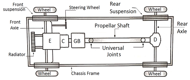
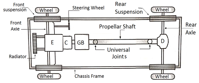
- Chassis (Frame):
- Askeleton frame of a vehicle on which various components of vehicle are mounted. (Radiator, engine, gearbox, suspension system, steering system, fuel tank, etc)
2. Axles:
- It is the part on which chassis is mounted. The axles are supported between the wheels.
- Front axle: it supports the chassis on front side. The steering mechanism is mounted on front axle.
- Rear axle: it supports the chassis on rear side. The rear axle consists of driving shaft enclosed in tubular structure.
3. Wheels:
- Wheels are used to support the axles, the load of vehicle and passengers is supported by wheels through axles.
4. Suspension System:
- Chassis is mounted on the axles through the suspension system. The suspension system isolates (he vehicle body and passengers from road shocks.
5. Steering System:
- Steering mechanism is used for turning the wheels or vehicles in desired direction. It is mounted on front axle.
6. Engine:
- Engine is an internal combustion engine (I.C. Engine) which converts chemical energy of fuel into mechanical power at the crankshaft.
7. Clutch:
- Clutch is mounted between the engine and the gear box.
- It is used to engage or disengage the engine from gear box as per the will of the driver.
- When clutch is engaged, power is transmitted from engine to gear’ box. When clutch is disengaged by pressing clutch pedal, there is no power transmission from engine to gear box.
8. Gear Box:
- Gear box receives the power from engine through clutch and transmits the power to the propeller shaft.
- In gear box, torque is increased and speed 1 reduced. Gear box produces different speed ranges for the vehicle.
9. Propeller Shaft and Universal Joints:
- Propeller shaft is a mechanical element that transmits the power from gear box to the differential on rear axle.
- At one end, propeller shaft is connected to the gear box through universal joint and at other end, it is connected to the differential through universal joint.
10. Differential Gear Box:
- Differential gear box transmits the power from the propeller shaft to the shaft of the rear axle. The shaft of rear axle is at right angles to the propeller shaft.
- The shaft of the rear axle transmits the power to the wheels.The differential gear box transmits the power at right angles.
- In addition, differential allows the two wheels to rotate at different speeds when vehicle is taking the turn.
11. Radiator:
- Radiator is a heat exchanger placed at the front of the vehicle. It cools the hot coolant coming from the engine and sends it back to the engine.
TYPES OF AUTOMOBILE LAYOUT
Based on position of engine and drive axle the autombile layouts are having following types.
- Front Engine Rear Wheel Drive
- Rear Engine Rear Wheel Drive
- Front Engine Front Wheel Drive
- Four Wheel Drive
- Front Engine Rear Wheel Drive:
- The engine is mounted in the front part of vehicle and the drive is transmitted to the rear axle
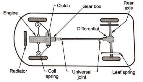
Figure: Front Engine Rear Wheel Drive
- The drive chain in this layout is :
Engine —> Clutch —> gearbox —> universal joint—> propeller shaft --> differential —› rear axle —> wheels
Advantages:
- Balanced weight distribution in a vehicle (front axle carries the engine weight and rear axle carries the passenger weight).
- Simple front axle design with steering mechanism.
- Increased luggage carrying capacity at rear.
- Linkages controlling the engine are short and simple such as clutch, accelerator linkages, etc.
- Accessibility to various engine components is easier.
- Better engine cooling by taking full benefits of natural air stream flowing across the radiator.
Disadvantages :
- It requires long propeller shaft to transmit the drive from gearbox to differential.
- The rear floor houses the propeller shaft and hence rear leg space is limited.
- Higher noise transmitted from front engine to driver cabin.
- It requires larger brake pads at front wheels because of higher weight being transferred on front wheels while deceleration.
2. Rear Engine Rear Wheel Drive:
- This type of layout eliminates the necessity of a propeller shaft.
- The engine is mounted at the rear and drive is also transmitted to the rear axle.
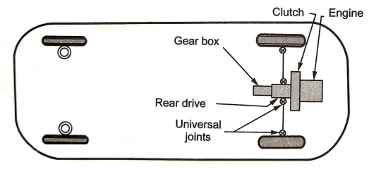
Figure: Rear Engine Rear Wheel Drive
- The drive chain for this layout is:
Engine --> clutch --> gearbox --> universal joints differential --> rear axle
Advantages :
- The front axle consists of a very simple design houses the steering mechanism only.
- Because of high w axle, eight on the driving provides excellent traction and grip on steep hills
- More space avaialable for body design.
- Less Noise in Driver cabin.
Disadvantages :
- Radiator is needed as natural air cooling is not possible.
- Because of higher weight concentration at rear, the vehicle has a tendency to oversteer while taking a sharp turn.
- Luggage space at front is restricted due to small compartment that houses the fuel tank and spare wheel.
3. Front Engine Front Wheel Drive:
- This layout is the most compact layout.
- It is being popularly used on most hatchback cars in India.
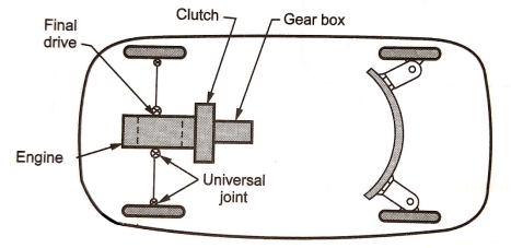
Figure: Front Engine Front Wheel Drive
- The drive chain for this layout is :
Engine --> clutch --> gearbox --> universal joints --> differential --> rear axle --> Wheels
Advantages:
- Compact design of vehicle.
- Due to higher weight of the steering wheels, it provides stable steering during turns.
- Reduced skidding on slippery roads.
- No propeller shaft is required.
- It has a flat rear floor due to absence of propeller shaft.
- Better engine cooling takes place due to natural air stream flowing across the engine radiator.
Disadvantages:
- The front wheel design is complicated because it supports the engine, differential and steering mechanism.
- High noise transmission from engine compartment to driver cabin.
4. Four Wheel Drive:
- Sometimes while driving on rural or uneven or rough unconstructed roads, automobile With conventional layout (2 - wheel drive) gets stuck the pothole.
- It becomes difficult for driver to get the automobile out of the pothole or ditch.
- The case is more severe if the drive wheel itself gets stuck in such a pothole or ditch.
- Hence to provide better maneuverability i.e. drive and traction on all the four wheels of the vehicle, four wheel drive train is used.
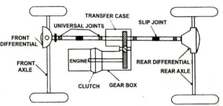
Figure: Four Wheel Drive
Advantages:
- Better traction.
- Excelelnt road handling charateristics.
- Vehicle can move on rough or uneven roads.
Disadvantages:
- More weight.
- High cost.
- Design is complex.
- Suspension system is mounted between the automobile chassis and the axles (front axle and rear axle) to isolate the vehicle body from road shocks.
- Suspension system consists of spring or spring and damper. The damper, which is known as shock absorber, consists of piston cylinder arrangement filled with oil.
Functions of Suspension System
- It prevents the vehicle body and frame from road shocks.
- It gives stability of the vehicle.
- It safeguards the passengers and goods from road shocks.
- It gives the good road holding while driving, cornering and braking.
- It gives cushioning effect.
- It provides comfort.
Requirements of Suspension System
- There should be minimum deflection.
- It should be of low initial cost.
- It should be of minimum weight.
- It should have low maintenance and low operating cost.
- It should have minimum tyre wear.
Types of Suspension System
- Leaf Spring Suspension System
- Telescopic Suspension System (Coil Spring & damper)
- Telescopic Suspension System (without Coil Spring)
- Leaf Spring
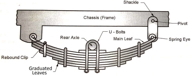
Figure: Leaf Spring
- Semi-elliptic leaf springs are almost universally used for suspension in light and heavy commercial vehicles. For cars also, these are widely used for rear suspension, but now replaced completely by coil springs.
- Figure shows a rear axle leaf spring of semi-elliptic type. The spring consists of a number of leaves called blades.
- The blades vary in length as shown. The composite spring is based upon the theory of a beam of uniform strength. The lengthiest blade has eyes on its ends. This blade is called master leaf.
- All the blades are bound together by means of steel straps as shown. The spring is supported on the axle, front or rear by means of a U-bolt.
- One end of the spring is mounted on the frame with a simple pin, while on the other end, connection is made with a shackle.
- When the vehicle comes across a projection on the road surface, the wheel moves up, deflecting the spring.
- This changes the length between the spring eyes. If both the ends are fixed, the spring will not be able to accommodate this change of length. This is provided for by means of a shackle at one end which gives flexible connection.
2. Telescopic Suspension System (Coil spring & damper)
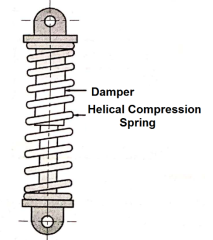
Components and working of telescopic suspension system (coil spring and damper):
- Helical compression spring (colt spring)
- Damper (shock absorber)
- Helical compression spring (coil spring):
The helical compression spring absorbs the energy of road shocks. Due to this spring tends to oscillate.
- Damper (shock absorber):
The damper consistsof piston cylinder arrangement filled with the oil.The oil in damper restrictstheoscillationofhelical compression spring (coil spring).
- Application of telescopic suspension system(coil spring and damper):
The load carrying capacity of coil springand damper isless than the leaf spring. It is used in two wheelers and lightmotor vehicles (cars).
3. Telescopic Suspension System (Without Coil spring)
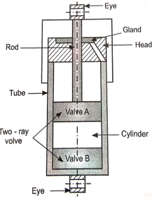
Construction:
- The telescopic shock absorber consists of a cylinder to which a head is welded to screwed to the outer tube.
- The space between outer and inner tube is called reservoir. A pressed steel cap and axle eye by means of which cylinder is screwed to the axle are welded to the outer tube.
- A piston slides inside the cylinder and screwed to the piston rod at which its upper end of chassis eye, it is attached to the frame of the vehicle.
- The part of the piston rod that is outside of the cylinder is protected by a cover which is welded to the chassis eye.
- A piston rod gland packing prevent the leakage, when the piston passes through the head and any fluid is trapped by it is supplied to the reservoir through drain hole.
Working:
- If the axle eye moves upwards then the fluid must be displaced from the bottom. Top side of the bottom side fluid through the outer ring of the piston by lifting the non-return valve.
- But since Increase in the volume of upper end of the cylinder is less than the volume of the lower end. Fluid will also displaced through the inner ring of holes of non-return valve of foot valve, and the level at the fluid will raise in the reservoir.
- The pressure setup will depend on the size of hole in the piston and Foot valve and the squire of the speed of which the cylinder is moved. For downward motion of the cylinder the fluid will be displaced form the upper end of the piston.
- In the leaver end through the inner ring of hole of non-return valve in the piston.
- The fluid will also be draw in the lower end of the cylinder from the reservoir to the outer ring of hole of non-return valve of the foot valve.
Advantages
- It provides softer suspension.
- It reduces wheel wobbling
- It reduces the tendency of fitting of the wheel on one side due to road vibration
- It provides more space for engine accommodation.
- The movement of the spring on one wheel is not transmitted to the other wheel.
Disadvantages
- High initial cost.
- High maintenance.
- More rigid frame or chassis is needed.
- Steering system is a mechanism used for converting the rotary motion of steering wheel into angular motion of front wheels to turn the vehicle in desired direction.
- The most commonly used steering system is Ackermann Steering System.
Requirements of Steering System
- It must keep the wheel at all times in to rolling motion without rubbing on the road.
- It must light and stable.
- It should also absorb the road shocks.
- It must easily be operated with less maintenance.
- It should have self-centering action to some extent.
Functions of Steering System
- It helps in swinging the wheels to the left or right.
- It helps in turning the vehicle at the will of the driver.
- It provides directional stability.
- It is used to minimize the tyre wear and tear.
- It helps in achieving self-centering efforts.
- It absorbs major part of the road shocks.
Ackermann Steering System.
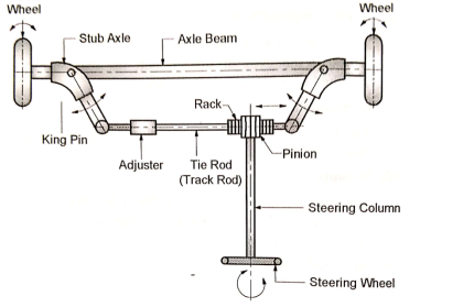
Figure: Ackermann Steering System.
- Axle Beam:
- Vehicle chassis is supported on axle beam through the suspension system.
- Axle beam takes the weight of vehicle and transmits it to stub axle.
2. Stub Axle:
- Stub axles are pivoted at the two ends of the axle beam by king pins.
- One end of stub axle carries the wheel and brake drum while other end is connected to the tie rod.
3. King Pin (Swivel Pin) :
- Kin pin pivots the stub axle on axle beam.
4. Tie Rod :
- Two stub axles are connected to each other by tie rod. Adjuster helps to adjust the length of tie rod.
- Tie rod is important part of steering mechanism.
5. Rack and Pinion:
- In order to achieve the turn of the wheels, the stub axles need to be oscillated about the king pin. The oscillatory motion of stub axles can be achieved bygiving the linear motion to the tie rod.
- Rack mounted on the tie rod engages with pinionmounted on steering column.
6. Steering Column :
- When steering column rotates, the pinion mounted on steering column also rotates.
- The rotary motion of pinion is converted into linear motion of rack and tie rod.
7. Steering Wheel :
- Driver rotates steering wheel so as to rotate the steering column.
- The rotary motion of steering wheel is converted into angular motion of front wheels.
Types of Steering System
- Rack and Pinion Type Steering System
- Worm and Worm Wheel Type Steering System
- Recirculating Ball Screw Type Steering System
- Power Steering System
- Braking system is an arrangement of various linkages and components used to slow down or completely stop the moving vehicle within the shortest possible time by applying artificial frictional resistance.
- In a process of performing the function, the brake absorbs the kinetic energy of moving vehicle and converts it to heat energy.
- The heat generated by brake is unwanted energy and has to be dissipated to surrounding air. In hybrid vehicles, this energy absorbed by brake is converted into electric energy, which is further stored in battery.
Functions of Brakes
- It is used to stop the vehicle.
- It is used to control the speed where and when required.
- It is used to control the vehicle while descending along the slope.
- To park the vehicle and held it in stationary position without the presence of Driver.
Requirements of Automobile Brakes
- It should work efficiently irrespective of road condition and quality.
- The retardation must be uniform throughout its application.
- The pedal effort must be within the convenient capacity of the driver.
- It should be in minimum weight.
- It should have long life.
- It should be easy to maintain and adjust.
- Noise and vibrations are to be minimum.
Classification of Brakes:
- By Method of Power
a) Mechanical brakes
b) Hydraulic brakes
c) Vacuum brakes
d) Air brakes
e) Electrical brakes
f) Magnetic brakes
g) Air assisted hydraulic brake
- By Method of Application
a) Service or foot brakes
b) Parking or hand brakes
- By Method of Operation
a) Manual
b) Servo
- By method of Braking contact
a) Internal Expanding Brakes
b) External Contracting Brakes
- By Method of Applying Brake Force
a) Single Acting Brakes
b) Double Acting Brakes
Types of Mechanical Brakes
a) Drum Brakes
b) Disc Brakes
Hydraulib Braking System
- A figure below shows the schematic layout of hydraulic braking system. Various components and their working is as follows.
1. Brake Pedal and Brake Lever :To apply brake. Driver presses the brake pedal.
2. Master Cylinder:
- The brake pedal is connected to the piston of the master linder through brake lever and other mechanical linkages.
- As the piston of the master cylinder moves forward, the braking force is converted into pressure energy of brake.
3. Fluid Lines :
- The fluid lines carry the high pressure brake fluid from master cylinder to the four wheel cylinders.
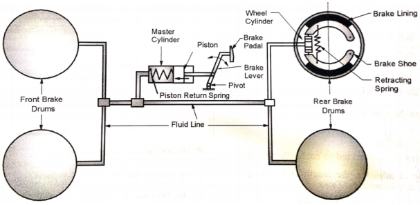
Figure: Hydraulib Braking System
4. Wheel Cylinder :
- In wheel cylinders, the high pressure brake fluid applies the force on the pistons of the wheel cylinders.
5.Brakes:
- The pistons of the wheel cylinder provide the actuating force for : (1) brake shoes in case of drum brakes ; or (ii) calipers in case of disk brakes.
- When brake is released, the piston return spring of the master cylinder pushes the piston in backward direction and fluid pressure inside the fluid line drops.
Internal Expanding Shoe Brake (Drum Brake):
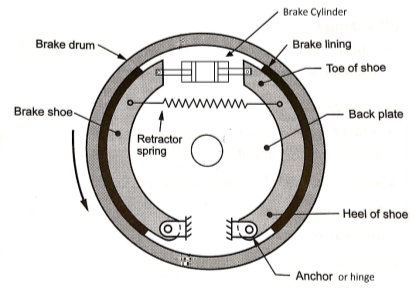
Figure: Intenal Expanding shoe brake
- The drum brake (internal expanding shoe brake), shown in Fig. consists of two shoes. The outer surface of the shoes are lined with some friction material.
- Each shoe is pivoted at one end about the hinge-pin and subjected to an actuating force at the other end. The actuating force on both the shoes is applied by a wheel (hydraulic) cylinder or a cam mechanism.
- When the actuating force is applied, the shoes are pressed against the rotating brake drum, thus causing the brake drum either to retard or stop completely.
- When the actuating force is released, the retracting spring return the brake shoes, so that they no longer contact the drum.
Application of drum brake :
- The drum brakes (internal expanding shoe brakes) are used in automobile vehicles (trucks, buses, cars, motorcycles, scooters, etc.).
Disc Brake
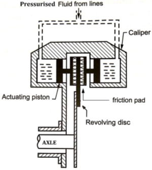
Figure: Disc Brake
- As shown in Figure, a disc brake consists of a cast iron disc bolted to the wheel hub and a stationary housing called caliper.
- The caliper is connected to some stationary part of the vehicle, like the axle casing or the stub axle and is cast in two parts, each part containing a piston.
- In between each piston and the disc, there is a friction pad held in position by retaining pins, spring plates etc.
- Passages are drilled in the caliper for the fluid to enter or leave each housing. These passages are also connected to another one for bleeding. Each cylinder contains a rubber sealing ring between the cylinder and the piston.
- When the brakes are applied, hydraulically actuated pistons move the friction pads into contact with the disc, applying equal and opposite forces on the later.
- On releasing the brakes, the rubber sealing rings act as return springs and retract the pistons and the friction pads away from the disc.
- We know that in case of Internal Combustion engines, combustion of air and fuel takes place inside the engine cylinder and hot gases are generated.
- The temperature of gases will be around 2300-2500°C. This is a very high temperature and may result into burning of oil film between the moving parts and may result into seizing or welding of the same.
- So, this temperature must be reduced to about 150-200°C at which the engine will work most efficiently.
- Too much cooling is also not desirable since it reduces the thermal efficiency. So, the object of cooling system is to keep the engine running at its most efficient operating temperature.
- It is to be noted that the engine is quite inefficient when it is cold and hence the cooling system is designed in such a way that it prevents cooling when the engine is warming up and till it attains to maximum efficient operating temperature, then it starts cooling.
- It is also to be noted that :
(a) About 20-25% of total heat generated is used for producing brake power (useful work).
(b) Cooling system is designed to remove 30-35% of total heat.
(c) Remaining heat is lost in friction and carried away by exhaust gases.
- There are mainly two types of cooling systems :
(a) Air cooling system
(b) Water cooling system
Air cooling system
- Air cooled system is generally used in small engines say up to 15-20 kW and in aero plane engines.
- In this system fins or extended surfaces are provided on the cylinder walls, cylinder head, etc.
- Heat generated due to combustion in the engine cylinder will be conducted to the fins and when the air flows over the fins, heat will be dissipated to air.
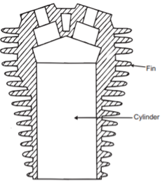
Figure: Air Cooling System
- The amount of heat dissipated to atmosphere depends upon :
(a) Amount of air flowing through the fins.
(b) Fin surface area.
(c) Thermal conductivity of metal used for fins.
Water Cooling System
- In water-cooling system, the water or coolant is used as a medium of cooling.
- The cylinder of I.C. Engine is surrounded by Water jacket.
- The water or coolant flows through the water jacket and absorbs the heat from cylinder.
- The hot water from engine jacket flows through theradiator. The radiator consists of header tank, collector tank and tubes with fins.
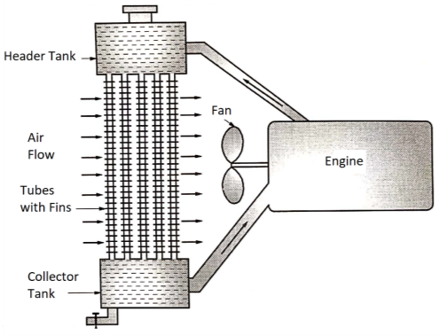
Figure: Water Cooling System
- The hot water or coolant flows through the radiator tubes where it loses its heat to air.
- The cold water or coolant is again supplied to engine jacket.
- The fan induces the air to flow over the radiator tubes, which helps to cool the coolant flowing through the radiator tubes.
- Application of water-cooling system: Water cooling system is highly effective. Hence, it is used in four wheelers.
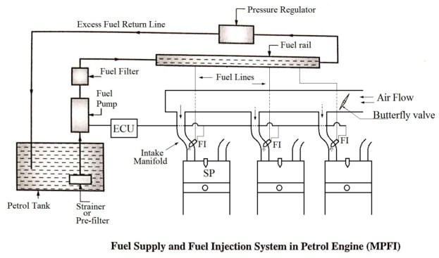
- Traditionally carburetor is an essential element of fuel supply system in petrol engine.
- It is now being replaced in petrol four-wheelers by multi-point fuel injection (MPFI) system.
- Various parts in the MPFI System are explained below.
1. Petrol Tank:
- Petrol is stored in petrol tank.
2.Fuel Pump:
- Fuel pump increases the pressure of the petrol before feeding it to the fuel rail. The fuel pump is driven by engine camshaft or electric motor.
3.Fuel Filter:
- The high pressure petrol passes through the fuel filter, where it is filtered so as to remove the dust and dirt particles.
4. Fuel Rail:
- The high pressure petrol is then supplied to the fuel rail.
5. Fuel Injector:
- A fuel injector is placed in intake manifold of each cylinder. The high pressure petrol enters the fuel injector and fuel injector injects the petrol into intake manifold at high velocity.
- The air is flowing though the intake manifold. The homogenous air and petrol mixture then enters the engine cylinder through the inlet valve.
6. Pressure Regulator:
- The pressure regulator controls the pressure of petrol in fuel rail.
7. Electronic Control Unit (ECU) :
- The ECU controls the fuel injection system. ECU decides the amount of fuel injected and timing of fuel injection in each cylinder.
FUEL SUPPLY AND FUEL INJECTION SYSTEM IN DIESEL ENGINE
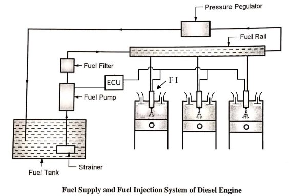
1. Diesel Tank:
- Diesel is stored in petrol tank.
2. Fuel Pump:
- The fuel pump increases the pressure of diesel before feeding it to the fuel rail. The fuel pump is driven by engine camshaft or electric motor.
3. Fuel Filter:
- The high pressure diesel passes through the fuel filter where it is filtered so as to remove the dirt particles.
4. Fuel Rail:
- The high pressure diesel is then supplied to the fuel rail.
5. Fuel Injector:
- The fuel injector is placed in a cylinder head of each cylinder. The high pressure diesel enters the fuel injector and the fuel injector injects the diesel into cylinder at the end of compression stroke.
6. Pressure Regulator:
- The pressure regulator controls the pressure of diesel in fuel rail.
7. Electronic Control Unit (ECU):
- The ECU controls the fuel injection system. It decides the amount of fuel injected and timing of fuel injection.
- The mechanism that transmits the power developed by the engine of automobile to the engine to the driving wheels is called the transmission system (or power train).
- It is composed of Clutch, gear box, Propeller shaft, Universal joints, differential and axle.
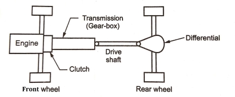
Figure: Transmission System
Functions or need of Transmission System
- Provide means of connection and disconnection of engine with rest of power train without shock and smoothly.
- Provide a varied leverage between the engine and the drive wheels
- Provide means to transfer power in opposite direction.
- Enable power transmission at varied angles and varied lengths.
- Enable speed reduction between engine and the drive wheels.
- Enable diversion of power flow at right angles.
- Provide means to drive the driving wheels at different speeds when required.
- Bear the effect of torque reaction, driving thrust and braking effort effectively.
- A clutch is a mechanism which enables the rotary motion of one shaft to be transmitted to second shaft, whose axis is coincident with that of first.
- The clutch is located between the engine and gear box when the clutch is engaged, the power flows from the engine to the rear wheels through the transmission system and the vehicle moves.
- When the clutch is disengaged, the power is not transmitted to the rear wheels and the vehicle stops while the engine is still running.
- The clutch is disengaged when
- Starting the engine
- Shifting the gears
- Stopping the vehicle
- Idling the engine
- The clutch is engaged only when the vehicle is to move and is kept engaged when the vehicle is moving.
Types of Friction Clutches
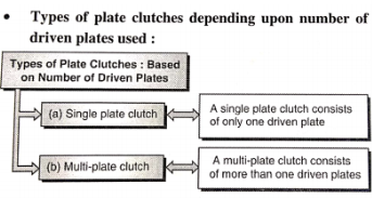
- Plate or Disk Clutches
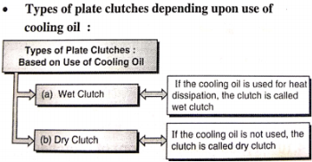
- Single plate clutch (Dry clutch&Wet clutch)
- Multiplate clutch(Dry clutch & Wet clutch)
- Cone Clutches
- Centrifugal Clutches
Plate or Disk Clutches:
- The plate clutch consists of a set of driving plates and driven plates arranged alternately.Plate clutches are popular in automobiles.
|
Cone Clutches:
- The cone clutch consists of cup keyed to the driving shaft and a cone with friction lining free to slide axially on the splined drive shaft.
Centrifugal Clutch:It works on the principal of centrifugal force.
Function of a Clutch
- To permit engagement or disengagement of a gear when the vehicle is stationary and the engine is running.
- To transmit the engine power to the road wheels smoothly without shock to the transmission system while setting the wheel in motion.
- To permit the engaging of gears when the vehicle is in motion without damaging the gear wheels.
Requirements of a Clutch
- It should be engage gradually to avoid sudden jerks.
- It should be easily operated (i.e it should consume minimum physical effort at the time of engagement and disengagement)
- It should be dynamically balanced (particularly required in case of high speed engine clutches)
- It should be free from slip when engaged.
- It should be as possible so that it will occupy minimum space.
- It should be easily accessible and have simple means of adjustment.
- It should be suitable mechanism to damp vibrations and to eliminated noise produced during the power transmission.
- It should be able to dissipate large amount of heat which is generated during the clutch operation due to friction.
SINGLE PLATE CLUTCH
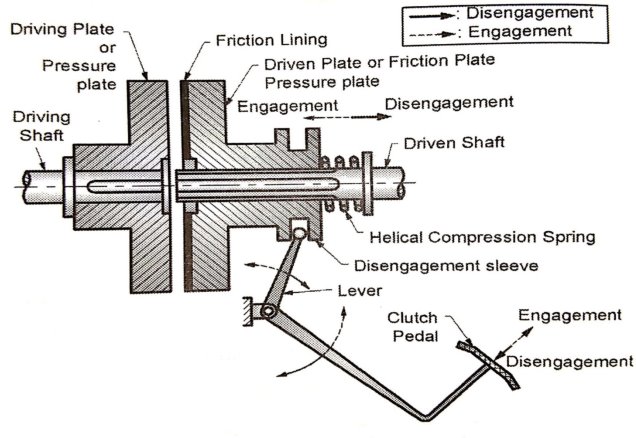
- Components of Single Plate Clutch are
- One or Two Driving (Pressure) Plates
- One Driven (Friction) Plate
- Helical Compression Springs
- Disengagement Mechanism
- Driving (pressure) plate :
The driving plate is rigidly keyed to the driving shaft, while the driven plate is free to slide axially on the splined driven shaft. The driving plate is also known as pressure plate.
- Driven (friction) plate :
The friction lining, made of friction materials like asbestos, is either riveted or pasted to the driven plate. Thedriven plate is also known as friction plate or clutch plate.
- Helical compression springs :
- The helical compression spring exerts the axial force on the driven plate or friction plate or clutch plate.
- Disengagement mechanism :
The disengagement mechanism, which consists of disengagement sleeve, lever and clutch pedal, is used for disengaging the clutch.
OR
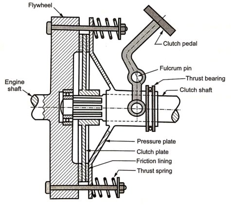
Figure: Single Plate Clutch
Working of Single Plate Clutch:
- The helical compression spring presses the driven plate (friction plate) against the driving plate (pressure plate). The spring creates an axial force between the driven plate (friction plate) and the driving plate (pressure plate).
- Frictional force between the two plates is responsible for transmitting the torque or power.
- Engaged condition:The torque is transmitted from driving shalt through key to the driving plate (pressure plate), from driving plate to the driven plate (friction plate) due to frictional force, and finally from driven plate through the splines to the driven shaft.
- Due to force exerted by the helical compression spring, the clutch is normally in engaged condition.
- In order to disengage the clutch, the clutch pedal is pressed downward, as shown in Fig. Due to this, the lever displaces the disengagement sleeve to the right.
- Disengaged condition:The spring force is neutralized by the external force applied on the disengagement sleeve. Hence, there is no axial pressure between the driving plate (pressure plate) and driven plate (friction plate); and there is no frictional force between the two contacting surfaces.
- Therefore, even though the driving shaft and driving plate are rotating, the driven plate and driven shaft are stationary; and there is no transmission of torque or power from the driving shaft to the driven shaft.
- The single plate clutches are used where large radial space is available such as : trucks, buses, cars, etc.
- Gear box receives the power from engine through clutch and transmits the power to the propeller shaft
- In gear box torque is increased and speed is reduced. Great box produces different speed ranges for the vehicle.
Need of Geer Box in Vehicles:
- In automobile vehicle the I.C. Engine operates at high speed but the torque produced by I.C. Engine is not very high.
- If I.C. Engine is directly connected to the wheels, the engine torque may not be enough to drive the vehicle.
- The gear box receives the power form engine at high speed. It reduces the speed and increases the torque, which is adequate to drive the vehicle.
- I.C. Engines operate over limited speed range. However, automobile vehicle has to run over the wide range of speeds and torque. The gear box provides wide range of speeds and torque to the vehicle.
Functions of Gear Box:
- Gear box reduces the speed and increases the torque.
- Gear box provides wide range of speeds and torque to the vehicle.
- With reverse gear, gear box provides the means to move the vehicle in reverse direction.
- In neutral position, the gear box disconnects the I.C. Engine from the wheel even with the clutch in the engaged position.
Types of Gear Box
- Sliding Mesh type gear box
- Constant Mesh type gear box
- Synchro Mesh type gear box
CONSTANT MESH GEAR BOX
- Components of Constant Mesh Gear Box are:
- Input Shaft (Clutch Shaft)
- Output Shaft (Main Shaft)
- Lay Shaft (Counter Shaft)
- Gears (A1, A2, B1, B2, C1, C2, D1, D2)
- Dog Clutches (S1, S2)
- Gear Shifting Mechanism
- Input Shaft (Clutch Shaft) :
- The input shaft of gear box is connected to the engine through clutch. It receives the power at high speed and low torque) from the engine.
- Output Shaft (Main Shaft):
- The output shaft of the gear box is connected to the propeller shaft through the universal joint. It transmits power (at low speed and high torque) to the propeller shaft. It is a splined shaft.
- The gears B1, C1 and D1 are free to rotate on this shaft. The dog clutches S1 and S2 can slide axially on this shaft.
- Lay Shaft (Counter shaft) :
- The lay shaft is a shaft parallel to input and output shafts. The gears A2, B2, C2 and D2 are rigidly mounted on it.
- Gears :
- Gear A1 is mounted on input shaft and it is constantly in engagement with gear A2 mounted on the lay shaft.
- Gears A2, B2, C2 and D2 are rigidly mounted on the lay shaft.
- Gears B1, C1 and D1 are free to rotate on splined output shaft.
- Dog Clutches :
- The dog clutches S1 and S2 are free to slide axially on splined shaft. The dog clutch S1 can engage with gear A1 orgear B1.
- Similarly the dog clutch S2 can engage with gear C1 or gear D1.
- Gear Shifting Mechanism :
- Thegear shifting mechanism is operated by gear lever to shift or change the gears.
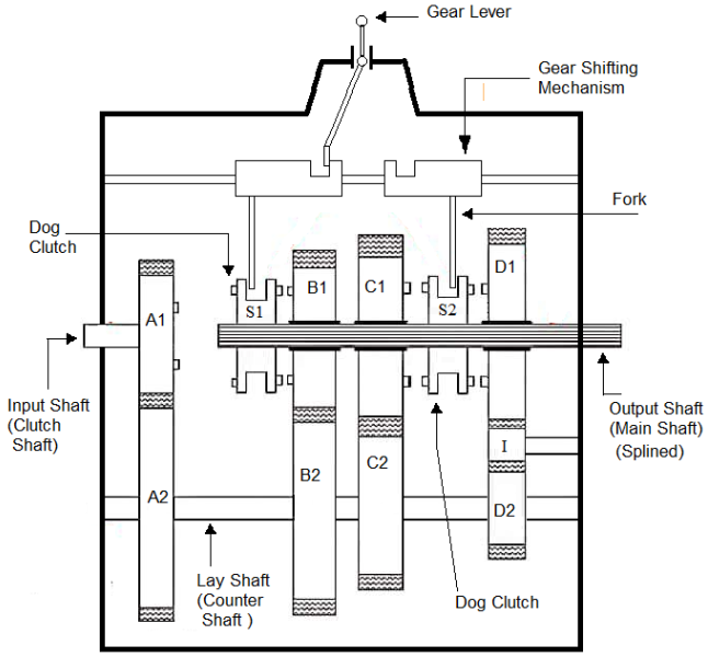
Figure: Constant Mesh Gear Box
Working of Constant mesh Gear Box
- In this type of gearbox, all the gears of the main shaft are in constant mesh with corresponding gears of the countershaft.
- The gears on the main shaft which are bushed are free to rotate. The dog clutches are provided on main shaft. The gears on the lay shaft are, however, fixed.
- When the left Dog clutch is slid to the left by means of the selector mechanism, its teeth are engaged with those on the clutch gear and we get the direct gear.
- The same dog clutch, however, when slid to right makes contact with the second gear and second gear is obtained.
- Similarly movement of the right dog clutch to the left results in low gear and towards right in reverse gear.Usually the helical gears are used inconstant mesh gearbox for smooth and noiseless operation.
- 1st gear :
- To engage 1stgear, dog clutch S2 is shifted to left to engage with gear C1.
- Power flow: Input Shaft - Gear A1- Gear A2- Lay Shaft - Gear C2 - Gear C1 — Dog Clutch S1- Output Shaft.
- 2nd Gear:
- To engage 2ndgear, dog clutch S2 is shifted to right to disengage from gear C1 and dog clutch S1 is shifted to right to engage with gear B1.
- Power flow: Input Shaft - Gear A1- Gear A2- Lay Shaft - Gear B1 - Gear B2- Dog Clutch S1 - Output Shaft.
- 3rd gear :
- To engage 3rd gear, dog clutch S1 is shifted to left to engage with gear A1.
- Power flow: Input Shaft - Gear A1 — Dog Clutch S1- Output Shaft.
- Reverse Gear :
- To engage reverse gear, dog clutch S1 is shifted to right to disengaged from gear A1 and dog clutch S2 is shifted to right to engage with gear D1.
Gear ratio (speed ratio) of gear box:
- Gear ratio speed ratio of gear box is the ratio of speed of input shaft (engine shaft) to the speed of output shaft (propeller shaft).
- Let,
- Ni = speed of input shaft of gear box (r.p.m.)
- No = speed of output shaft of gear box (r.p.m.)
- I = gear ratio or speed ratio

- The gear ratio (speed ratio) of gear box is different in different gears. It is maximum in 1st gear and minimum in last gear.
Power Transmission Capacity of Gear Box:
- Let,
- Pi= input power to gear box (engine power), Watt
- Po = output power of gear box (propeller shaft power), Watt
- Ti = input torque to gear box (enginetorque), N-m
- To output torque of gear box, (propeller shaft torque), N-m
- Input power


- Output power


- Efficiency of Gear Box

- If Efficiency of Gear Box is 100 %, i.e.
 , then


- Propeller shaft is connecting the drive from gear box to final drive. Hence it is also called Drive Shaft.
- It is the group of parts connecting the transmission with the drive wheels.
- It consists of propeller shaft (also called Drive Shaft), Universal Joints/Constant Velocity Joints and Slip Joints.
- Shaft: As this must withstand torsional loads, it is usually made of tubular cross-section. It also has to be well balanced to avoid whirling at high speeds. Shafts are made of steel, aluminum or composite materials.
- The rotational motion of the gear box main shaft is transferred to the differential unit for rotating the drive wheels.
- Universal Joint: One or two universal joints, depending upon the type of rear axle drive used. The universal joints account for the up and down movements of the rear axle when the vehicle is running.
- Universal joint is provided to transmit the power at changing angles of the propeller shaft, while vehicle isrunning.
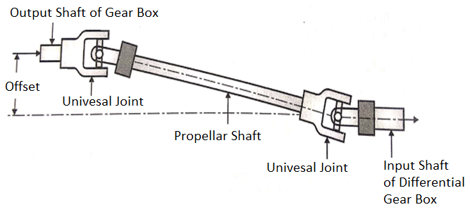
Figure: Propeller Shaft
- A universal joint allows driving torque to be carried through two shafts that are at an angle with each other.
- A simple universal joint consist two Y- shaped yoke, one on the driving shaft and other on the driven shaft. The four arms of spider are assembled in needle bearings in the two yokes.
- The driving shaft and yoke force the spider to rotate. The other two trunnions of the spider then cause the driven yoke to rotate.
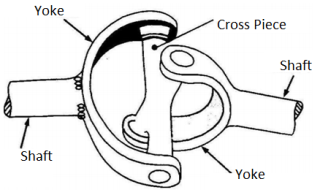
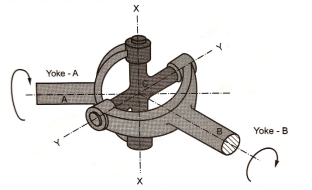
Figure: Universal Joint
- When the two shafts are at an angle with each other, the needle bearings permit the yokes to swing around on the trunnions with each revolution.
- A simple universal joint does not transmit the motion uniformly when the shafts are operating an angle. Because of this, two universal joints are used in a vehicle, one between the gear box and the propeller shaft and other between the propeller shaft and the differential pinion shaft.
DIFFERENTIAL GEAR BOX
Differential gear box transmits the power from the propeller shaft to the shaft of rear axle.
Functions of Differential Gear Box
1. The shaft of rear axle is at right angles to the propeller shaft. The differential gear box transmits the power at right angles.
2. The differential gear box allows the two wheels to rotate at different speeds when vehicle is taking the turn.
3. The differential gear box increases the torque and reduces the speed from propeller shaft to rear axle shaft.
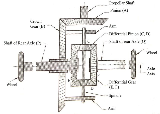
Differential Gear Box
Working of Differential Gear Box
- When the automobile runs on a straight path, the differential gears E and F and differential pinions C and D acts as one unit and rotates with the crown gear B. Hence, the differential gears E and F rotate with the same speed and in the same direction as that of crown 0-gear B. There is no relative motion between C, D, E and F. The differential pinion C and D do not rotate about their own axes.
- When automobile is taking right turn, the inner rear wheel (i.e. gear F which is keyed to the rear axle Q) should have lesser speed than the outer rear wheel (i.e. gear E which is keyed to the rear axle P). Due to relative speed of the inner and outer differential gears F and E, the pinion C and D start rotating about the spindle axis and at the same time revolve about the rear axle axis also. Due to this epicycle effect, the speed of the inner rear wheel (gear F) is decreases by a certain amount and the speed of outer rear wheel (gear E) increases by the same amount.
It is the axle where the motion from the propeller shaft is transferred. In case of four wheel drive, the motion is transferred to both the axles and therefore both the axles are 'live' axles. When motion is transferred to one axle the other axle is termed as 'dead' axle. The dead axle only carries the weight of the vehicle.
The live axle performs the following two functions:
- It acts as a beam and through the suspension springs carries the load due to the weight of the carriage unit. It transmits these loads under dynamic conditions through the road wheels to the ground.
- It also supports and accommodates the final drive, differential and shafts.
Front Axle:
- Front axle is used for steering the front wheels carried on the stub axle. It is the major component of a vehicle designed to transmit the vehicle weight to the front steering wheels through the front suspension system. Fig. Shows a conventional front axle.
- The front axle has to take vertical vehicle load, bending loads due to weight, and torque loads due to braking and acceleration.
- To withstand the above loads, the axle is made of section in the central portion while the ends are made elliptical.
Rear Axle:
- Rear axle drives are employed on front engine rear wheel drive vehicles.
- The rear axle drive system consists of important sub-systems such as universal joints, slip joint, propeller shaft, suspension leaf springs, rear axle, rear axle casing, final drive and differential.
- The rear axle drive system is subjected to the following forces and torques.
Need of Safety:
- Vehicles are driven for long distances, at high speeds, with heavy loads and other adverse conditions.
- It is hence important to ensure safety of passengers inside the vehicle, pedestrians on the road and the luggage carried by the vehicle.
- Vehicle safety is the study and practice of design, construction, equipment and regulation to minimize the occurrence and consequences of automobile.
Active Safety System:
- Active safety systems are those that improve driving safety through technology designed to prevent accidents before they happen.These are technology systems assisting in the prevention of an accident.
- They are also referred as primary safety system. Active safety systems use an understanding of the state of the vehicle to both avoid and minimize the effects of a crash.
- The modem vehicle has various electronic sensors and microprocessor controlled actuators that assist driver to have better control on the vehicle.
- These forward-looking technologies are expected to play an increasing role in accident avoidance and mitigation.
- Examples of active safety systems are :
- ABS - Antilock Braking System
- TCS - Traction Control System
- ESP - Electronic Stability Program
- Cruise Control
- Tyre Pressure Monitoring system
- Night Vision System
- Anti-lock Braking System
- Antilock braking systems (ABSs) are electronic systems that monitor and control wheel slip during vehicle braking.
- ABS can improve vehicle control during braking and reduce stopping distances on slippery road surfaces by limiting wheel slip and minimizing lockup. Reducing wheel slip improves vehicle stability and control during braking, since stability increases as wheel slip decreases.
Working Principle of ABS
- This system consists of a central (ECU) Electronic Control Unit and four-wheel speed sensors connected to each wheel and two hydraulic valves. There is a valve in the brake line of each brake controlled by the ABS.
- The valve has three positions:
- 1st- The valve is open; pressure from the master cylinder is passed right through to the brake.
- 2nd- The valve blocks the line, isolating that brake from the master cylinder.
- 3rd - In position three, the valve releases some of the pressure from the brake.
- When the ECU finds that any wheel is turning faster than the other wheel, automatically brake hydraulic pressure to the affected wheel is increased by the ABS system so that braking force is reapplied, and the wheel slows down.
- This complete process performed by the ABS is repeated continuously throughout the drive on mostly uneven roads and can be easily detected by the driver of the car with the help of brake pedal pulsation.
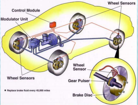
- The wheel speed sensors continuously monitor the speed of each wheel and transmit this information to electronic control unit.
- If wheel is about to lock under heavy braking, the hydraulic control valve reduces the braking pressure of that single wheel until the threat of locking is past.
- Once the wheel turns freely, the braking pressure is again increased. This increase and decrease of braking pressure continues until driver reduces the force applied on brake pedal or until the tendency of lock is overcome.
ABS Components
Hydraulic Components:
1. Accumulator: It is used to store hydraulic fluid to maintain high pressure.
2. Antilock hydraulic control valve assembly: It controls the release and application of the brake system pressure.
3. Booster pump: It is used to provide pressurized hydraulic fluid.
4. Booster/Master Cylinder Assembly: It is needed to modulate hydraulic pressure in the wheel circuit.
5. Fluid Accumulator: It temporarily stores brake fluid that is removed from the wheel brake.
6. Main Valve: This is a two-position valve and is open only in the ABS mode.
7. Modulator Unit: It controls the flow of pressurized brake fluid to the individual wheel circuits.
8. Solenoid Valves: It is in the modulator unit and are electrically operated by signals from the control module.
Electrical / Electronic components:
1. ABS control module: It monitors system operation and controls antilock function when needed.
2. Brake pedal sensor: Its function is to switch on the brake lights to alert other vehicles that the car is slowing down and/or is going to stop.
3. Wheel speed sensor: These are generally used for sensing the wheel speed.
Advantages of ABS
- It allows the driver to maintain directional stability and control over steering during braking.
- Safe and effective.
- Automatically changes the brake fluid pressure at each wheel to maintain optimum brake performance.
- ABS absorb the unwanted turbulence shock waves and modulates the pulses thus permitting the wheel to continue turning.
Disadvantage of ABS
- It is very costly.
- Maintenance cost of a car equipped with ABS is more.
Passive Safety System:
- Passive safety systems are those that protect passengers once an accident has occurred, by reducing risk and severity of injury.
- These are technology systems for reducing impact of crash on passengers.
- They are also referred as secondary safety system.
- These systems are only deployed or effective response to a vehicle accident.
- Examples of passive safety systems are:
- Seatbelt
- Pretensioners
- Airbag - front and side airbags
- Seat Belt:
- A seat belt is a safety harness designed secures the occupant of a vehicle against harmful effects resulting during a collision or a sudden stop.
- The seat belt is sometimes also referred as safety belt.
- A seat belt reduces the likelihood and the injury in a traffic collision by stopping the vehicle occupant from hitting hard against interior elements of the vehicle or other passengers.
- The seat belt keeps the occupant positioned correctly on its seat for maximum benefit from the impact.
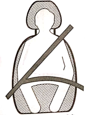
Figure: Seat Belt
Need for seat belt
- Seat Belts (Safety Belts) is a safety system designed to secure the passengers against harmful and dangerous movements arising out of collision or sudden stop of vehicle.
- When passenger and vehicle are travelling at same speed. The seat belt is fairly loose and passenger can make comfortable movements. When the driver applies the brake and stops the vehicle suddenly or when vehicle stops suddenly due to collision, due to inertia, the seat belt applies opposite force on the driver and passengers to prevent them from hitting against interior part of the vehicle or falling out of the vehicle through windshield.
2. Seat
- A car seat is the seat used in automobiles. Most of the car seats are made from inexpensive but durable material to withstand prolonged use.
- The commonly used material for seats is polyester. In latest cars the arrangement of seat is bucket type.
- It is a separate seat with encountered platform designed to accomodate one person distinct from a bench seat i.e. a platform designed to seat upto three people.
- Individual bucket seats typically have rounded backs and may offer a variety of adjustments to fit different passangers.
- Some sedan models offer fold-down rear seats to gain cargo space when they are occupied by passangers.
- According to motor vehicle safety act the seats should be properly anchored and the construction of automobile seats should be proper.
- In addition to this, the act also includes that a child to sit up front is should be 5 feet and they must weight upto 40 kg.
- Side airbags are often built right into the side of the seat.
- Some modern cars like BMW, Audi, Benz etc. are equipped with a battery powered automatic control to adjust how the seat sits into a car.
- Some vehicle let the driver save the adjustments in memory (memory seat) for later recall with the push of a button.
- Car seat covers are accessories that protect the original seat from wear and tear.
- It also add a custom look to a vehicle's interior. This can maintain the resale value of the car and maximize the comfort of the driver and passangers.
3. Air Bags
- The airbag was invented to perform as a safety cushionbetween the passangers and the hard surfaces of the car.
- It is also referred as Supplemental Restraint System (SRS), Air Cushion Restraint System (ACRS) and Supplemental Inflatable Restraint (SIR).
- It consists of a flexible envelope designed to inflate rapidly during an automobile collision.
- Its purpose is to cushion occupants during a crash and provide protection to their bodies when they strike interior objects such as the steering wheel or a window.
- The airbag is designed to only inflate in moderate to severe frontal crashes.
- Airbags are normally designed with the intention of supplementing the protection to an occupant who is correctly restrained with a seatbelt.
- Most designs are inflated through pyrotechnic means and can only be operated once.
- This airbag inflation is controlled by the Airbag Electronic Control Unit (AECU). After deployment, the inflated airbags need to be replaced and the ECU usually needs to be reset.
- Components of Airbag system The major components of airbag system are Crash sensors, Airbag Electronic Control Unit (AECU), Detonator and Inflatable airbag.
References:
1. Khan, B. H., “Non Conventional Energy Sources, Tata McGraw-Hill Publisher Co. Ltd.
2. Boyle, Godfrey, “Renewable Energy”,2nd Ed., Oxford University Press
3. Khurmi, R.S. ,and Gupta, J. K.,“A Textbook of Thermal Engineering”, S. Chand & Sons
4. Incropera, F. P. And Dewitt, D.P., (2007), “Fundamentals of Heat and Mass Transfer, 6th Ed., John Wiley and Sons, USA
5. Groover,Mikell P., (1996), “Fundamentals of Modern Manufacturing: Materials, Processes, and Systems”, Prentice Hall, USA
6. Norton, Robert L., (2009), “Kinematics and Dynamics of Machinery”, Tata McGrawHill
7. Cleghorn, W. L., (2005), “Mechanisms of Machines”, Oxford University Press
8. Juvinal, R. C., (1994), “Fundamentals of Machine Component Design”, John Wiley and Sons, USA
9. Ganeshan, V., (2018), “Internal Combustion Engines”, McGraw Hill
10. Anderson, Curtis Darrel and Anderson,Judy, (2010), “Electric and Hybrid Cars: A History”, 2nd Ed., McFarland
Unit 4
Vehicle Systems
- Chassis (frame)
- Axles
- Wheels
- Suspension System
- Steering System
- Engine (E)
- Clutch (C)
- Gear Box (GB)
- Propeller Shalt and Universal Joints
- Differential Gear Box (D)
- Radiator
- Chassis (Frame):
- Askeleton frame of a vehicle on which various components of vehicle are mounted. (Radiator, engine, gearbox, suspension system, steering system, fuel tank, etc)
2. Axles:
- It is the part on which chassis is mounted. The axles are supported between the wheels.
- Front axle: it supports the chassis on front side. The steering mechanism is mounted on front axle.
- Rear axle: it supports the chassis on rear side. The rear axle consists of driving shaft enclosed in tubular structure.
3. Wheels:
- Wheels are used to support the axles, the load of vehicle and passengers is supported by wheels through axles.
4. Suspension System:
- Chassis is mounted on the axles through the suspension system. The suspension system isolates (he vehicle body and passengers from road shocks.
5. Steering System:
- Steering mechanism is used for turning the wheels or vehicles in desired direction. It is mounted on front axle.
6. Engine:
- Engine is an internal combustion engine (I.C. Engine) which converts chemical energy of fuel into mechanical power at the crankshaft.
7. Clutch:
- Clutch is mounted between the engine and the gear box.
- It is used to engage or disengage the engine from gear box as per the will of the driver.
- When clutch is engaged, power is transmitted from engine to gear’ box. When clutch is disengaged by pressing clutch pedal, there is no power transmission from engine to gear box.
8. Gear Box:
- Gear box receives the power from engine through clutch and transmits the power to the propeller shaft.
- In gear box, torque is increased and speed 1 reduced. Gear box produces different speed ranges for the vehicle.
9. Propeller Shaft and Universal Joints:
- Propeller shaft is a mechanical element that transmits the power from gear box to the differential on rear axle.
- At one end, propeller shaft is connected to the gear box through universal joint and at other end, it is connected to the differential through universal joint.
10. Differential Gear Box:
- Differential gear box transmits the power from the propeller shaft to the shaft of the rear axle. The shaft of rear axle is at right angles to the propeller shaft.
- The shaft of the rear axle transmits the power to the wheels.The differential gear box transmits the power at right angles.
- In addition, differential allows the two wheels to rotate at different speeds when vehicle is taking the turn.
11. Radiator:
- Radiator is a heat exchanger placed at the front of the vehicle. It cools the hot coolant coming from the engine and sends it back to the engine.
TYPES OF AUTOMOBILE LAYOUT
Based on position of engine and drive axle the autombile layouts are having following types.
- Front Engine Rear Wheel Drive
- Rear Engine Rear Wheel Drive
- Front Engine Front Wheel Drive
- Four Wheel Drive
- Front Engine Rear Wheel Drive:
- The engine is mounted in the front part of vehicle and the drive is transmitted to the rear axle
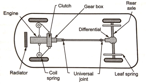
Figure: Front Engine Rear Wheel Drive
- The drive chain in this layout is :
Engine —> Clutch —> gearbox —> universal joint—> propeller shaft --> differential —› rear axle —> wheels
Advantages:
- Balanced weight distribution in a vehicle (front axle carries the engine weight and rear axle carries the passenger weight).
- Simple front axle design with steering mechanism.
- Increased luggage carrying capacity at rear.
- Linkages controlling the engine are short and simple such as clutch, accelerator linkages, etc.
- Accessibility to various engine components is easier.
- Better engine cooling by taking full benefits of natural air stream flowing across the radiator.
Disadvantages :
- It requires long propeller shaft to transmit the drive from gearbox to differential.
- The rear floor houses the propeller shaft and hence rear leg space is limited.
- Higher noise transmitted from front engine to driver cabin.
- It requires larger brake pads at front wheels because of higher weight being transferred on front wheels while deceleration.
2. Rear Engine Rear Wheel Drive:
- This type of layout eliminates the necessity of a propeller shaft.
- The engine is mounted at the rear and drive is also transmitted to the rear axle.
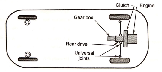
Figure: Rear Engine Rear Wheel Drive
- The drive chain for this layout is:
Engine --> clutch --> gearbox --> universal joints differential --> rear axle
Advantages :
- The front axle consists of a very simple design houses the steering mechanism only.
- Because of high w axle, eight on the driving provides excellent traction and grip on steep hills
- More space avaialable for body design.
- Less Noise in Driver cabin.
Disadvantages :
- Radiator is needed as natural air cooling is not possible.
- Because of higher weight concentration at rear, the vehicle has a tendency to oversteer while taking a sharp turn.
- Luggage space at front is restricted due to small compartment that houses the fuel tank and spare wheel.
3. Front Engine Front Wheel Drive:
- This layout is the most compact layout.
- It is being popularly used on most hatchback cars in India.
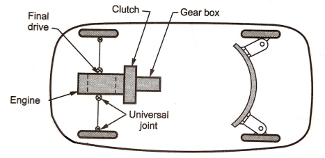
Figure: Front Engine Front Wheel Drive
- The drive chain for this layout is :
Engine --> clutch --> gearbox --> universal joints --> differential --> rear axle --> Wheels
Advantages:
- Compact design of vehicle.
- Due to higher weight of the steering wheels, it provides stable steering during turns.
- Reduced skidding on slippery roads.
- No propeller shaft is required.
- It has a flat rear floor due to absence of propeller shaft.
- Better engine cooling takes place due to natural air stream flowing across the engine radiator.
Disadvantages:
- The front wheel design is complicated because it supports the engine, differential and steering mechanism.
- High noise transmission from engine compartment to driver cabin.
4. Four Wheel Drive:
- Sometimes while driving on rural or uneven or rough unconstructed roads, automobile With conventional layout (2 - wheel drive) gets stuck the pothole.
- It becomes difficult for driver to get the automobile out of the pothole or ditch.
- The case is more severe if the drive wheel itself gets stuck in such a pothole or ditch.
- Hence to provide better maneuverability i.e. drive and traction on all the four wheels of the vehicle, four wheel drive train is used.
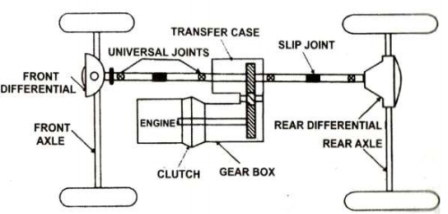
Figure: Four Wheel Drive
Advantages:
- Better traction.
- Excelelnt road handling charateristics.
- Vehicle can move on rough or uneven roads.
Disadvantages:
- More weight.
- High cost.
- Design is complex.
- Suspension system is mounted between the automobile chassis and the axles (front axle and rear axle) to isolate the vehicle body from road shocks.
- Suspension system consists of spring or spring and damper. The damper, which is known as shock absorber, consists of piston cylinder arrangement filled with oil.
Functions of Suspension System
- It prevents the vehicle body and frame from road shocks.
- It gives stability of the vehicle.
- It safeguards the passengers and goods from road shocks.
- It gives the good road holding while driving, cornering and braking.
- It gives cushioning effect.
- It provides comfort.
Requirements of Suspension System
- There should be minimum deflection.
- It should be of low initial cost.
- It should be of minimum weight.
- It should have low maintenance and low operating cost.
- It should have minimum tyre wear.
Types of Suspension System
- Leaf Spring Suspension System
- Telescopic Suspension System (Coil Spring & damper)
- Telescopic Suspension System (without Coil Spring)
- Leaf Spring
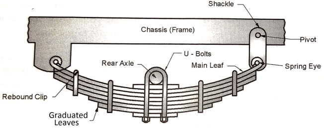
Figure: Leaf Spring
- Semi-elliptic leaf springs are almost universally used for suspension in light and heavy commercial vehicles. For cars also, these are widely used for rear suspension, but now replaced completely by coil springs.
- Figure shows a rear axle leaf spring of semi-elliptic type. The spring consists of a number of leaves called blades.
- The blades vary in length as shown. The composite spring is based upon the theory of a beam of uniform strength. The lengthiest blade has eyes on its ends. This blade is called master leaf.
- All the blades are bound together by means of steel straps as shown. The spring is supported on the axle, front or rear by means of a U-bolt.
- One end of the spring is mounted on the frame with a simple pin, while on the other end, connection is made with a shackle.
- When the vehicle comes across a projection on the road surface, the wheel moves up, deflecting the spring.
- This changes the length between the spring eyes. If both the ends are fixed, the spring will not be able to accommodate this change of length. This is provided for by means of a shackle at one end which gives flexible connection.
2. Telescopic Suspension System (Coil spring & damper)
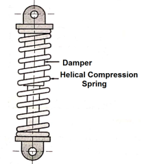
Components and working of telescopic suspension system (coil spring and damper):
- Helical compression spring (colt spring)
- Damper (shock absorber)
- Helical compression spring (coil spring):
The helical compression spring absorbs the energy of road shocks. Due to this spring tends to oscillate.
- Damper (shock absorber):
The damper consistsof piston cylinder arrangement filled with the oil.The oil in damper restrictstheoscillationofhelical compression spring (coil spring).
- Application of telescopic suspension system(coil spring and damper):
The load carrying capacity of coil springand damper isless than the leaf spring. It is used in two wheelers and lightmotor vehicles (cars).
3. Telescopic Suspension System (Without Coil spring)
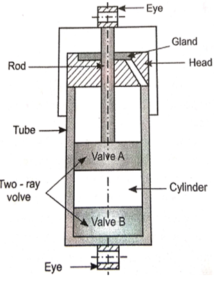
Construction:
- The telescopic shock absorber consists of a cylinder to which a head is welded to screwed to the outer tube.
- The space between outer and inner tube is called reservoir. A pressed steel cap and axle eye by means of which cylinder is screwed to the axle are welded to the outer tube.
- A piston slides inside the cylinder and screwed to the piston rod at which its upper end of chassis eye, it is attached to the frame of the vehicle.
- The part of the piston rod that is outside of the cylinder is protected by a cover which is welded to the chassis eye.
- A piston rod gland packing prevent the leakage, when the piston passes through the head and any fluid is trapped by it is supplied to the reservoir through drain hole.
Working:
- If the axle eye moves upwards then the fluid must be displaced from the bottom. Top side of the bottom side fluid through the outer ring of the piston by lifting the non-return valve.
- But since Increase in the volume of upper end of the cylinder is less than the volume of the lower end. Fluid will also displaced through the inner ring of holes of non-return valve of foot valve, and the level at the fluid will raise in the reservoir.
- The pressure setup will depend on the size of hole in the piston and Foot valve and the squire of the speed of which the cylinder is moved. For downward motion of the cylinder the fluid will be displaced form the upper end of the piston.
- In the leaver end through the inner ring of hole of non-return valve in the piston.
- The fluid will also be draw in the lower end of the cylinder from the reservoir to the outer ring of hole of non-return valve of the foot valve.
Advantages
- It provides softer suspension.
- It reduces wheel wobbling
- It reduces the tendency of fitting of the wheel on one side due to road vibration
- It provides more space for engine accommodation.
- The movement of the spring on one wheel is not transmitted to the other wheel.
Disadvantages
- High initial cost.
- High maintenance.
- More rigid frame or chassis is needed.
- Steering system is a mechanism used for converting the rotary motion of steering wheel into angular motion of front wheels to turn the vehicle in desired direction.
- The most commonly used steering system is Ackermann Steering System.
Requirements of Steering System
- It must keep the wheel at all times in to rolling motion without rubbing on the road.
- It must light and stable.
- It should also absorb the road shocks.
- It must easily be operated with less maintenance.
- It should have self-centering action to some extent.
Functions of Steering System
- It helps in swinging the wheels to the left or right.
- It helps in turning the vehicle at the will of the driver.
- It provides directional stability.
- It is used to minimize the tyre wear and tear.
- It helps in achieving self-centering efforts.
- It absorbs major part of the road shocks.
Ackermann Steering System.
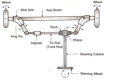
Figure: Ackermann Steering System.
- Axle Beam:
- Vehicle chassis is supported on axle beam through the suspension system.
- Axle beam takes the weight of vehicle and transmits it to stub axle.
2. Stub Axle:
- Stub axles are pivoted at the two ends of the axle beam by king pins.
- One end of stub axle carries the wheel and brake drum while other end is connected to the tie rod.
3. King Pin (Swivel Pin) :
- Kin pin pivots the stub axle on axle beam.
4. Tie Rod :
- Two stub axles are connected to each other by tie rod. Adjuster helps to adjust the length of tie rod.
- Tie rod is important part of steering mechanism.
5. Rack and Pinion:
- In order to achieve the turn of the wheels, the stub axles need to be oscillated about the king pin. The oscillatory motion of stub axles can be achieved bygiving the linear motion to the tie rod.
- Rack mounted on the tie rod engages with pinionmounted on steering column.
6. Steering Column :
- When steering column rotates, the pinion mounted on steering column also rotates.
- The rotary motion of pinion is converted into linear motion of rack and tie rod.
7. Steering Wheel :
- Driver rotates steering wheel so as to rotate the steering column.
- The rotary motion of steering wheel is converted into angular motion of front wheels.
Types of Steering System
- Rack and Pinion Type Steering System
- Worm and Worm Wheel Type Steering System
- Recirculating Ball Screw Type Steering System
- Power Steering System
- Braking system is an arrangement of various linkages and components used to slow down or completely stop the moving vehicle within the shortest possible time by applying artificial frictional resistance.
- In a process of performing the function, the brake absorbs the kinetic energy of moving vehicle and converts it to heat energy.
- The heat generated by brake is unwanted energy and has to be dissipated to surrounding air. In hybrid vehicles, this energy absorbed by brake is converted into electric energy, which is further stored in battery.
Functions of Brakes
- It is used to stop the vehicle.
- It is used to control the speed where and when required.
- It is used to control the vehicle while descending along the slope.
- To park the vehicle and held it in stationary position without the presence of Driver.
Requirements of Automobile Brakes
- It should work efficiently irrespective of road condition and quality.
- The retardation must be uniform throughout its application.
- The pedal effort must be within the convenient capacity of the driver.
- It should be in minimum weight.
- It should have long life.
- It should be easy to maintain and adjust.
- Noise and vibrations are to be minimum.
Classification of Brakes:
- By Method of Power
a) Mechanical brakes
b) Hydraulic brakes
c) Vacuum brakes
d) Air brakes
e) Electrical brakes
f) Magnetic brakes
g) Air assisted hydraulic brake
- By Method of Application
a) Service or foot brakes
b) Parking or hand brakes
- By Method of Operation
a) Manual
b) Servo
- By method of Braking contact
a) Internal Expanding Brakes
b) External Contracting Brakes
- By Method of Applying Brake Force
a) Single Acting Brakes
b) Double Acting Brakes
Types of Mechanical Brakes
a) Drum Brakes
b) Disc Brakes
Hydraulib Braking System
- A figure below shows the schematic layout of hydraulic braking system. Various components and their working is as follows.
1. Brake Pedal and Brake Lever :To apply brake. Driver presses the brake pedal.
2. Master Cylinder:
- The brake pedal is connected to the piston of the master linder through brake lever and other mechanical linkages.
- As the piston of the master cylinder moves forward, the braking force is converted into pressure energy of brake.
3. Fluid Lines :
- The fluid lines carry the high pressure brake fluid from master cylinder to the four wheel cylinders.
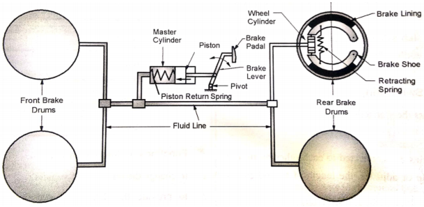
Figure: Hydraulib Braking System
4. Wheel Cylinder :
- In wheel cylinders, the high pressure brake fluid applies the force on the pistons of the wheel cylinders.
5.Brakes:
- The pistons of the wheel cylinder provide the actuating force for : (1) brake shoes in case of drum brakes ; or (ii) calipers in case of disk brakes.
- When brake is released, the piston return spring of the master cylinder pushes the piston in backward direction and fluid pressure inside the fluid line drops.
Internal Expanding Shoe Brake (Drum Brake):
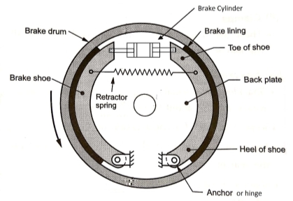
Figure: Intenal Expanding shoe brake
- The drum brake (internal expanding shoe brake), shown in Fig. consists of two shoes. The outer surface of the shoes are lined with some friction material.
- Each shoe is pivoted at one end about the hinge-pin and subjected to an actuating force at the other end. The actuating force on both the shoes is applied by a wheel (hydraulic) cylinder or a cam mechanism.
- When the actuating force is applied, the shoes are pressed against the rotating brake drum, thus causing the brake drum either to retard or stop completely.
- When the actuating force is released, the retracting spring return the brake shoes, so that they no longer contact the drum.
Application of drum brake :
- The drum brakes (internal expanding shoe brakes) are used in automobile vehicles (trucks, buses, cars, motorcycles, scooters, etc.).
Disc Brake
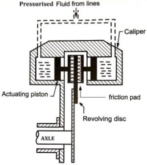
Figure: Disc Brake
- As shown in Figure, a disc brake consists of a cast iron disc bolted to the wheel hub and a stationary housing called caliper.
- The caliper is connected to some stationary part of the vehicle, like the axle casing or the stub axle and is cast in two parts, each part containing a piston.
- In between each piston and the disc, there is a friction pad held in position by retaining pins, spring plates etc.
- Passages are drilled in the caliper for the fluid to enter or leave each housing. These passages are also connected to another one for bleeding. Each cylinder contains a rubber sealing ring between the cylinder and the piston.
- When the brakes are applied, hydraulically actuated pistons move the friction pads into contact with the disc, applying equal and opposite forces on the later.
- On releasing the brakes, the rubber sealing rings act as return springs and retract the pistons and the friction pads away from the disc.
- We know that in case of Internal Combustion engines, combustion of air and fuel takes place inside the engine cylinder and hot gases are generated.
- The temperature of gases will be around 2300-2500°C. This is a very high temperature and may result into burning of oil film between the moving parts and may result into seizing or welding of the same.
- So, this temperature must be reduced to about 150-200°C at which the engine will work most efficiently.
- Too much cooling is also not desirable since it reduces the thermal efficiency. So, the object of cooling system is to keep the engine running at its most efficient operating temperature.
- It is to be noted that the engine is quite inefficient when it is cold and hence the cooling system is designed in such a way that it prevents cooling when the engine is warming up and till it attains to maximum efficient operating temperature, then it starts cooling.
- It is also to be noted that :
(a) About 20-25% of total heat generated is used for producing brake power (useful work).
(b) Cooling system is designed to remove 30-35% of total heat.
(c) Remaining heat is lost in friction and carried away by exhaust gases.
- There are mainly two types of cooling systems :
(a) Air cooling system
(b) Water cooling system
Air cooling system
- Air cooled system is generally used in small engines say up to 15-20 kW and in aero plane engines.
- In this system fins or extended surfaces are provided on the cylinder walls, cylinder head, etc.
- Heat generated due to combustion in the engine cylinder will be conducted to the fins and when the air flows over the fins, heat will be dissipated to air.
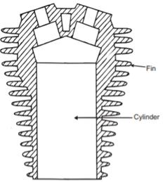
Figure: Air Cooling System
- The amount of heat dissipated to atmosphere depends upon :
(a) Amount of air flowing through the fins.
(b) Fin surface area.
(c) Thermal conductivity of metal used for fins.
Water Cooling System
- In water-cooling system, the water or coolant is used as a medium of cooling.
- The cylinder of I.C. Engine is surrounded by Water jacket.
- The water or coolant flows through the water jacket and absorbs the heat from cylinder.
- The hot water from engine jacket flows through theradiator. The radiator consists of header tank, collector tank and tubes with fins.
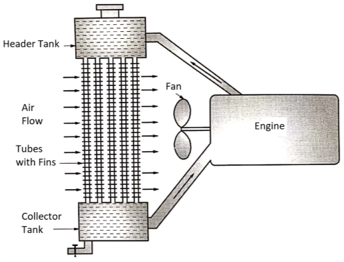
Figure: Water Cooling System
- The hot water or coolant flows through the radiator tubes where it loses its heat to air.
- The cold water or coolant is again supplied to engine jacket.
- The fan induces the air to flow over the radiator tubes, which helps to cool the coolant flowing through the radiator tubes.
- Application of water-cooling system: Water cooling system is highly effective. Hence, it is used in four wheelers.
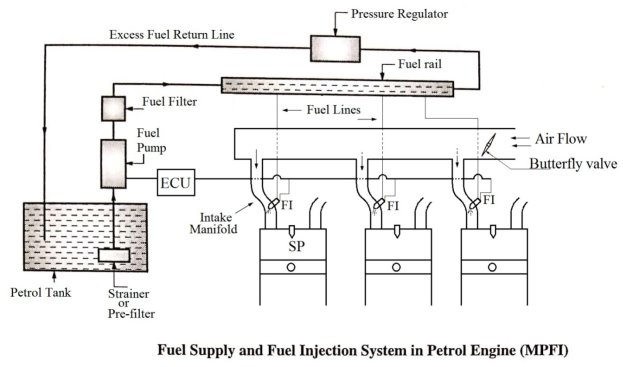
- Traditionally carburetor is an essential element of fuel supply system in petrol engine.
- It is now being replaced in petrol four-wheelers by multi-point fuel injection (MPFI) system.
- Various parts in the MPFI System are explained below.
1. Petrol Tank:
- Petrol is stored in petrol tank.
2.Fuel Pump:
- Fuel pump increases the pressure of the petrol before feeding it to the fuel rail. The fuel pump is driven by engine camshaft or electric motor.
3.Fuel Filter:
- The high pressure petrol passes through the fuel filter, where it is filtered so as to remove the dust and dirt particles.
4. Fuel Rail:
- The high pressure petrol is then supplied to the fuel rail.
5. Fuel Injector:
- A fuel injector is placed in intake manifold of each cylinder. The high pressure petrol enters the fuel injector and fuel injector injects the petrol into intake manifold at high velocity.
- The air is flowing though the intake manifold. The homogenous air and petrol mixture then enters the engine cylinder through the inlet valve.
6. Pressure Regulator:
- The pressure regulator controls the pressure of petrol in fuel rail.
7. Electronic Control Unit (ECU) :
- The ECU controls the fuel injection system. ECU decides the amount of fuel injected and timing of fuel injection in each cylinder.
FUEL SUPPLY AND FUEL INJECTION SYSTEM IN DIESEL ENGINE
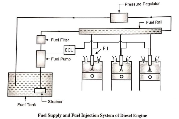
1. Diesel Tank:
- Diesel is stored in petrol tank.
2. Fuel Pump:
- The fuel pump increases the pressure of diesel before feeding it to the fuel rail. The fuel pump is driven by engine camshaft or electric motor.
3. Fuel Filter:
- The high pressure diesel passes through the fuel filter where it is filtered so as to remove the dirt particles.
4. Fuel Rail:
- The high pressure diesel is then supplied to the fuel rail.
5. Fuel Injector:
- The fuel injector is placed in a cylinder head of each cylinder. The high pressure diesel enters the fuel injector and the fuel injector injects the diesel into cylinder at the end of compression stroke.
6. Pressure Regulator:
- The pressure regulator controls the pressure of diesel in fuel rail.
7. Electronic Control Unit (ECU):
- The ECU controls the fuel injection system. It decides the amount of fuel injected and timing of fuel injection.
- The mechanism that transmits the power developed by the engine of automobile to the engine to the driving wheels is called the transmission system (or power train).
- It is composed of Clutch, gear box, Propeller shaft, Universal joints, differential and axle.
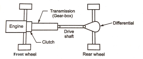
Figure: Transmission System
Functions or need of Transmission System
- Provide means of connection and disconnection of engine with rest of power train without shock and smoothly.
- Provide a varied leverage between the engine and the drive wheels
- Provide means to transfer power in opposite direction.
- Enable power transmission at varied angles and varied lengths.
- Enable speed reduction between engine and the drive wheels.
- Enable diversion of power flow at right angles.
- Provide means to drive the driving wheels at different speeds when required.
- Bear the effect of torque reaction, driving thrust and braking effort effectively.
- A clutch is a mechanism which enables the rotary motion of one shaft to be transmitted to second shaft, whose axis is coincident with that of first.
- The clutch is located between the engine and gear box when the clutch is engaged, the power flows from the engine to the rear wheels through the transmission system and the vehicle moves.
- When the clutch is disengaged, the power is not transmitted to the rear wheels and the vehicle stops while the engine is still running.
- The clutch is disengaged when
- Starting the engine
- Shifting the gears
- Stopping the vehicle
- Idling the engine
- The clutch is engaged only when the vehicle is to move and is kept engaged when the vehicle is moving.
Types of Friction Clutches
- Plate or Disk Clutches
- Single plate clutch (Dry clutch&Wet clutch)
- Multiplate clutch(Dry clutch & Wet clutch)
- Cone Clutches
- Centrifugal Clutches
Plate or Disk Clutches:
- The plate clutch consists of a set of driving plates and driven plates arranged alternately.Plate clutches are popular in automobiles.
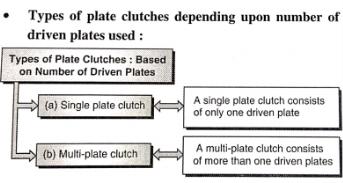
|
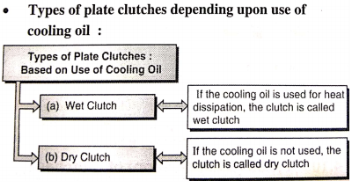
Cone Clutches:
- The cone clutch consists of cup keyed to the driving shaft and a cone with friction lining free to slide axially on the splined drive shaft.
Centrifugal Clutch:It works on the principal of centrifugal force.
Function of a Clutch
- To permit engagement or disengagement of a gear when the vehicle is stationary and the engine is running.
- To transmit the engine power to the road wheels smoothly without shock to the transmission system while setting the wheel in motion.
- To permit the engaging of gears when the vehicle is in motion without damaging the gear wheels.
Requirements of a Clutch
- It should be engage gradually to avoid sudden jerks.
- It should be easily operated (i.e it should consume minimum physical effort at the time of engagement and disengagement)
- It should be dynamically balanced (particularly required in case of high speed engine clutches)
- It should be free from slip when engaged.
- It should be as possible so that it will occupy minimum space.
- It should be easily accessible and have simple means of adjustment.
- It should be suitable mechanism to damp vibrations and to eliminated noise produced during the power transmission.
- It should be able to dissipate large amount of heat which is generated during the clutch operation due to friction.
SINGLE PLATE CLUTCH
- Components of Single Plate Clutch are
- One or Two Driving (Pressure) Plates
- One Driven (Friction) Plate
- Helical Compression Springs
- Disengagement Mechanism
- Driving (pressure) plate :
The driving plate is rigidly keyed to the driving shaft, while the driven plate is free to slide axially on the splined driven shaft. The driving plate is also known as pressure plate.
- Driven (friction) plate :
The friction lining, made of friction materials like asbestos, is either riveted or pasted to the driven plate. Thedriven plate is also known as friction plate or clutch plate.
- Helical compression springs :
- The helical compression spring exerts the axial force on the driven plate or friction plate or clutch plate.
- Disengagement mechanism :
The disengagement mechanism, which consists of disengagement sleeve, lever and clutch pedal, is used for disengaging the clutch.
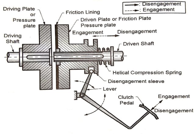
OR
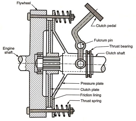
Figure: Single Plate Clutch
Working of Single Plate Clutch:
- The helical compression spring presses the driven plate (friction plate) against the driving plate (pressure plate). The spring creates an axial force between the driven plate (friction plate) and the driving plate (pressure plate).
- Frictional force between the two plates is responsible for transmitting the torque or power.
- Engaged condition:The torque is transmitted from driving shalt through key to the driving plate (pressure plate), from driving plate to the driven plate (friction plate) due to frictional force, and finally from driven plate through the splines to the driven shaft.
- Due to force exerted by the helical compression spring, the clutch is normally in engaged condition.
- In order to disengage the clutch, the clutch pedal is pressed downward, as shown in Fig. Due to this, the lever displaces the disengagement sleeve to the right.
- Disengaged condition:The spring force is neutralized by the external force applied on the disengagement sleeve. Hence, there is no axial pressure between the driving plate (pressure plate) and driven plate (friction plate); and there is no frictional force between the two contacting surfaces.
- Therefore, even though the driving shaft and driving plate are rotating, the driven plate and driven shaft are stationary; and there is no transmission of torque or power from the driving shaft to the driven shaft.
- The single plate clutches are used where large radial space is available such as : trucks, buses, cars, etc.
- Gear box receives the power from engine through clutch and transmits the power to the propeller shaft
- In gear box torque is increased and speed is reduced. Great box produces different speed ranges for the vehicle.
Need of Geer Box in Vehicles:
- In automobile vehicle the I.C. Engine operates at high speed but the torque produced by I.C. Engine is not very high.
- If I.C. Engine is directly connected to the wheels, the engine torque may not be enough to drive the vehicle.
- The gear box receives the power form engine at high speed. It reduces the speed and increases the torque, which is adequate to drive the vehicle.
- I.C. Engines operate over limited speed range. However, automobile vehicle has to run over the wide range of speeds and torque. The gear box provides wide range of speeds and torque to the vehicle.
Functions of Gear Box:
- Gear box reduces the speed and increases the torque.
- Gear box provides wide range of speeds and torque to the vehicle.
- With reverse gear, gear box provides the means to move the vehicle in reverse direction.
- In neutral position, the gear box disconnects the I.C. Engine from the wheel even with the clutch in the engaged position.
Types of Gear Box
- Sliding Mesh type gear box
- Constant Mesh type gear box
- Synchro Mesh type gear box
CONSTANT MESH GEAR BOX
- Components of Constant Mesh Gear Box are:
- Input Shaft (Clutch Shaft)
- Output Shaft (Main Shaft)
- Lay Shaft (Counter Shaft)
- Gears (A1, A2, B1, B2, C1, C2, D1, D2)
- Dog Clutches (S1, S2)
- Gear Shifting Mechanism
- Input Shaft (Clutch Shaft) :
- The input shaft of gear box is connected to the engine through clutch. It receives the power at high speed and low torque) from the engine.
- Output Shaft (Main Shaft):
- The output shaft of the gear box is connected to the propeller shaft through the universal joint. It transmits power (at low speed and high torque) to the propeller shaft. It is a splined shaft.
- The gears B1, C1 and D1 are free to rotate on this shaft. The dog clutches S1 and S2 can slide axially on this shaft.
- Lay Shaft (Counter shaft) :
- The lay shaft is a shaft parallel to input and output shafts. The gears A2, B2, C2 and D2 are rigidly mounted on it.
- Gears :
- Gear A1 is mounted on input shaft and it is constantly in engagement with gear A2 mounted on the lay shaft.
- Gears A2, B2, C2 and D2 are rigidly mounted on the lay shaft.
- Gears B1, C1 and D1 are free to rotate on splined output shaft.
- Dog Clutches :
- The dog clutches S1 and S2 are free to slide axially on splined shaft. The dog clutch S1 can engage with gear A1 orgear B1.
- Similarly the dog clutch S2 can engage with gear C1 or gear D1.
- Gear Shifting Mechanism :
- Thegear shifting mechanism is operated by gear lever to shift or change the gears.
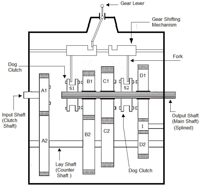
Figure: Constant Mesh Gear Box
Working of Constant mesh Gear Box
- In this type of gearbox, all the gears of the main shaft are in constant mesh with corresponding gears of the countershaft.
- The gears on the main shaft which are bushed are free to rotate. The dog clutches are provided on main shaft. The gears on the lay shaft are, however, fixed.
- When the left Dog clutch is slid to the left by means of the selector mechanism, its teeth are engaged with those on the clutch gear and we get the direct gear.
- The same dog clutch, however, when slid to right makes contact with the second gear and second gear is obtained.
- Similarly movement of the right dog clutch to the left results in low gear and towards right in reverse gear.Usually the helical gears are used inconstant mesh gearbox for smooth and noiseless operation.
- 1st gear :
- To engage 1stgear, dog clutch S2 is shifted to left to engage with gear C1.
- Power flow: Input Shaft - Gear A1- Gear A2- Lay Shaft - Gear C2 - Gear C1 — Dog Clutch S1- Output Shaft.
- 2nd Gear:
- To engage 2ndgear, dog clutch S2 is shifted to right to disengage from gear C1 and dog clutch S1 is shifted to right to engage with gear B1.
- Power flow: Input Shaft - Gear A1- Gear A2- Lay Shaft - Gear B1 - Gear B2- Dog Clutch S1 - Output Shaft.
- 3rd gear :
- To engage 3rd gear, dog clutch S1 is shifted to left to engage with gear A1.
- Power flow: Input Shaft - Gear A1 — Dog Clutch S1- Output Shaft.
- Reverse Gear :
- To engage reverse gear, dog clutch S1 is shifted to right to disengaged from gear A1 and dog clutch S2 is shifted to right to engage with gear D1.
Gear ratio (speed ratio) of gear box:
- Gear ratio speed ratio of gear box is the ratio of speed of input shaft (engine shaft) to the speed of output shaft (propeller shaft).
- Let,
- Ni = speed of input shaft of gear box (r.p.m.)
- No = speed of output shaft of gear box (r.p.m.)
- I = gear ratio or speed ratio

- The gear ratio (speed ratio) of gear box is different in different gears. It is maximum in 1st gear and minimum in last gear.
Power Transmission Capacity of Gear Box:
- Let,
- Pi= input power to gear box (engine power), Watt
- Po = output power of gear box (propeller shaft power), Watt
- Ti = input torque to gear box (enginetorque), N-m
- To output torque of gear box, (propeller shaft torque), N-m
- Input power


- Output power


- Efficiency of Gear Box

- If Efficiency of Gear Box is 100 %, i.e.
 , then


- Propeller shaft is connecting the drive from gear box to final drive. Hence it is also called Drive Shaft.
- It is the group of parts connecting the transmission with the drive wheels.
- It consists of propeller shaft (also called Drive Shaft), Universal Joints/Constant Velocity Joints and Slip Joints.
- Shaft: As this must withstand torsional loads, it is usually made of tubular cross-section. It also has to be well balanced to avoid whirling at high speeds. Shafts are made of steel, aluminum or composite materials.
- The rotational motion of the gear box main shaft is transferred to the differential unit for rotating the drive wheels.
- Universal Joint: One or two universal joints, depending upon the type of rear axle drive used. The universal joints account for the up and down movements of the rear axle when the vehicle is running.
- Universal joint is provided to transmit the power at changing angles of the propeller shaft, while vehicle isrunning.
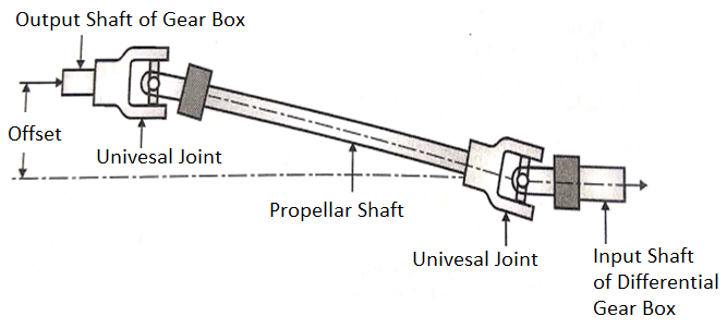
Figure: Propeller Shaft
- A universal joint allows driving torque to be carried through two shafts that are at an angle with each other.
- A simple universal joint consist two Y- shaped yoke, one on the driving shaft and other on the driven shaft. The four arms of spider are assembled in needle bearings in the two yokes.
- The driving shaft and yoke force the spider to rotate. The other two trunnions of the spider then cause the driven yoke to rotate.
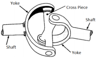
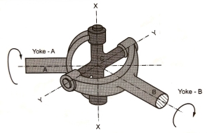
Figure: Universal Joint
- When the two shafts are at an angle with each other, the needle bearings permit the yokes to swing around on the trunnions with each revolution.
- A simple universal joint does not transmit the motion uniformly when the shafts are operating an angle. Because of this, two universal joints are used in a vehicle, one between the gear box and the propeller shaft and other between the propeller shaft and the differential pinion shaft.
DIFFERENTIAL GEAR BOX
Differential gear box transmits the power from the propeller shaft to the shaft of rear axle.
Functions of Differential Gear Box
1. The shaft of rear axle is at right angles to the propeller shaft. The differential gear box transmits the power at right angles.
2. The differential gear box allows the two wheels to rotate at different speeds when vehicle is taking the turn.
3. The differential gear box increases the torque and reduces the speed from propeller shaft to rear axle shaft.
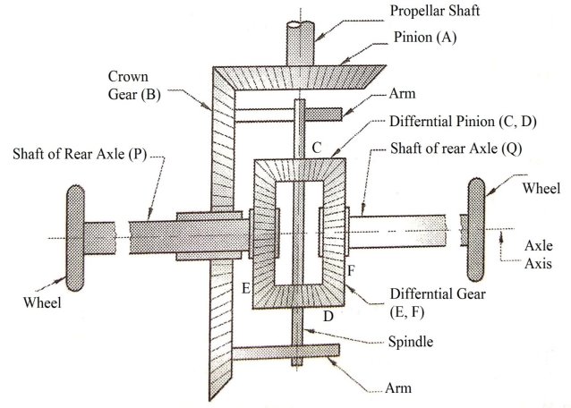
Differential Gear Box
Working of Differential Gear Box
- When the automobile runs on a straight path, the differential gears E and F and differential pinions C and D acts as one unit and rotates with the crown gear B. Hence, the differential gears E and F rotate with the same speed and in the same direction as that of crown 0-gear B. There is no relative motion between C, D, E and F. The differential pinion C and D do not rotate about their own axes.
- When automobile is taking right turn, the inner rear wheel (i.e. gear F which is keyed to the rear axle Q) should have lesser speed than the outer rear wheel (i.e. gear E which is keyed to the rear axle P). Due to relative speed of the inner and outer differential gears F and E, the pinion C and D start rotating about the spindle axis and at the same time revolve about the rear axle axis also. Due to this epicycle effect, the speed of the inner rear wheel (gear F) is decreases by a certain amount and the speed of outer rear wheel (gear E) increases by the same amount.
It is the axle where the motion from the propeller shaft is transferred. In case of four wheel drive, the motion is transferred to both the axles and therefore both the axles are 'live' axles. When motion is transferred to one axle the other axle is termed as 'dead' axle. The dead axle only carries the weight of the vehicle.
The live axle performs the following two functions:
- It acts as a beam and through the suspension springs carries the load due to the weight of the carriage unit. It transmits these loads under dynamic conditions through the road wheels to the ground.
- It also supports and accommodates the final drive, differential and shafts.
Front Axle:
- Front axle is used for steering the front wheels carried on the stub axle. It is the major component of a vehicle designed to transmit the vehicle weight to the front steering wheels through the front suspension system. Fig. Shows a conventional front axle.
- The front axle has to take vertical vehicle load, bending loads due to weight, and torque loads due to braking and acceleration.
- To withstand the above loads, the axle is made of section in the central portion while the ends are made elliptical.
Rear Axle:
- Rear axle drives are employed on front engine rear wheel drive vehicles.
- The rear axle drive system consists of important sub-systems such as universal joints, slip joint, propeller shaft, suspension leaf springs, rear axle, rear axle casing, final drive and differential.
- The rear axle drive system is subjected to the following forces and torques.
Need of Safety:
- Vehicles are driven for long distances, at high speeds, with heavy loads and other adverse conditions.
- It is hence important to ensure safety of passengers inside the vehicle, pedestrians on the road and the luggage carried by the vehicle.
- Vehicle safety is the study and practice of design, construction, equipment and regulation to minimize the occurrence and consequences of automobile.
Active Safety System:
- Active safety systems are those that improve driving safety through technology designed to prevent accidents before they happen.These are technology systems assisting in the prevention of an accident.
- They are also referred as primary safety system. Active safety systems use an understanding of the state of the vehicle to both avoid and minimize the effects of a crash.
- The modem vehicle has various electronic sensors and microprocessor controlled actuators that assist driver to have better control on the vehicle.
- These forward-looking technologies are expected to play an increasing role in accident avoidance and mitigation.
- Examples of active safety systems are :
- ABS - Antilock Braking System
- TCS - Traction Control System
- ESP - Electronic Stability Program
- Cruise Control
- Tyre Pressure Monitoring system
- Night Vision System
- Anti-lock Braking System
- Antilock braking systems (ABSs) are electronic systems that monitor and control wheel slip during vehicle braking.
- ABS can improve vehicle control during braking and reduce stopping distances on slippery road surfaces by limiting wheel slip and minimizing lockup. Reducing wheel slip improves vehicle stability and control during braking, since stability increases as wheel slip decreases.
Working Principle of ABS
- This system consists of a central (ECU) Electronic Control Unit and four-wheel speed sensors connected to each wheel and two hydraulic valves. There is a valve in the brake line of each brake controlled by the ABS.
- The valve has three positions:
- 1st- The valve is open; pressure from the master cylinder is passed right through to the brake.
- 2nd- The valve blocks the line, isolating that brake from the master cylinder.
- 3rd - In position three, the valve releases some of the pressure from the brake.
- When the ECU finds that any wheel is turning faster than the other wheel, automatically brake hydraulic pressure to the affected wheel is increased by the ABS system so that braking force is reapplied, and the wheel slows down.
- This complete process performed by the ABS is repeated continuously throughout the drive on mostly uneven roads and can be easily detected by the driver of the car with the help of brake pedal pulsation.
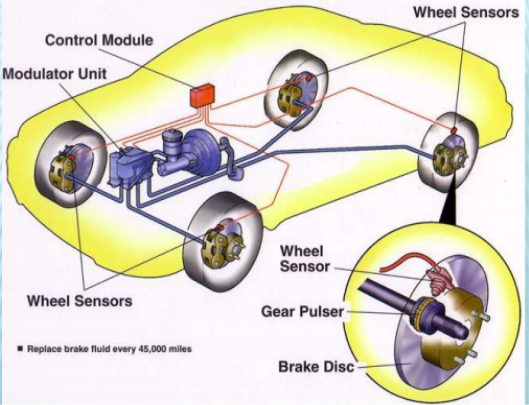
- The wheel speed sensors continuously monitor the speed of each wheel and transmit this information to electronic control unit.
- If wheel is about to lock under heavy braking, the hydraulic control valve reduces the braking pressure of that single wheel until the threat of locking is past.
- Once the wheel turns freely, the braking pressure is again increased. This increase and decrease of braking pressure continues until driver reduces the force applied on brake pedal or until the tendency of lock is overcome.
ABS Components
Hydraulic Components:
1. Accumulator: It is used to store hydraulic fluid to maintain high pressure.
2. Antilock hydraulic control valve assembly: It controls the release and application of the brake system pressure.
3. Booster pump: It is used to provide pressurized hydraulic fluid.
4. Booster/Master Cylinder Assembly: It is needed to modulate hydraulic pressure in the wheel circuit.
5. Fluid Accumulator: It temporarily stores brake fluid that is removed from the wheel brake.
6. Main Valve: This is a two-position valve and is open only in the ABS mode.
7. Modulator Unit: It controls the flow of pressurized brake fluid to the individual wheel circuits.
8. Solenoid Valves: It is in the modulator unit and are electrically operated by signals from the control module.
Electrical / Electronic components:
1. ABS control module: It monitors system operation and controls antilock function when needed.
2. Brake pedal sensor: Its function is to switch on the brake lights to alert other vehicles that the car is slowing down and/or is going to stop.
3. Wheel speed sensor: These are generally used for sensing the wheel speed.
Advantages of ABS
- It allows the driver to maintain directional stability and control over steering during braking.
- Safe and effective.
- Automatically changes the brake fluid pressure at each wheel to maintain optimum brake performance.
- ABS absorb the unwanted turbulence shock waves and modulates the pulses thus permitting the wheel to continue turning.
Disadvantage of ABS
- It is very costly.
- Maintenance cost of a car equipped with ABS is more.
Passive Safety System:
- Passive safety systems are those that protect passengers once an accident has occurred, by reducing risk and severity of injury.
- These are technology systems for reducing impact of crash on passengers.
- They are also referred as secondary safety system.
- These systems are only deployed or effective response to a vehicle accident.
- Examples of passive safety systems are:
- Seatbelt
- Pretensioners
- Airbag - front and side airbags
- Seat Belt:
- A seat belt is a safety harness designed secures the occupant of a vehicle against harmful effects resulting during a collision or a sudden stop.
- The seat belt is sometimes also referred as safety belt.
- A seat belt reduces the likelihood and the injury in a traffic collision by stopping the vehicle occupant from hitting hard against interior elements of the vehicle or other passengers.
- The seat belt keeps the occupant positioned correctly on its seat for maximum benefit from the impact.
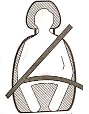
Figure: Seat Belt
Need for seat belt
- Seat Belts (Safety Belts) is a safety system designed to secure the passengers against harmful and dangerous movements arising out of collision or sudden stop of vehicle.
- When passenger and vehicle are travelling at same speed. The seat belt is fairly loose and passenger can make comfortable movements. When the driver applies the brake and stops the vehicle suddenly or when vehicle stops suddenly due to collision, due to inertia, the seat belt applies opposite force on the driver and passengers to prevent them from hitting against interior part of the vehicle or falling out of the vehicle through windshield.
2. Seat
- A car seat is the seat used in automobiles. Most of the car seats are made from inexpensive but durable material to withstand prolonged use.
- The commonly used material for seats is polyester. In latest cars the arrangement of seat is bucket type.
- It is a separate seat with encountered platform designed to accomodate one person distinct from a bench seat i.e. a platform designed to seat upto three people.
- Individual bucket seats typically have rounded backs and may offer a variety of adjustments to fit different passangers.
- Some sedan models offer fold-down rear seats to gain cargo space when they are occupied by passangers.
- According to motor vehicle safety act the seats should be properly anchored and the construction of automobile seats should be proper.
- In addition to this, the act also includes that a child to sit up front is should be 5 feet and they must weight upto 40 kg.
- Side airbags are often built right into the side of the seat.
- Some modern cars like BMW, Audi, Benz etc. are equipped with a battery powered automatic control to adjust how the seat sits into a car.
- Some vehicle let the driver save the adjustments in memory (memory seat) for later recall with the push of a button.
- Car seat covers are accessories that protect the original seat from wear and tear.
- It also add a custom look to a vehicle's interior. This can maintain the resale value of the car and maximize the comfort of the driver and passangers.
3. Air Bags
- The airbag was invented to perform as a safety cushionbetween the passangers and the hard surfaces of the car.
- It is also referred as Supplemental Restraint System (SRS), Air Cushion Restraint System (ACRS) and Supplemental Inflatable Restraint (SIR).
- It consists of a flexible envelope designed to inflate rapidly during an automobile collision.
- Its purpose is to cushion occupants during a crash and provide protection to their bodies when they strike interior objects such as the steering wheel or a window.
- The airbag is designed to only inflate in moderate to severe frontal crashes.
- Airbags are normally designed with the intention of supplementing the protection to an occupant who is correctly restrained with a seatbelt.
- Most designs are inflated through pyrotechnic means and can only be operated once.
- This airbag inflation is controlled by the Airbag Electronic Control Unit (AECU). After deployment, the inflated airbags need to be replaced and the ECU usually needs to be reset.
- Components of Airbag system The major components of airbag system are Crash sensors, Airbag Electronic Control Unit (AECU), Detonator and Inflatable airbag.
References:
1. Khan, B. H., “Non Conventional Energy Sources, Tata McGraw-Hill Publisher Co. Ltd.
2. Boyle, Godfrey, “Renewable Energy”,2nd Ed., Oxford University Press
3. Khurmi, R.S. ,and Gupta, J. K.,“A Textbook of Thermal Engineering”, S. Chand & Sons
4. Incropera, F. P. And Dewitt, D.P., (2007), “Fundamentals of Heat and Mass Transfer, 6th Ed., John Wiley and Sons, USA
5. Groover,Mikell P., (1996), “Fundamentals of Modern Manufacturing: Materials, Processes, and Systems”, Prentice Hall, USA
6. Norton, Robert L., (2009), “Kinematics and Dynamics of Machinery”, Tata McGrawHill
7. Cleghorn, W. L., (2005), “Mechanisms of Machines”, Oxford University Press
8. Juvinal, R. C., (1994), “Fundamentals of Machine Component Design”, John Wiley and Sons, USA
9. Ganeshan, V., (2018), “Internal Combustion Engines”, McGraw Hill
10. Anderson, Curtis Darrel and Anderson,Judy, (2010), “Electric and Hybrid Cars: A History”, 2nd Ed., McFarland