Unit 1
Introduction
Distributed System is a collection of multiple computers which are linked by the network to produce an integrated computing facilities. It may be the Local Area Network (LAN), Metropolitan Area Network (MAN) or Wide Area Network (WAN).
A distributed system is a collection of independent computers that appears to its users as a single coherent system.
The size of Distributed System is vary from number of devices. The interconnection of network may be wired, wireless or combination of both.Distributed systems are often highly dynamic, in the sense that computers can join and leave, with the topology and performance of the underlying network almost continuously changing.
Following figure shows the example of Distributed System.
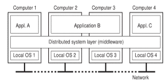
Fig 1.1-A Distributed System organized as middleware.
Fig. 1.1 shows four networked computers and three applications, of which application B is distributed across computers 2 and 3. Each application is offered the same interface
Fowling are the key goals of Distributed System.
1) Making Resources Accessible
The main goal of a distributed system is to make it easy for the users and applications to access remote resources, and to share them in a controlled and efficient way. Resources can be printers, computers, storage facilities, data, files, Web pages, and networks.
There are many reasons for wanting to share resources but an important reason is that of economics. For example instead of buying and maintain a separate printer for each user in small office it is cheaper to share the printer among users.
Connecting users and resources also makes it easier to collaborate and exchange information, and it is successfully made by the internet by using simple protocols such as http, ftp etc. for exchanging the files, mail, Documents, audio and video.
2) Transparency
An important goal of a distributed system is to hide the fact that its processes and resources are physically distributed across multiple computers.
It is used to achieving the image of a single system image without concealing the details of the location, access, migration, concurrency, failure, relocation, persistence and resources to the users.
Types of Transparency
The concept of transparency can be applied to several aspects of a distributed system, following fig shows different types of transparency.
Transparency | Description |
Access | It hide difference in data representation and how data is accessed. |
Location | It hide where a resource is located in the system. |
Migration | It hide that a resources may move to another location. |
Relocation | It hide that a resource may be moved to another location while in use. |
Replication | It hide that a resource is replicated. |
Concurrency | It hide that the resource may be shared by several competitive users. |
Failure | It hide the failure and recovery of resource. |
Fig 1.2. Different forms of transparency in a distributed system
Access transparencyis used for hiding differences in data and its representation and the way that resources can be accessed by users. In this we want to hide differences in machine architecture but it is more important that finds the how data is represented by different machines and operating systems.
For example in distribute systems there are different computer systems and that are run on different operating system with different file naming conventions. Because of this the access transparency can be achieved and files can be hidden from the user and applications.
Location transparency refers to the fact that users cannot tell where a resource is physically located in the system. Naming plays an important role in achieving location transparency.
Location transparency can be achieved by assigning only logical names to resources. The names in which the location of a resource is not secretly encoded. For example such name is URL https://www.shreeclass.com/index.html it doesn’t give any idea about where the index.html file is located on machine.
Distributed systems in which resources can be moved without affecting on the other resources those resources can be accessed are said to provide migration transparency.
There is situation in which resources can be relocated while they are being accessed without the user or application noticing anything. In such cases, the system is said to support relocation transparency.
An example of relocation transparencyis when mobile users can continue to use their wireless laptops for the internet and while moving from one place to another place without ever being disconnected the network connection.
When two independent users may each have stored their files on the same file server or may be accessing the same tables in a shared database. In such cases, it is important that each user does not notice that the other is making use of the same resource. This is called as concurrency transparency.
3) Openness
Another important goal of distributed systems is openness. An open distributed system is a system that offers services according to standard rules that describe the syntax and semantics of those services.
For example, in computer networks, standard rules govern the format, contents, and meaning of messages sent and received. Such rules are made up within protocols. In distributed systems, services are generally specified through interfaces, which are often described in an Interface Definition Language (IDL).
It Make the network easier to configure and modify component structure.
4) Reliability
Compared to a single system, a distributed system should be highly capable of being secure, consistent and have a high capability of masking errors.
5) Performance
Compared to other models, distributed models are expected to give a much-wanted boost to performance.
6) Scalability
Worldwide connectivity through the Internet is rapidly becoming as common as being able to send a postcard to anyone anywhere around the world. With this in mind, scalability is one of the most important design goals for developers of distributed systems
Scalability of a system can be measured along at least three different dimensions that is geography, administration or size.
1) Size
The system can be scalable with respect to size that means we can easily add more number of users and resources to the system.
2) Geography
In this scalable system the users and resources may lie far apart.
3) Administration
A system can be administratively scalable that it can still be easy to manage even if it spans many independent administrative organization.
Distributed System can be divided into three types that is Distributed Computing System, Distributed Information System and Distributed Pervasive System.
1) Distributed Computing Systems
An important class of distributed systems is the one used for high-performance computing tasks. It can be divided between two subgroups as Cluster Computing System and Grid Computing System.
In cluster computing the underlying hardware consists of a collection of similar workstations or PCs, closely connected by means of a high speed local-area network.
The situation becomes quite different in the case of grid computing. This subgroup consists of distributed systems that are often constructed as a federation of computer systems, where each system may fall under a different administrative domain, and may be very different when it comes to hardware, software, and deployed network technology.
- Cluster Computing System
Cluster computing system is more popular when the price/performance ratio of personal computer and workstations improved.
At a certain point, it became financially and technically attractive to build a supercomputer using off-the-shelf technology with collection of simple computes and high speed network.
Cluster computing system is used for parallel programing in which a single program is run in parallel on multiple computers.
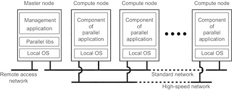
Fig 1.3 Example of Cluster operating system.
The above figure shows Linux-based Beowulf clusters, of which the general configuration is shown in fig. Each cluster consists of a collection of compute nodes that are accessed and controlled by single master node.
The master node handles the allocation of nodes to a particular parallel program, maintains a batch queue of submitted jobs and provide interface for the user of the system.
The master noderuns the middleware needed for the execution of programs and management of the cluster, while the compute nodes often need nothing else but a standard operating system.
An important part of this middleware is formed by the libraries for executingparallel programs. These libraries effectively provide only advanced message-based communication facilities, but are not capable of handling faulty processes, security, etc.
As an alternative to this hierarchical organization, a symmetric approach isfollowed in the MOSIX system. MOSIX attempts to provide a single-system image of a cluster, meaning that to a process a cluster computer offers the ultimate distribution transparency by appearing to be a single computer.
B. Grid Computing System
A characteristic feature of cluster computing is its homogeneity in contrast the grid computing system have a high degree of heterogeneity with no assumptions are made concerning hardware, operating system, networks, administrative domain, security policies etc.
A key issue in a grid computing system is that resources from different organizations are brought together to allow the collaboration of a group of people or institutions. Such a collaboration is realized in the form of a virtual organization.
The people belonging to the same virtual organization have access rights to the resources that are provided to that organization. The resources consists of compute servers, storage facilities and databases.
The grid computing system provides access to resources from different administrative domains and the users which are belonging to the virtual organization.
Following figure shows the layered architecture of grid computing system.

Fig 1.4 A layered architecture for grid computing system.
The architecture consist of five layers such as fabric layer, connectivity layer, Resource layer, Collective layer and Application layer.
- Fabric Layer
The lowest layer is fabric layer it provides interface to local resources at a specific site these resources are fitted to allow sharing of resources in virtual organization. They also provide the functions for querying the state and capabilities of resources.
2. Connectivity layer
This layer consist of communication protocol for supporting grid transactions that span the usage of multiple resources. For example when protocols wants to transfer he data between the resources or access data from remote location in this situation the connectivity layer will contain security protocols to authenticate users and resources.
3. Resource layer
This layer is responsible for managing the single resource. It uses the functions provided by the connectivity layer and calls directly the interfaces made available by the fabric layer.
For example this layer provides the function for to perform specific operations such as creating a process or reading data. The resource layer is responsible for access control hence authentication is provided by connectivity layer.
4. Collective layer
This layer deals with handling access to multiple resources and typically consists of services for resource discovery, allocation and scheduling of tasks onto multiple resources, data replication.
Unlike the connectivity and resource layer, which consist of a relatively small, standard collection of protocols, the collective layer may consist of many different protocols for many different purposes, reflecting the broad spectrum of services it may offer to a virtual organization.
5. Application layer
This is the last layer of grid computing system. It consists of the applications that operate within a virtual organization and which make use of the grid computing environment.
The collective, connectivity and resource layer are the grid middleware layer.These layers jointly provide access to and management of resources.
2) Distributed Information System
The distribute information system more helpful in organization for their networked applications. The network application consist of server running that application including a database and making it available to remote programs, called clients.
Such clients could send a request to the server for executing a specificoperation, after which a response would be sent back. Integration at the lowest level would allow clients to wrap a number of requests, possibly for different servers, into a single larger request and have it executed as a distributed transaction. The key idea was that all, or none of the requests would be executed.
As applications became more sophisticated and were gradually separated into independent components it became clear that integration should also take place by letting applications communicate directly with each other.
These are two forms of distribute information system.
- Transaction Processing system
- Enterprise Application Interface
- Transaction Processing System
The operation on database are carried out in the form of transaction. To perform programming using transaction we require special primitives that must be supplied by distributed system or language runtime system. Following figure shows the primitives in transaction. The list of primitives depends on what kind of objects are being used in the transaction.
In a mail system, there might be primitives to send, receive, and forward mail. In an accounting system primitive might be READ and WRITE. Ordinary statements, procedure calls are also allowed inside a transaction. Remote procedure calls (RPCs) is procedure calls to remote serversare also used in a transaction which is known as a transactional RPC.
Primitive | Description |
BEGIN_TRANSACTION | Make the transaction start |
END_TRANSACTION | Terminate the transaction and try to commit |
ABORT_TRANSACTION | Kill the transaction and restore the old value |
READ | Read the data from table or file |
WRITE | Write a data to a file or table |
Fig 1.5 List of primitives in transaction
BEGIN_ TRANSACTION and END_TRANSACTION are used to delimit thescope of a transaction. The operation performed between them is the body of transaction. The feature of transaction is either all this operations are executed or none of them executed. ACID is the property of transaction it consist of
- Atomicity: To the outside world, the transaction happens indivisibly.
- Consistency: The transaction does not violate system invariants.
- Isolation: Concurrent transactions do not interfere with each other.
- Durability: Once a transaction commits, the changes are permanent.
The first property is the transaction is Atomic that means each transaction happens completely or not. While transaction is in progress, other processes cannot see any of the intermediate states.
The second property says that the transaction is consistent. It means if the system has certain invariants that must always hold, if they held before the transaction, they will hold afterward too.
The third property says that transactions are isolated or serializable. It means if two or more transactions are running at the same time, to each of them and to other processes, the final result looks as though all transactions is an sequentially in some order.
The fourth property is transactions aredurable. It refers to the fact that once a transaction commits, no matter what happens, the transaction goes forward and the results become permanent. No failure after the commit can undo the results or cause them to be lost.
The transaction is defined on single database and nested transaction is constructed from a number of sub transactions. Fig 1.6 shows the creation on nested transaction in system. The top-level transaction may fork off children that run in parallel with one another, on different machines, to gain performance or simplify programming. Each of these children may also execute one or more sub transactions, or fork off its own children.
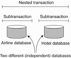
Fig 1.6 nested transaction.
Nested transactions are important in distributed systems, for they provide a natural way of distributing a transaction across multiple machines. They follow a logical division of the work of the original transaction.
For example, a transaction for planning a trip by which three different flights need to be reserved can be logically split up into three subtransactions. Each of these sub transactions can be managed separately and independent of the other two.
In the early days of enterprise middleware systems, the component that handleddistributed (or nested) transactions formed the core for integrating applications at the server or database level.
This component was called a transaction processing monitor or TP monitor for short. Its main task was to allow an application to access multiple server/databases by offering it a transactional programming model, as shown in Fig. 1.7.
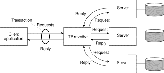
Fig 1.7 a role of TP monitor in distributed system
B. Enterprise Application Interface
The more applications became decoupled from the databases they were built upon, the more evident it became that facilities were needed to integrate applications independent from their databases. In application components should be able to communicate directly with each other and not merelyby means of the request/reply behavior that was supported by transaction processingsystems.
This need for inter-application communication led to many different communicationmodels. The main idea was that existing applications could directly exchange information, as shown in Fig. 1.8.
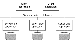
Fig 1.8 communication facilitator in enterprise application integration.
There are several types of communication middleware exist with remote procedurecalls (RPC).An application component can effectively send a request to another application component by doing a local procedure call, which results in the request being packaged as a message and sent to the callee. Likewise, the result will be sent back and returned to the application as the result of the procedure call.
As the popularity of object technology increased, techniques were developed to allow calls to remote objects, leading to what is known as remote method invocations (RMI). An RMI is essentially the same as an RPC, except that it operates on objects instead of applications. RPC and RMI have the disadvantage that the caller and callee both need to be up and running at the time of communication. In addition, they need to know exactly how to refer to each other.
This tight coupling is often experienced as a serious drawback, and has led to what is known as message-oriented middleware, or simply MOM. In this case, applications simply send messages to logical contact points, often described by means of a subject.
Likewise, applications can indicate their interest for a specific type of message, after which the communication middleware will take care that those messages are delivered to those applications. These so-called publish/subscribe systems form an important and expanding class of distributed systems.
The organization of distributed systems is mostly about the software componentsthat constitute the system. These software architectures tell us how the various software components are to be organized and how they should interact.
In distributed system different architectural styles are present for successful development of large systems. The styles are important in terms of components, the way that components are connected to each other, the data exchanged between components and how these elements are jointly configured into a system.
Following are the most important architecture for distributed system.
- Layered Architectures
- Object-based Architecture
- Data-centered Architecture
- Event based Architecture
- Layered Architecture
It is simple layered style in this components are organized in a layered fashion where a component at layer L; is allowed to call components at the underlying layer Li, but not the other way around, as shown in Fig 1.9.
This model has been widely adopted by the networking community. A key observation is that control generally flows from layer to layer: requests go down the hierarchy whereas the results flow upward.
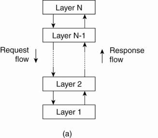
Fig .1.9 Layered architecture
2. Object based Architecture
Some organization follow the object based architecture in which each object corresponds to what we have defined as a component, and these components are connected through a (remote) procedure call mechanism.
The layered and object based architectures still form the most important styles for large software systems.
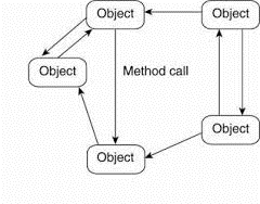
Fig 1.10 Object based architecture
3. Data-centered Architecture
Data-centered architectures evolve around the idea that processes communicate through a common passive or active repository. It can be argued that for distributed systems these architectures are as important as the layered and object-based architectures.
For example, a wealth of networked applications have been developed that rely on a shared distributed file system in which virtually all communication takes place through files.
4. Event based Architecture
In event-based architectures, processes essentially communicate through the propagation of events, which optionally also carry data, as shown in Fig. 1.11.
For distributed systems, event propagation has generally been associated with what are known as publish/subscribe systems. The basic idea is that processes publish events after which the middleware ensures that only those processes that subscribed to those events will receive them.
The main advantage of event-based systems is that processes are loosely coupled. In principle, they need not explicitly refer to each other. This is also referred to as being decoupled in space, or referentially decoupled.
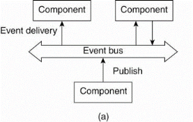
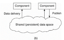
Fig 1.11 Event based and shared data-space architecture.
Event-based architectures can be combined with data-centered architectures, which is also known as shared data spaces. The essence of shared data spaces is that processes are now also decoupled in time: they need not both be active when communication takes place.
System architecture is depends on where software components are placed. Deciding on software components, their interaction, and their placement leads 10 an instance of a software architecture, also called a system architecture.
- Centralized Architecture
In the basic client-server model, processes in a distributed system are divided into two parts. A server is a process implementing a specific service, for example, a file system service or a database service. A client is a process that requests a service from a server by sending it a request and subsequently waiting for the server's reply. This client-server interaction, also known as request-reply behavior is shown in Fig.


Fig. 1.12 General interaction between client and server
Communication between a client and a server can be implemented by using simple connectionless protocol such as UDP. In these cases, when a client requests a service, it simply packages a message for the server, identifying the service it wants, along with the necessary input data.
The message is then sent to the server. The latter, in turn, will always wait for an incoming request, subsequently process it, and package the results in a reply message that is then sent to the client.
Using a connectionless protocol has the obvious advantage of being efficient. As long as messages do not get lost or corrupted, the request/reply protocol just sketched works fine.
As an alternative, many client-server systems use a reliable connection-oriented protocol. Although this solution is not entirely appropriate in a local-area network due to relatively low performance, it works perfectly in wide-area systems in which communication is inherently unreliable.
Application layering
The client server model has multiple issues one of these is how to draw clear distinction between client and server.Considering that many client-server applications are targeted toward supporting user access to databases, many people have advocated a distinction between the following three levels.
- User interface level
- Processing level
- Date level
The user-interface level contains all that is necessary to directly interface with the user, such as display management. The processing level typically contains the applications.
The data level manages the actual data that is being acted on. Clients typically implement the user-interface level. This level consists of the programs that allow end users to interact with applications. There is a considerable difference in how sophisticated user-interface programs are.
The simplest user-interface program is nothing more than a character-based screen. Such an interface has been typically used in mainframe environments.
For example, consider an Internet search engine. Ignoring all the animated banners, images the user interface of a search engine is very simple: a user types in a string of keywords and is subsequently presented with a list of titles of Web pages.
The back end is formed by a huge database of Web pages that have been pre-fetched and indexed. The core of the search engine is a program that transforms the user's string of keywords into one or more database queries.
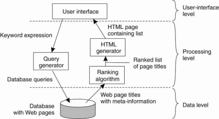
Fig 1.13 the simple organization of an internet search engine into three layers.
Multitiered Architecture
To implement client-server architecture require more number of computers. The simplest organization have two types of machines:
- A client machine containing only the programs implementing the user-interface level.
- A server machine containing the rest, that is the programs implementing the processing and data level
In this organization everything is handled by the server while the client is essentially no more than a dumb terminal. One approach for organizing the clients and servers is to distribute the programs in the application layers of the previous section across different machines.
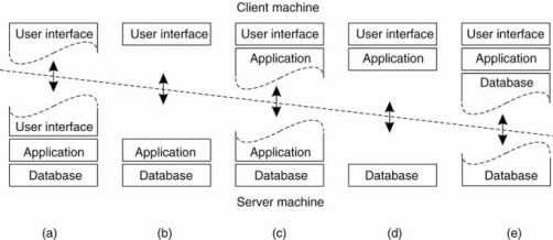
Fig 1.14 shows the Alternative Client-Server architecture a-e
Figure (a) shows the terminal dependent part of the user interface on the client machine and give the applications remote control over the presentation of their data.
Figure (b) shows the user-interface software on the client side. In such cases, we divide the application into a graphical front end, which communicates with the rest of the application which is on server through an application-specific protocol.
In this model, the front end (the client software) does no processing other than necessary for presenting the application's interface.
Figure(c)shows the application to the front end. The front end can then check the correctness and consistency of the form, and where necessary interact with the user.
It shows the organization of a word processor in which the basic editing functions execute on the client side where they operate on locally cached, or in-memory data.
Figure (d) and (e) shows the organizations are used where the client machine is a PC or workstation, connected through a network to a distributed file system or database.
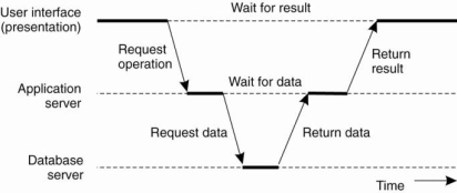
Figure 1.15 an example of server acting as client.
Above figure shows the three-tiered architecture n this programs that form part of the processing level reside on a separate server, but may additionally be partly distributed across the client and server machines. A typical example of where a three-tiered architecture is used is in transaction processing.
2. Decentralized Architecture
Multitiered client-server architectures are a direct consequence of dividing applications into a user-interface, processing components, and a data level.
In many business environments, distributed processing is equivalent to organizing a client-server application as a multitiered architecture. We refer to this type of distribution as vertical distribution. The characteristic feature ofvertical distribution is that it is achieved by placing logically different components on different machines.
A vertical distribution can help: functions are logically and physically split across multiple machines, where each machine is tailored to a specific group of functions.Vertical distribution is only one way of organizing client-server applications.
In modem architectures, it is often the distribution of the clients and the servers that counts, which we refer to as horizontal distribution. In this type of distribution, a client or server may be physically split up into logically equivalent parts, but each part is operating on its own share of the complete data set, thus balancing the load.
- Structured peer-to-peer Architecture
Modern system architectures that support horizontal distribution, known as peer-to-peer systems. In a structured peer-to-peer architecture, the overlay network is constructed using a deterministic procedure. The procedures are used to organize the process through Distributed Hash Table (DHT).
In a DHT -based system, data items are assigned a random key from a large identifier space, such as a 128-bit or 160-bit identifier. Likewise, nodes in the system are also assigned a random number from the same identifier space.
For example, in the Chord system (Stoica et al., 2003) the nodes are logically organized in a ring such that a data item with key k is mapped to the node with the smallest identifier id ~ k. This node is referred to as the successor of key k and denoted as succ(k), as shown in Fig. 1.16.
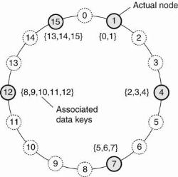
Figure 1.16 mapping of data items onto nodes in chord.
In this when a node wants to join the system, it starts with generating a random identifier id. Note that if the identifier space is large enough, then provided the random number generator is of good quality, the probability of generating an identifier that is already assigned to an actual node is close to zero. Then, the node can simply do a lookup on id, which will return the network address of succiid).
At that point, the joining node can simply contact succiid) and its predecessor and insert itself in the ring. Of course, this scheme requires that each node also stores information on its predecessor. Insertion also yields that each data item whose key is now associated with node id, is transferred from succiid).
b. Unstructured peer-to-peer Architecture
Unstructured peer-to-peer systems largely rely on randomized algorithms for constructing an overlay network. The main idea is that each node maintains a list of neighbors, but that this list is constructed in a more or less random way.
One of the goals of many unstructured peer-to-peer systems is to construct an overlay network that resembles a random graph. The basic model is that each node maintains a list of c neighbors, where, ideally, each of these neighbors represents a randomly chosen live node from the current set of nodes. The list of neighbors is also referred to as a partial view.
c. Topology Management of Overlay Networks
One key observation is that by carefully exchanging and selecting entries from partial views, it is possible to construct and maintain specific topologies of overlay networks. This topology management is achieved by adopting a two layered approach, as shown in Fig. 2-10.
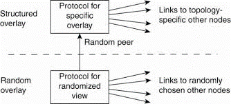
Fig 1.17 a two-layered approach for constructing and maintaining specific overlay topologies using techniques from unstructured peer-to-peer systems.
The lowest layer constitutes an unstructured peer-to-peer system in which nodes periodically exchange entries of their partial views with the aim to maintain an accurate random graph.
The lowest layer passes its partial view to the higher layer, where an additional selection of entries takes place. This then leads to a second list of neighbors corresponding to the desired topology.
d. Super-peers
Nodes such as those maintaining an index or acting as a broker are generally referred to as super-peers. As their name suggests, super-peers are often also organized in a peer-to-peer network, leading to a hierarchical organization as explained in Yang and Garcia-Molina.
A simple example of such an organization is shown in Fig. 1.20. In this organization, every regular peeris connected as a client to a super-peer. All communication from and to a regular peer proceeds through that peer's associated super-peer.
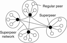
Fig 1.20 A hierarchical organization of nodes into a super-peer network.
In many cases, the client-super-peer relation is fixed: whenever a regular peer joins the network, it attaches to one of the super-peers and remains attached until it leaves the network. Obviously, it is expected that super-peers are long-lived processes with a high availability.
To compensate for potential unstable behavior of a super-peer, backup schemes can be deployed, such as pairing every super-peer with another one and requiring clients to attach to both.
3. Hybrid Architectures
Hybrid Architecture is combine some specific classes of distributed systems in which client-server solutions are combined with decentralized architectures.
- Edge-Server Systems
An important class of distributed systems that is organized according to a hybrid architecture is formed by edge-server systems. These systems are deployed on the Internet where servers are placed "at the edge" of the network.
This edge is formed by the boundary between enterprise networks and the actual Internet, for example, as provided by an Internet Service Provider (ISP).
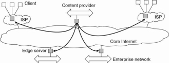
Fig 1.21 Viewing the Internet as consisting of a collection of edge servers.
End users, or clients in general, connect to the Internet by means of an edge server. The edge server's main purpose is to serve content, possibly after applying filtering and transcoding functions.
b. Collaborative Distributed Systems
Hybrid structures are notably deployed in collaborative distributed systems.The main issue in many of these systems to first get started, for which often a traditional client-server scheme is deployed. Once a node has joined the system, it can use a fully decentralized scheme for collaboration.
Consider the example of BitTorrent file sharing system. BitTorrent is a peer-to-peer file downloading system. Its principal working is shown in Fig. 1.22.
The basic idea is that when an end user is looking for a file, he downloads chunks of the file from other users until the downloaded chunks can be assembled together yielding the complete file. An important design goal was to ensure collaboration.
To download a file, a user needs to access a global directory, which is just one of a few well-known Web sites. Such a directory contains references to what are called .torrent files. A .torrent file contains the information that is needed to download a specific file.
In particular, it refers to what is known as a tracker, which is a server that is keeping an accurate account of active nodes that have (chunks) of the requested file.

Fig 1.22 the principal working of BitTorrent [adapted with permission from Pouwelse et al. (2004)].
Once the nodes have been identified from where chunks can be downloaded, the downloading node effectively becomes active.