UNIT 2
Processes, Thread, Process Scheduling
Process
A process is basically a program in execution. The execution of a process must progress in a sequential fashion.
A process is defined as an entity which represents the basic unit of work to be implemented in the system.
To put it in simple terms, we write our computer programs in a text file and when we execute this program, it becomes a process which performs all the tasks mentioned in the program.
When a program is loaded into the memory and it becomes a process, it can be divided into four sections ─ stack, heap, text and data. The following image shows a simplified layout of a process inside main memory −
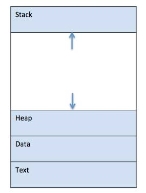
Fig 1 - a simplified layout of a process inside main memory
S.N. | Component & Description |
1 | Stack The process Stack contains the temporary data such as method/function parameters, return address and local variables. |
2 | Heap This is dynamically allocated memory to a process during its run time. |
3 | Text This includes the current activity represented by the value of Program Counter and the contents of the processor's registers. |
4 | Data This section contains the global and static variables. |
Program
A program is a piece of code which may be a single line or millions of lines. A computer program is usually written by a computer programmer in a programming language. For example, here is a simple program written in C programming language −
#include <stdio.h>
int main() {
printf("Hello, World! \n");
return 0;
}
A computer program is a collection of instructions that performs a specific task when executed by a computer. When we compare a program with a process, we can conclude that a process is a dynamic instance of a computer program.
A part of a computer program that performs a well-defined task is known as an algorithm. A collection of computer programs, libraries and related data are referred to as a software.
Process Life Cycle
When a process executes, it passes through different states. These stages may differ in different operating systems, and the names of these states are also not standardized.
In general, a process can have one of the following five states at a time.
S.N. | State & Description |
1 | Start This is the initial state when a process is first started/created. |
2 | Ready The process is waiting to be assigned to a processor. Ready processes are waiting to have the processor allocated to them by the operating system so that they can run. Process may come into this state after Start state or while running it by but interrupted by the scheduler to assign CPU to some other process. |
3 | Running Once the process has been assigned to a processor by the OS scheduler, the process state is set to running and the processor executes its instructions. |
4 | Waiting Process moves into the waiting state if it needs to wait for a resource, such as waiting for user input, or waiting for a file to become available. |
5 | Terminated or Exit Once the process finishes its execution, or it is terminated by the operating system, it is moved to the terminated state where it waits to be removed from main memory. |
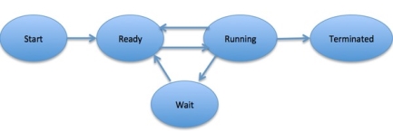
Fig 2 – Process state
Process Control Block (PCB)
A Process Control Block is a data structure maintained by the Operating System for every process. The PCB is identified by an integer process ID (PID). A PCB keeps all the information needed to keep track of a process as listed below in the table −
S.N. | Information & Description |
1 | Process State The current state of the process i.e., whether it is ready, running, waiting, or whatever. |
2 | Process privileges This is required to allow/disallow access to system resources. |
3 | Process ID Unique identification for each of the process in the operating system. |
4 | Pointer A pointer to parent process. |
5 | Program Counter Program Counter is a pointer to the address of the next instruction to be executed for this process. |
6 | CPU registers Various CPU registers where process need to be stored for execution for running state. |
7 | CPU Scheduling Information Process priority and other scheduling information which is required to schedule the process. |
8 | Memory management information This includes the information of page table, memory limits, Segment table depending on memory used by the operating system. |
9 | Accounting information This includes the amount of CPU used for process execution, time limits, execution ID etc. |
10 | IO status information This includes a list of I/O devices allocated to the process. |
The architecture of a PCB is completely dependent on Operating System and may contain different information in different operating systems. Here is a simplified diagram of a PCB −
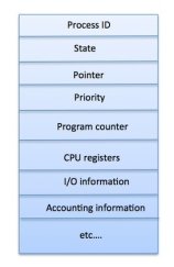
Fig 3 - PCB
The PCB is maintained for a process throughout its lifetime, and is deleted once the process terminates.
Key takeaway
A process is basically a program in execution. The execution of a process must progress in a sequential fashion.
A process is defined as an entity which represents the basic unit of work to be implemented in the system.
To put it in simple terms, we write our computer programs in a text file and when we execute this program, it becomes a process which performs all the tasks mentioned in the program.
When a program is loaded into the memory and it becomes a process, it can be divided into four sections ─ stack, heap, text and data. The following image shows a simplified layout of a process inside main memory −
What is a Process?
Process is that the execution of a program that performs the actions per that program. It will be outlined as associate degree execution unit wherever a program runs. The OS helps you to make, schedule, and terminates the processes that is employed by electronic equipment. A method created by the most method is termed a baby method.
Process operations will be simply controlled with the assistance of PCB(Process management Block). you'll be able to contemplate it because the brain of the method, that contains all the crucial info associated with process like method id, priority, state, electronic equipment registers, etc.
What is method Management?
Process management involves numerous tasks like creation, scheduling, termination of processes, and a dead lock. method could be a program that's beneath execution, that is a vital a part of modern in operation systems. The OS should assign resources that modify processes to share and exchange info. It conjointly protects the resources of every method from alternative ways and permits synchronization among processes.
It is the task of OS to manage all the running processes of the system. It handles operations by playing tasks like method planning and like resource allocation.
Process Architecture

Fig 4 -Process architecture Image
Here, is associate degree design diagram of the method
• Stack: The Stack stores temporary knowledge like perform parameters, returns addresses, and native variables.
• Heap Allocates memory, which can be processed throughout its run time.
• Data: It contains the variable.
• Text: Text Section includes the present activity, that is described by the worth of the Program Counter.
Process management Blocks
The PCB could be a full sort of method management Block. it's an information structure that's maintained by the software package for each method. The PCB ought to be known by associate degree whole number method ID (PID). It helps you to store all the knowledge needed to stay track of all the running processes.
It is conjointly in command of storing the contents of processor registers. These area unit saved once the method moves from the running state then returns back thereto. the knowledge is quickly updated within the PCB by the OS as presently because the method makes the state transition.
Process States
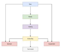
Fig 5 - Process States Diagram
A method state could be a condition of the method at a particular instant of your time. It conjointly defines the present position of the method.
There are a unit principally seven stages of a method that are:
• New: The new method is made once a particular program calls from secondary memory/ disc to primary memory/ RAM a
• Ready: in a very prepared state, the method ought to be loaded into the first memory, that is prepared for execution.
• Waiting: the method is expecting the allocation of electronic equipment time and alternative resources for execution.
• Executing: the method is associate degree execution state.
• Blocked: it's a interval once a method is expecting an occasion like I/O operations to finish.
• Suspended: Suspended state defines the time once a method {is prepared|is prepared} for execution however has not been placed within the ready queue by OS.
• Terminated: Terminated state specifies the time once a method is terminated
After finishing each step, all the resources area unit utilized by a method, and memory becomes free.
Process management Block(PCB)
Every method is described within the software package by a method management block, that is additionally referred to as a task management block.
Here, area unit necessary parts of PCB
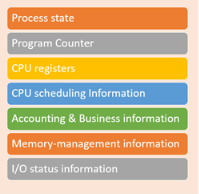
Fig 6 - Process Control Block (PCB)
• Process state: A method will be new, ready, running, waiting, etc.
• Program counter: The program counter allows you to grasp the address of future instruction, that ought to be dead for that method.
• CPU registers: This part includes accumulators, index and general registers, and knowledge of condition code.
• CPU planning information: This part includes a method priority, pointers for planning queues, and numerous alternative planning parameters.
• Accounting and business information: It includes the number of electronic equipment and time utilities like real time used, job or method numbers, etc.
• Memory-management info: This information includes the worth of the bottom and limit registers, the page, or section tables. this relies on the memory system, that is employed by the software package.
• I/O standing information: This block includes an inventory of open files, the list of I/O devices that area unit allotted to the method, etc.
Summary:
• A method is outlined because the execution of a program that performs the actions per that program.
• Process management involves numerous tasks like creation, scheduling, termination of processes, and a dead lock.
• The necessary components of method design area unit 1)Stack 2) Heap 3) knowledge, and 4) Text
• The PCB could be a full sort of method management Block. it's an information structure that's maintained by the software package for each method
• A method state could be a condition of the method at a particular instant of your time.
• Every method is described within the software package by a method management block, that is additionally referred to as a task management block.
Key takeaway
Process is the execution of a program that performs the actions specified in that program. It can be defined as an execution unit where a program runs. The OS helps you to create, schedule, and terminates the processes which is used by CPU. A process created by the main process is called a child process.
Process operations can be easily controlled with the help of PCB(Process Control Block). You can consider it as the brain of the process, which contains all the crucial information related to processing like process id, priority, state, CPU registers, etc.
Process States
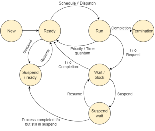
Fig 7 - State Diagram
The method, from its creation to completion, passes through varied states. The minimum range of states is 5.
The names of the states don't seem to be standardized though the method could also be in one amongst the subsequent states throughout execution.
1. New
A program that goes to be picked up by the OS into the most memory is termed a replacement method.
2. Ready
Whenever a method is made, it directly enters within the prepared state, in which, it waits for the electronic equipment to be allotted. The OS picks the new processes from the secondary memory and place all of them within the main memory.
The processes that are prepared for the execution and reside within the main memory are known as prepared state processes. There are often several processes gift within the prepared state.
3. Running
One of the processes from the prepared state are going to be chosen by the OS relying upon the programing formula. Hence, if we've got only 1 electronic equipment in our system, the quantity of running processes for a specific time can invariably be one. If we've got n processors within the system then we will have n processes running at the same time.
4. Block or wait
From the Running state, a method will create the transition to the block or wait state relying upon the programing formula or the intrinsic behavior of the method.
When a method waits for an exact resource to be allotted or for the input from the user then the OS move this method to the block or wait state and assigns the electronic equipment to the opposite processes.
5. Completion or termination
When a method finishes its execution, it comes within the termination state. All the context of the method (Process management Block) will be deleted the method are going to be terminated by the software system.
6. Suspend prepared
A method within the prepared state, that is emotional to secondary memory from the most memory because of lack of the resources (mainly primary memory) is termed within the suspend prepared state.
If the most memory is full and a better priority method comes for the execution then the OS need to create the area for {the method|the method} within the main memory by throwing the lower priority process out into the secondary memory. The suspend prepared processes stay within the secondary memory till the most memory gets out there.
7. Suspend wait
Instead of removing the method from the prepared queue, it's higher to get rid of the blocked method that is anticipating some resources within the main memory. Since it's already anticipating some resource to induce out there therefore it's higher if it waits within the secondary memory and create space for the upper priority method. These processes complete their execution once the most memory gets out there and their wait is finished.
Operations on the method
1. Creation
Once the method is made, it'll be prepared and are available into the prepared queue (main memory) and can be prepared for the execution.
2. Scheduling
Out of the various processes gift within the prepared queue, the software system chooses one method and begin capital punishment it. choosing the method that is to be dead next, is understood as programing.
3. Execution
Once the method is regular for the execution, the processor starts capital punishment it. method might come back to the blocked or wait state throughout the execution then there in case the processor starts capital punishment the opposite processes.
4. Deletion/killing
Once the aim of the method gets over then the OS can kill the method. The Context of {the method|the method} (PCB) are going to be deleted and also the process gets terminated by the software system.
Key takeaway
The process, from its creation to completion, passes through various states. The minimum number of states is five.
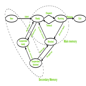
Fig 8 - States of a process
• New (Create) – during this step, the method is close to be created however not nevertheless created, it's the program that is gift in secondary memory which will be picked up by OS to make the method.
• Ready – New -> able to run. when the creation of a method, the method enters the prepared state i.e. the method is loaded into the most memory. the method here is prepared to run and is waiting to urge the central processor time for its execution. Processes that ar prepared for execution by the central processor ar maintained during a queue for prepared processes.
• Run – the method is chosen by central processor for execution and therefore the directions among the method ar dead by anyone of the on the market central processor cores.
• Blocked or wait – Whenever the method requests access to I/O or desires input from the user or desires access to a crucial region(the lock that is already acquired) it enters the blocked or wait state. the method continues to attend within the main memory and doesn't need central processor. Once the I/O operation is completed the method goes to the prepared state.
• Terminated or completed – method is killed also as PCB is deleted.
• Suspend prepared – method that was ab initio within the prepared state however were swapped out of main memory (refer storage topic) and placed onto auxiliary storage by hardware are aforesaid to be in suspend prepared state. the method can transition back to prepared state whenever the method is once more brought onto the most memory.
• Suspend wait or suspend blocked – kind of like suspend prepared however uses the method that was playing I/O operation and lack of main memory caused them to maneuver to secondary memory.
When work is finished it should move to suspend prepared.
CPU and IO sure Processes:
If {the method|the method} is intensive in terms of central processor operations then it's referred to as central processor sure process. Similarly, If {the method|the method} is intensive in terms of I/O operations then it's referred to as IO sure process.
Types of schedulers:
Multiprogramming – we've got several processes able to run. There are 2 styles of multiprogramming:
Degree of instruction execution –
The number of processes which will reside within the prepared state at most decides the degree of instruction execution, e.g., if the degree of programming = a hundred, this implies a hundred processes will reside within the prepared state at most.
Key takeaway
If the process is intensive in terms of CPU operations then it is called CPU bound process. Similarly, If the process is intensive in terms of I/O operations then it is called IO bound process.
Process Control Block is a data structure that contains information of the process related to it. The process control block is also known as a task control block, entry of the process table, etc.
It is very important for process management as the data structuring for processes is done in terms of the PCB. It also defines the current state of the operating system.
Structure of the Process Control Block
The process control stores many data items that are needed for efficient process management. Some of these data items are explained with the help of the given diagram −
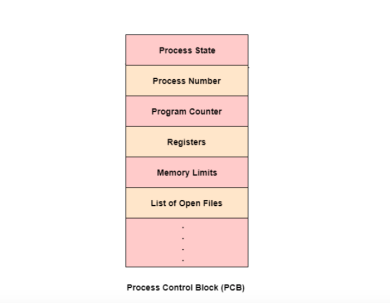
Fig 9 - PCB
The following are the data items −
Process State
This specifies the process state i.e. new, ready, running, waiting or terminated.
Process Number
This shows the number of the particular process.
Program Counter
This contains the address of the next instruction that needs to be executed in the process.
Registers
This specifies the registers that are used by the process. They may include accumulators, index registers, stack pointers, general purpose registers etc.
List of Open Files
These are the different files that are associated with the process
CPU Scheduling Information
The process priority, pointers to scheduling queues etc. is the CPU scheduling information that is contained in the PCB. This may also include any other scheduling parameters.
Memory Management Information
The memory management information includes the page tables or the segment tables depending on the memory system used. It also contains the value of the base registers, limit registers etc.
I/O Status Information
This information includes the list of I/O devices used by the process, the list of files etc.
Accounting information
The time limits, account numbers, amount of CPU used, process numbers etc. are all a part of the PCB accounting information.
Location of the Process Control Block
The process control block is kept in a memory area that is protected from the normal user access. This is done because it contains important process information. Some of the operating systems place the PCB at the beginning of the kernel stack for the process as it is a safe location.
Key takeaway
Process Control Block is a data structure that contains information of the process related to it. The process control block is also known as a task control block, entry of the process table, etc.
It is very important for process management as the data structuring for processes is done in terms of the PCB. It also defines the current state of the operating system.
The Context switching is a technique or method used by the operating system to switch a process from one state to another to execute its function using CPUs in the system. When switching perform in the system, it stores the old running process's status in the form of registers and assigns the CPU to a new process to execute its tasks. While a new process is running in the system, the previous process must wait in a ready queue. The execution of the old process starts at that point where another process stopped it. It defines the characteristics of a multitasking operating system in which multiple processes shared the same CPU to perform multiple tasks without the need for additional processors in the system.
The need for Context switching
A context switching helps to share a single CPU across all processes to complete its execution and store the system's tasks status. When the process reloads in the system, the execution of the process starts at the same point where there is conflicting.
Following are the reasons that describe the need for context switching in the Operating system.
Example of Context Switching
Suppose that multiple processes are stored in a Process Control Block (PCB). One process is running state to execute its task with the use of CPUs. As the process is running, another process arrives in the ready queue, which has a high priority of completing its task using CPU. Here we used context switching that switches the current process with the new process requiring the CPU to finish its tasks. While switching the process, a context switch saves the status of the old process in registers. When the process reloads into the CPU, it starts the execution of the process when the new process stops the old process. If we do not save the state of the process, we have to start its execution at the initial level. In this way, context switching helps the operating system to switch between the processes, store or reload the process when it requires executing its tasks.
Context switching triggers
Following are the three types of context switching triggers as follows.
Interrupts: A CPU requests for the data to read from a disk, and if there are any interrupts, the context switching automatic switches a part of the hardware that requires less time to handle the interrupts.
Multitasking: A context switching is the characteristic of multitasking that allows the process to be switched from the CPU so that another process can be run. When switching the process, the old state is saved to resume the process's execution at the same point in the system.
Kernel/User Switch: It is used in the operating systems when switching between the user mode, and the kernel/user mode is performed.
What is the PCB?
A PCB (Process Control Block) is a data structure used in the operating system to store all data related information to the process. For example, when a process is created in the operating system, updated information of the process, switching information of the process, terminated process in the PCB.
Steps for Context Switching
There are several steps involves in context switching of the processes. The following diagram represents the context switching of two processes, P1 to P2, when an interrupt, I/O needs, or priority-based process occurs in the ready queue of PCB.
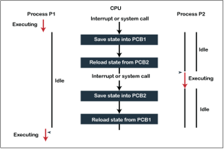
Fig 10 - the context switching of two processes
As we can see in the diagram, initially, the P1 process is running on the CPU to execute its task, and at the same time, another process, P2, is in the ready state. If an error or interruption has occurred or the process requires input/output, the P1 process switches its state from running to the waiting state. Before changing the state of the process P1, context switching saves the context of the process P1 in the form of registers and the program counter to the PCB1. After that, it loads the state of the P2 process from the ready state of the PCB2 to the running state.
The following steps are taken when switching Process P1 to Process 2:
Similarly, process P2 is switched off from the CPU so that the process P1 can resume execution. P1 process is reloaded from PCB1 to the running state to resume its task at the same point. Otherwise, the information is lost, and when the process is executed again, it starts execution at the initial level.
Key takeaway
The Context switching is a technique or method used by the operating system to switch a process from one state to another to execute its function using CPUs in the system. When switching perform in the system, it stores the old running process's status in the form of registers and assigns the CPU to a new process to execute its tasks. While a new process is running in the system, the previous process must wait in a ready queue. The execution of the old process starts at that point where another process stopped it. It defines the characteristics of a multitasking operating system in which multiple processes shared the same CPU to perform multiple tasks without the need for additional processors in the system.
There is the way of thread execution within the method of any software. with the exception of this, there may be quite one thread within a method. Thread is usually cited as a light-weight method.
The process may be reduction into such a big amount of threads. for instance, in an exceedingly browser, several tabs may be viewed as threads. MS Word uses several threads - data format text from one thread, process input from another thread, etc.
Types of Threads
In the software, there square measure 2 sorts of threads.
User-level thread
The software doesn't acknowledge the user-level thread. User threads may be simply enforced and it's enforced by the user. If a user performs a user-level thread obstruction operation, the complete method is blocked. The kernel level thread doesn't unskilled person regarding the user level thread. The kernel-level thread manages user-level threads as if they're single-threaded processes? Examples: Java thread, POSIX threads, etc.
Advantages of User-level threads
Disadvantages of User-level threads
Kernel level thread
The kernel thread acknowledges the software. There square measure a thread management block and method management block within the system for every thread and method within the kernel-level thread. The kernel-level thread is enforced by the software. The kernel is aware of regarding all the threads and manages them. The kernel-level thread offers a supervisor call instruction to form and manage the threads from user-space. The implementation of kernel threads is troublesome than the user thread. Context switch time is longer within the kernel thread. If a kernel thread performs a obstruction operation, the Banky thread execution will continue. Example: Window Solaris.
Advantages of Kernel-level threads
Disadvantages of Kernel-level threads
Components of Threads
Any thread has the subsequent parts.
Benefits of Threads
• Enhanced outturn of the system: once the method is split into several threads, and every thread is treated as employment, the quantity of jobs worn out the unit time will increase. that's why the outturn of the system additionally will increase.
• Effective Utilization of digital computer system: after you have quite one thread in one method, you'll be able to schedule quite one thread in additional than one processor.
• Faster context switch: The context shift amount between threads is a smaller amount than the method context shift. the method context switch suggests that additional overhead for the hardware.
• Responsiveness: once the method is split into many threads, and once a thread completes its execution, that method may be suffered as before long as doable.
• Communication: Multiple-thread communication is easy as a result of the threads share an equivalent address house, whereas in method, we have a tendency to adopt simply some exclusive communication methods for communication between 2 processes.
• Resource sharing: Resources may be shared between all threads at intervals a method, like code, data, and files. Note: The stack and register can't be shared between threads. There square measure a stack and register for every thread.
Thread State Diagram
Appearing on your screen may be a thread state diagram. Let's take a more in-depth explore the various states showing on the diagram.
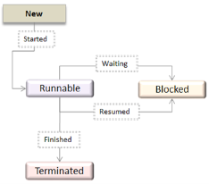
Fig 11 - OS Thread State Diagram
|
|
A thread is within the new state once it's been created. It does not take any hardware resources till it's really running. Now, the method is taking on hardware resources as a result of it's able to run. However, it's in an exceedingly runnable state as a result of it might be looking forward to another thread to run and then it's to attend for its flip.
A thread that isn't allowed to continue remains in an exceedingly blocked state. parenthetically that a thread is looking forward to input/output (I/O), however it ne'er gets those resources, therefore it'll stay in an exceedingly blocked state. the great news is that a blocked thread will not use hardware resources. The thread is not stopped forever. for instance, if you permit emergency vehicles to pass, it doesn't mean that you just square measure forever barred from your final destination. Similarly, those threads (emergency vehicles) that have the next priority square measure processed prior to you. If a thread becomes blocked, another thread moves to the front of the road. However, this is often accomplished is roofed within the next section regarding programming and context shift.
Finally, a thread is terminated if it finishes a task with success or abnormally. At this time, no hardware resources square measure used.
Multithreading Models
Some operating system provides a combined user level thread and Kernel level thread facility. Solaris is a good example of this combined approach. In a combined system, multiple threads within the same application can run in parallel on multiple processors and a blocking system call need not block the entire process. Multithreading models are three types
Many to Many Model
The many-to-many model multiplexes any number of user threads onto an equal or smaller number of kernel threads.
The following diagram shows the many-to-many threading model where 6 user level threads are multiplexing with 6 kernel level threads. In this model, developers can create as many user threads as necessary and the corresponding Kernel threads can run in parallel on a multiprocessor machine. This model provides the best accuracy on concurrency and when a thread performs a blocking system call, the kernel can schedule another thread for execution.
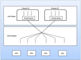
Fig 12 - the best accuracy on concurrency
Many to One Model
Many-to-one model maps many user level threads to one Kernel-level thread. Thread management is done in user space by the thread library. When thread makes a blocking system call, the entire process will be blocked. Only one thread can access the Kernel at a time, so multiple threads are unable to run in parallel on multiprocessors.
If the user-level thread libraries are implemented in the operating system in such a way that the system does not support them, then the Kernel threads use the many-to-one relationship modes.
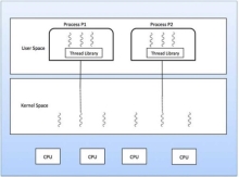
Fig 13 – Many to one model
One to One Model
There is one-to-one relationship of user-level thread to the kernel-level thread. This model provides more concurrency than the many-to-one model. It also allows another thread to run when a thread makes a blocking system call. It supports multiple threads to execute in parallel on microprocessors.
Disadvantage of this model is that creating user thread requires the corresponding Kernel thread. OS/2, windows NT and windows 2000 use one to one relationship model.
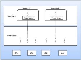
Fig 14 – one to one model
Difference between User-Level & Kernel-Level Thread
S.N. | User-Level Threads | Kernel-Level Thread |
1 | User-level threads are faster to create and manage. | Kernel-level threads are slower to create and manage. |
2 | Implementation is by a thread library at the user level. | Operating system supports creation of Kernel threads. |
3 | User-level thread is generic and can run on any operating system. | Kernel-level thread is specific to the operating system. |
4 | Multi-threaded applications cannot take advantage of multiprocessing. | Kernel routines themselves can be multithreaded. |
Key takeaway
There is a way of thread execution inside the process of any operating system. Apart from this, there can be more than one thread inside a process. Thread is often referred to as a lightweight process.
The process can be split down into so many threads. For example, in a browser, many tabs can be viewed as threads. MS Word uses many threads - formatting text from one thread, processing input from another thread, etc.
Definition
The process scheduling is the activity of the process manager that handles the removal of the running process from the CPU and the selection of another process on the basis of a particular strategy.
Process scheduling is an essential part of a Multiprogramming operating systems. Such operating systems allow more than one process to be loaded into the executable memory at a time and the loaded process shares the CPU using time multiplexing.
Process Scheduling Queues
The OS maintains all PCBs in Process Scheduling Queues. The OS maintains a separate queue for each of the process states and PCBs of all processes in the same execution state are placed in the same queue. When the state of a process is changed, its PCB is unlinked from its current queue and moved to its new state queue.
The Operating System maintains the following important process scheduling queues −
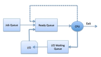
Fig 15 – Process state
The OS can use different policies to manage each queue (FIFO, Round Robin, Priority, etc.). The OS scheduler determines how to move processes between the ready and run queues which can only have one entry per processor core on the system; in the above diagram, it has been merged with the CPU.
Two-State Process Model
Two-state process model refers to running and non-running states which are described below −
S.N. | State & Description |
1 | Running When a new process is created, it enters into the system as in the running state. |
2 | Not Running Processes that are not running are kept in queue, waiting for their turn to execute. Each entry in the queue is a pointer to a particular process. Queue is implemented by using linked list. Use of dispatcher is as follows. When a process is interrupted, that process is transferred in the waiting queue. If the process has completed or aborted, the process is discarded. In either case, the dispatcher then selects a process from the queue to execute. |
Schedulers
Schedulers are special system software which handle process scheduling in various ways. Their main task is to select the jobs to be submitted into the system and to decide which process to run. Schedulers are of three types −
Long Term Scheduler
It is also called a job scheduler. A long-term scheduler determines which programs are admitted to the system for processing. It selects processes from the queue and loads them into memory for execution. Process loads into the memory for CPU scheduling.
The primary objective of the job scheduler is to provide a balanced mix of jobs, such as I/O bound and processor bound. It also controls the degree of multiprogramming. If the degree of multiprogramming is stable, then the average rate of process creation must be equal to the average departure rate of processes leaving the system.
On some systems, the long-term scheduler may not be available or minimal. Time-sharing operating systems have no long-term scheduler. When a process changes the state from new to ready, then there is use of long-term scheduler.
Short Term Scheduler
It is also called as CPU scheduler. Its main objective is to increase system performance in accordance with the chosen set of criteria. It is the change of ready state to running state of the process. CPU scheduler selects a process among the processes that are ready to execute and allocates CPU to one of them.
Short-term schedulers, also known as dispatchers, make the decision of which process to execute next. Short-term schedulers are faster than long-term schedulers.
Medium Term Scheduler
Medium-term scheduling is a part of swapping. It removes the processes from the memory. It reduces the degree of multiprogramming. The medium-term scheduler is in-charge of handling the swapped out-processes.
A running process may become suspended if it makes an I/O request. A suspended process cannot make any progress towards completion. In this condition, to remove the process from memory and make space for other processes, the suspended process is moved to the secondary storage. This process is called swapping, and the process is said to be swapped out or rolled out. Swapping may be necessary to improve the process mix.
Comparison among Scheduler
S.N. | Long-Term Scheduler | Short-Term Scheduler | Medium-Term Scheduler |
1 | It is a job scheduler | It is a CPU scheduler | It is a process swapping scheduler. |
2 | Speed is lesser than short term scheduler | Speed is fastest among other two | Speed is in between both short- and long-term scheduler. |
3 | It controls the degree of multiprogramming | It provides lesser control over degree of multiprogramming | It reduces the degree of multiprogramming. |
4 | It is almost absent or minimal in time sharing system | It is also minimal in time sharing system | It is a part of Time-sharing systems. |
5 | It selects processes from pool and loads them into memory for execution | It selects those processes which are ready to execute | It can re-introduce the process into memory and execution can be continued. |
Context Switch
A context switch is the mechanism to store and restore the state or context of a CPU in Process Control block so that a process execution can be resumed from the same point at a later time. Using this technique, a context switcher enables multiple processes to share a single CPU. Context switching is an essential part of a multitasking operating system features.
When the scheduler switches the CPU from executing one process to execute another, the state from the current running process is stored into the process control block. After this, the state for the process to run next is loaded from its own PCB and used to set the PC, registers, etc. At that point, the second process can start executing.
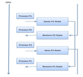
Fig 16 – Process state
Context switches are computationally intensive since register and memory state must be saved and restored. To avoid the amount of context switching time, some hardware systems employ two or more sets of processor registers. When the process is switched, the following information is stored for later use.
Key takeaway
The process scheduling is the activity of the process manager that handles the removal of the running process from the CPU and the selection of another process on the basis of a particular strategy.
Process scheduling is an essential part of a Multiprogramming operating systems. Such operating systems allow more than one process to be loaded into the executable memory at a time and the loaded process shares the CPU using time multiplexing.
Process programming handles the choice of a method for the methodor on the idea of a programming algorithmic program and conjointly the removal of a process from the processor. it's a crucial a part of execution software.
There square measure several programming queues that square measure employed in method programming. once the processes enter the system, they're place into the task queue. The processes that square measure able to execute within the main memory square measure unbroken within the prepared queue. The processes that square measure watching for the I/O device square measure unbroken within the I/O device queue.
The different schedulers that square measure used for method programming square measure square measure
Long Term hardware
The job hardware or long hardware selects processes from the storage pool within the secondary memory and masses them into the prepared queue within the main memory for execution.
The long hardware controls the degree of execution. It should choose a careful mixture of I/O sure and mainframe sure processes to yield optimum system turnout. If it selects too several mainframe sure processes then the I/O devices square measure idle and if it selects too several I/O sure processes then the processor has nothing to try to.
The job of the long hardware is incredibly vital and directly affects the system for an extended time.
Short Term hardware
The short hardware selects one in every of the processes from the prepared queue and schedules them for execution. A programming algorithmic program is employed to make your mind up that method are regular for execution next.
The short hardware executes rather more oftentimes than the long hardware as a method could execute just for many milliseconds.
The choices of the short-term hardware square measure important. If it selects a method with an extended burst time, then all the processes afterward can ought to expect an extended time within the prepared queue. this is often referred to as starvation and it should happen if a wrong call is formed by the short hardware.
A diagram that demonstrates long and short schedulers is given as follows −
Medium Term hardware
The medium-term hardware swaps out a method from main memory. It will once more swap within the method later from the purpose it stopped death penalty. this could even be known as as suspending and resuming the method.
This is useful in reducing the degree of execution. Swapping is additionally helpful to enhance the combo of I/O sure and mainframe sure processes within the memory.
A diagram that demonstrates medium-term scheduling is given as follows −
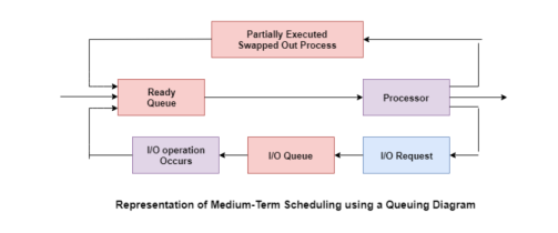
Fig 17 – Medium term scheduling using a queue
Key takeaway
Process Scheduling handles the selection of a process for the processor on the basis of a scheduling algorithm and also the removal of a process from the processor. It is an important part of multiprogramming operating system.
There are many scheduling queues that are used in process scheduling. When the processes enter the system, they are put into the job queue. The processes that are ready to execute in the main memory are kept in the ready queue. The processes that are waiting for the I/O device are kept in the I/O device queue.
Different processor programing formulas have totally different properties and also the alternative of a specific algorithm depends on the assorted factors. several criteria are advised for scrutiny processor programing algorithms.
The criteria embrace the following:
The main objective of any processor programing formula is to stay the processor as busy as doable. in theory, processor use will vary from zero to a hundred however in a very period of time system, it varies from forty to ninety p.c. looking on the load upon the system.
2. outturn –
A live of the work done by processor is that the variety of processes being dead and completed per unit time. this is often referred to as outturn. The outturn might vary relying upon the length or length of processes.
3. turnaround –
For a specific method, a crucial criterion is however long it takes to execute that method. The time progress from the time of submission of a method to the time of completion is understood because the turnaround. Turn-around time is that the addition of times spent waiting to urge into memory, waiting in prepared queue, death penalty in processor, and looking forward to I/O.
4. Waiting time –
A programing formula doesn't have an effect on the time needed to complete the method once it starts execution. It solely affects the waiting time of a method i.e. time spent by a method waiting within the prepared queue.
5. reaction time –
In AN interactive system, turn-around time isn't the simplest criteria. A method might manufacture some output fairly early and continue computing new results whereas previous results square measure being output to the user. Therefore, another criterion is that the time taken from submission of the method of request till the primary response is created. This live is named reaction time.
Key takeaway
Different CPU scheduling algorithms have different properties and the choice of a particular algorithm depends on the various factors. Many criteria have been suggested for comparing CPU scheduling algorithms.
A Process Scheduler schedules different processes to be assigned to the CPU based on particular scheduling algorithms. There are six popular process scheduling algorithms which we are going to discuss in this chapter −
These algorithms are either non-pre-emptive or pre-emptive. Non-pre-emptive algorithms are designed so that once a process enters the running state, it cannot be pre-empted until it completes its allotted time, whereas the pre-emptive scheduling is based on priority where a scheduler may pre-empt a low priority running process anytime when a high priority process enters into a ready state.
First Come First Serve (FCFS)
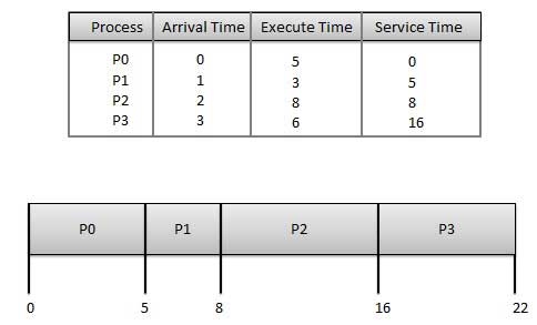
Wait time of each process is as follows −
Process | Wait Time: Service Time - Arrival Time |
P0 | 0 - 0 = 0 |
P1 | 5 - 1 = 4 |
P2 | 8 - 2 = 6 |
P3 | 16 - 3 = 13 |
Average Wait Time: (0+4+6+13) / 4 = 5.75
Shortest Job Next (SJN)
Given: Table of processes, and their Arrival time, Execution time
Process | Arrival Time | Execution Time | Service Time |
P0 | 0 | 5 | 0 |
P1 | 1 | 3 | 5 |
P2 | 2 | 8 | 14 |
P3 | 3 | 6 | 8 |

Waiting time of each process is as follows −
Process | Waiting Time |
P0 | 0 - 0 = 0 |
P1 | 5 - 1 = 4 |
P2 | 14 - 2 = 12 |
P3 | 8 - 3 = 5 |
Average Wait Time: (0 + 4 + 12 + 5)/4 = 21 / 4 = 5.25
Priority Based Scheduling
Given: Table of processes, and their Arrival time, Execution time, and priority. Here we are considering 1 is the lowest priority.
Process | Arrival Time | Execution Time | Priority | Service Time |
P0 | 0 | 5 | 1 | 0 |
P1 | 1 | 3 | 2 | 11 |
P2 | 2 | 8 | 1 | 14 |
P3 | 3 | 6 | 3 | 5 |
Waiting time of each process is as follows −
Process | Waiting Time |
P0 | 0 - 0 = 0 |
P1 | 11 - 1 = 10 |
P2 | 14 - 2 = 12 |
P3 | 5 - 3 = 2 |
Average Wait Time: (0 + 10 + 12 + 2)/4 = 24 / 4 = 6
Shortest Remaining Time
Round Robin Scheduling
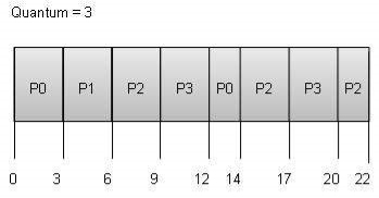
Wait time of each process is as follows −
Process | Wait Time: Service Time - Arrival Time |
P0 | (0 - 0) + (12 - 3) = 9 |
P1 | (3 - 1) = 2 |
P2 | (6 - 2) + (14 - 9) + (20 - 17) = 12 |
P3 | (9 - 3) + (17 - 12) = 11 |
Average Wait Time: (9+2+12+11) / 4 = 8.5
Multiple-Level Queues Scheduling
Multiple-level queues are not an independent scheduling algorithm. They make use of other existing algorithms to group and schedule jobs with common characteristics.
For example, CPU-bound jobs can be scheduled in one queue and all I/O-bound jobs in another queue. The Process Scheduler then alternately selects jobs from each queue and assigns them to the CPU based on the algorithm assigned to the queue.
Key takeaway
A Process Scheduler schedules different processes to be assigned to the CPU based on particular scheduling algorithms. There are six popular process scheduling algorithms which we are going to discuss in this chapter −
Multiple-Processor programing in package
In multiple-processor programing multiple CPU’s square measure offered and therefore Load Sharing becomes attainable. but multiple processor programing is additional complicated as compared to single processor programing. In multiple processors programing their square measure cases once the processors square measure identical i.e. undiversified, in terms of their practicality, we are able to use any methodor offered to run any process within the queue.
Approaches to Multiple-Processor programing –
One approach is once all the programing selections and I/O process square measure handled by one processor that is named the Master Server and therefore the different processors executes solely the user code. this can be straightforward and reduces the requirement of information sharing. this whole state of affairs is named uneven parallel processing.
A second approach uses regular parallel processing wherever every processor is self programing. All processes could also be in an exceedingly common prepared queue or every processor might have its own non-public queue for prepared processes. The programing income additional by having the computer hardware for every methodor examine the prepared queue and choose a process to execute.
Processor Affinity –
Processor Affinity suggests that a process has AN affinity for the processor on that it's presently running.
When a method runs on a particular processor their square measure sure effects on the cache memory. the information last accessed by {the method|the method} populate the cache for the methodor and as a result serial access by the process square measure usually happy within the cache memory. currently if the method migrates to a different processor, the contents of the cache memory should be nullified for the primary processor and therefore the cache for the second processor should be repopulated. attributable to the high value of disconfirming and repopulating caches, most of the SMP (symmetric multiprocessing) systems try and avoid migration of methodes from one processor to a different and check out to stay a process running on an equivalent processor. this can be referred to as PROCESSOR AFFINITY.
There square measure 2 sorts of processor affinity:
Load equalisation –
Load equalisation is that the phenomena that keeps the employment equally distributed across all processors in AN SMP system. Load equalisation is critical solely on systems wherever every methodor has its own non-public queue of process that square measure eligible to execute. Load equalisation makes no sense as a result of once a methodor becomes idle it forthwith extracts a runnable process from the common run queue. On SMP(symmetric multiprocessing), it's vital to stay the employment balanced among all processors to totally utilize the advantages of getting quite one processor else one or additional processor can sit idle whereas different processors have high workloads together with lists of processors awaiting the hardware.
There square measure 2 general approaches to load equalisation:
Multicore Processors –
In multicore processors multiple processor cores square measure places on an equivalent physical chip. every core includes a register set to take care of its subject state and so seems to the package as a separate physical processor. SMP systems that use multicore processors square measure quicker and consume less power than systems within which every processor has its own physical chip.
However multicore processors might complicate the programing issues. once processor accesses memory then it spends a major quantity of your time expecting the information to become offered. this case is named MEMORY STALL. It happens for numerous reasons like cache miss, that is accessing the information that's not within the cache memory. In such cases the processor will pay upto one-half of its time expecting information to become offered from the memory. to resolve this downside recent hardware styles have enforced multithreaded processor cores within which 2 or additional hardware threads square measure assigned to every core. So, if one thread stalls whereas expecting the memory, core will switch to a different thread.
There square measure 2 ways in which to multithread a processor:
Virtualization and Threading –
In this kind of multiple-processor planning even one C.P.U. system acts sort of a multiple-processor system. in an exceedingly system with Virtualization, the virtualization presents one or additional virtual C.P.U. to every of virtual machines running on the system so schedules the utilization of physical C.P.U. among the virtual machines. Most virtualized environments have one host OS and lots of guest in operation systems. The host OS creates and manages the virtual machines. every virtual machine encompasses a guest OS put in and applications run among that guest. Each guest OS could also be appointed for specific use cases, applications or users together with sharing or maybe real-time processing. Any guest operating-system planning algorithmic program that assumes a definite quantity of progress in an exceedingly given quantity of your time are going to be negatively compact by the virtualization. A sharing OS tries to allot a hundred milliseconds to every time slice to relinquish users an affordable reaction time. A given a hundred-time unit time slice might take rather more than a hundred milliseconds of virtual C.P.U. time. counting on however busy the system is, the time slice might take a second or additional which ends terribly} very poor reaction time for users logged into that virtual machine. cyber web result of such planning layering is that individual virtualized in operation systems receive solely some of the on the market C.P.U. cycles, albeit they believe they're receiving all cycles which they're planning all of these cycles. Commonly, the time-of-day clocks in virtual machines ar incorrect as a result of timers take now not to trigger than they might on dedicated CPU’s.
Virtualizations will therefore undo the great scheduling-algorithm efforts of the in-operation systems among virtual machines.
Scheduling in Real Time Systems
Real-time systems are systems that carry period of time tasks. These tasks got to be performed at once with a definite degree of urgency. specifically, these tasks are associated with management of bound events (or) reacting to them. period of time tasks will be classified as onerous period of time tasks and soft period of time tasks.
A hard period of time task should be performed at a mere time that might otherwise cause immense losses. In soft period of time tasks, a mere point will be uncomprehensible. {this is|this is often|this will be} as a result of the task will be rescheduled (or) can be completed once the required time,
In period of time systems, the hardware is taken into account because the most vital part that is often a short task hardware. the most focus of this hardware is to cut back the reaction time related to every of the associated processes rather than handling the point.
If a preventive hardware is employed, the period of time task has to wait till its corresponding tasks time slice completes. within the case of a non-pre-emptive hardware, even though the best priority is allotted to the task, it has to wait till the completion of the present task. This task will be slow (or) of the lower priority and might cause an extended wait.
A better approach is intended by combining each preventive and non-pre-emptive planning. this will be done by introducing time-based interrupts in priority primarily based systems which suggests the presently running method is interrupted on a time-based interval and if the next priority method is gift in an exceedingly prepared queue, it's dead by pre-empting the present method.
Based on schedulability, implementation (static or dynamic), and also the result (self or dependent) of research, the planning algorithmic program ar classified as follows.
These algorithms sometimes perform a static analysis related to planning and capture the schedules that ar advantageous. This helps in providing a schedule that may denote a task with that the execution should be started at run time.
2. Static priority-driven preventive approaches:
Similar to the primary approach, this kind of algorithms conjointly uses static analysis of planning. The distinction is that rather than choosing a specific schedule, it provides a helpful method of assignment priorities among varied tasks in preventive planning.
3. Dynamic planning-based approaches:
Here, the possible schedules are known dynamically (at run time). It carries a definite mounted quantity and a method is dead if and provided that satisfies the time constraint.
4. Dynamic best effort approaches:
These sorts of approaches contemplate deadlines rather than possible schedules. Thus, the task is aborted if its point is reached. This approach is employed wide is most of the period of time systems.
Key takeaway
In multiple-processor scheduling multiple CPU’s are available and hence Load Sharing becomes possible. However multiple processor scheduling is more complex as compared to single processor scheduling. In multiple processor scheduling there are cases when the processors are identical i.e. HOMOGENEOUS, in terms of their functionality, we can use any processor available to run any process in the queue.
References