UNIT 6
File Management, Disk Management, I/O Hardware
What is File System?
A file is a collection of correlated information which is recorded on secondary or non-volatile storage like magnetic disks, optical disks, and tapes. It is a method of data collection that is used as a medium for giving input and receiving output from that program.
In general, a file is a sequence of bits, bytes, or records whose meaning is defined by the file creator and user. Every File has a logical location where they are located for storage and retrieval.
Objective of File management System
Here are the main objectives of the file management system:
Here, are important properties of a file system:
A File Structure needs to be predefined format in such a way that an operating system understands. It has an exclusively defined structure, which is based on its type.
Three types of files structure in OS:
A file has a name and data. Moreover, it also stores meta information like file creation date and time, current size, last modified date, etc. All this information is called the attributes of a file system.
Here, are some important File attributes used in OS:
It refers to the ability of the operating system to differentiate various types of files like text files, binary, and source files. However, Operating systems like MS_DOS and UNIX has the following type of files:
It is a hardware file that reads or writes data character by character, like mouse, printer, and more.
Commonly used terms in File systems
This element stores a single value, which can be static or variable length.
Collection of related data is called a database. Relationships among elements of data are explicit.
Files is the collection of similar record which is treated as a single entity.
A Record type is a complex data type that allows the programmer to create a new data type with the desired column structure. Its groups one or more columns to form a new data type. These columns will have their own names and data type.
File access is a process that determines the way that files are accessed and read into memory. Generally, a single access method is always supported by operating systems. Though there are some operating system which also supports multiple access methods.
Three file access methods are:
In this type of file access method, records are accessed in a certain pre-defined sequence. In the sequential access method, information stored in the file is also processed one by one. Most compilers access files using this access method.
The random access method is also called direct random access. This method allows accessing the record directly. Each record has its own address on which can be directly accessed for reading and writing.
This type of accessing method is based on simple sequential access. In this access method, an index is built for every file, with a direct pointer to different memory blocks. In this method, the Index is searched sequentially, and its pointer can access the file directly. Multiple levels of indexing can be used to offer greater efficiency in access. It also reduces the time needed to access a single record.
In the Operating system, files are always allocated disk spaces.
Three types of space allocation methods are:
In this method,
In this method,
In this method,
A single directory may or may not contain multiple files. It can also have sub-directories inside the main directory. Information about files is maintained by Directories. In Windows OS, it is called folders.
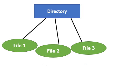
Fig 1 - Single Level Directory
Following is the information which is maintained in a directory:
File Type | Usual extension | Function |
Executable | exe, com, bin or none | ready-to-run machine- language program |
Object | obj, o | complied, machine language, not linked |
Source code | c. p, pas, 177, asm, a | source code in various languages |
Batch | bat, sh | Series of commands to be executed |
Text | txt, doc | textual data documents |
Word processor | doc,docs, tex, rrf, etc. | various word-processor formats |
Library | lib, h | libraries of routines |
Archive | arc, zip, tar | related files grouped into one file, sometimes compressed. |
- Linked Allocation
- Indexed Allocation
- Contiguous Allocation
Key takeaway
A file is a collection of correlated information which is recorded on secondary or non-volatile storage like magnetic disks, optical disks, and tapes. It is a method of data collection that is used as a medium for giving input and receiving output from that program.
In general, a file is a sequence of bits, bytes, or records whose meaning is defined by the file creator and user. Every File has a logical location where they are located for storage and retrieval.
There are various methods which can be used to allocate disk space to the files. Selection of an appropriate allocation method will significantly affect the performance and efficiency of the system. Allocation method provides a way in which the disk will be utilized and the files will be accessed.
There are following methods which can be used for allocation.
If the blocks are allocated to the file in such a way that all the logical blocks of the file get the contiguous physical block in the hard disk then such allocation scheme is known as contiguous allocation.
In the image shown below, there are three files in the directory. The starting block and the length of each file are mentioned in the table. We can check in the table that the contiguous blocks are assigned to each file as per its need.
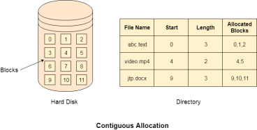
Fig 2 – Contiguous allocation
Linked List allocation solves all problems of contiguous allocation. In linked list allocation, each file is considered as the linked list of disk blocks. However, the disks blocks allocated to a particular file need not to be contiguous on the disk. Each disk block allocated to a file contains a pointer which points to the next disk block allocated to the same file.

Fig 3 – linked list allocation
Limitation in the existing technology causes the evolution of a new technology. Till now, we have seen various allocation methods; each of them was carrying several advantages and disadvantages.
File allocation table tries to solve as many problems as possible but leads to a drawback. The more the number of blocks, the more will be the size of FAT.
Therefore, we need to allocate more space to a file allocation table. Since, file allocation table needs to be cached therefore it is impossible to have as many space in cache. Here we need a new technology which can solve such problems.
Instead of maintaining a file allocation table of all the disk pointers, Indexed allocation scheme stores all the disk pointers in one of the blocks called as indexed block. Indexed block doesn't hold the file data, but it holds the pointers to all the disk blocks allocated to that particular file. Directory entry will only contain the index block address.
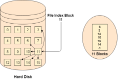
Fig 4 – Index allocation
Key takeaway
There are various methods which can be used to allocate disk space to the files. Selection of an appropriate allocation method will significantly affect the performance and efficiency of the system. Allocation method provides a way in which the disk will be utilized and the files will be accessed.
The system keeps tracks of the free disk blocks for allocating space to files when they are created. Also, to reuse the space released from deleting the files, free space management becomes crucial. The system maintains a free space list which keeps track of the disk blocks that are not allocated to some file or directory. The free space list can be implemented mainly as:
A Bitmap or Bit Vector is series or collection of bits where each bit corresponds to a disk block. The bit can take two values: 0 and 1: 0 indicates that the block is allocated and 1 indicates a free block.
The given instance of disk blocks on the disk in Figure 1 (where green blocks are allocated) can be represented by a bitmap of 16 bits as: 0000111000000110.
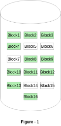
Fig 5 - Example
Advantages –
The block number can be calculated as:
(number of bits per word) *(number of 0-values words) + offset of bit first bit 1 in the non-zero word.
For the Figure-1, we scan the bitmap sequentially for the first non-zero word.
The first group of 8 bits (00001110) constitute a non-zero word since all bits are not 0. After the non-0 word is found, we look for the first 1 bit. This is the 5th bit of the non-zero word. So, offset = 5.
Therefore, the first free block number = 8*0+5 = 5.
2. Linked List –
In this approach, the free disk blocks are linked together i.e. a free block contains a pointer to the next free block. The block number of the very first disk block is stored at a separate location on disk and is also cached in memory.
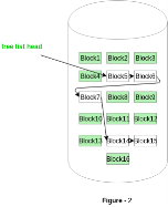
Fig 6 - example
In Figure-2, the free space list head points to Block 5 which points to Block 6, the next free block and so on. The last free block would contain a null pointer indicating the end of free list. A drawback of this method is the I/O required for free space list traversal.
3. Grouping –
This approach stores the address of the free blocks in the first free block. The first free block stores the address of some, say n free blocks. Out of these n blocks, the first n-1 blocks are actually free and the last block contains the address of next free n blocks. An advantage of this approach is that the addresses of a group of free disk blocks can be found easily.
4. Counting –
This approach stores the address of the first free disk block and a number n of free contiguous disk blocks that follow the first block.
Every entry in the list would contain:
For example, in Figure-1, the first entry of the free space list would be: ([Address of Block 5], 2), because 2 contiguous free blocks follow block 5.
Key takeaway
The system keeps tracks of the free disk blocks for allocating space to files when they are created. Also, to reuse the space released from deleting the files, free space management becomes crucial. The system maintains a free space list which keeps track of the disk blocks that are not allocated to some file or directory.
There is the number of algorithms by using which, the directories can be implemented. However, the selection of an appropriate directory implementation algorithm may significantly affect the performance of the system.
The directory implementation algorithms are classified according to the data structure they are using. There are mainly two algorithms which are used in these days.
In this algorithm, all the files in a directory are maintained as singly lined list. Each file contains the pointers to the data blocks which are assigned to it and the next file in the directory.
Characteristics

Fig 7 – linear list
To overcome the drawbacks of singly linked list implementation of directories, there is an alternative approach that is hash table. This approach suggests to use hash table along with the linked lists.
A key-value pair for each file in the directory gets generated and stored in the hash table. The key can be determined by applying the hash function on the file name while the key points to the corresponding file stored in the directory.
Now, searching becomes efficient due to the fact that now, entire list will not be searched on every operating. Only hash table entries are checked using the key and if an entry found then the corresponding file will be fetched using the value.
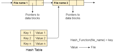
Fig 8 – Hash table
Key takeaway
There is the number of algorithms by using which, the directories can be implemented. However, the selection of an appropriate directory implementation algorithm may significantly affect the performance of the system.
The directory implementation algorithms are classified according to the data structure they are using. There are mainly two algorithms which are used in these days.
Now that we have discussed various block-allocation and directory management options, we can further consider their effect on performance and efficient disk use. Disks tend to represent a major bottleneck in system performance, since they are the slowest main computer component. In this section, we discuss a variety of techniques used to improve the efficiency and performance of secondary storage.
Efficiency
The efficient use of disk space depends heavily on the disk allocation and directory algorithms in use. For instance, UNIX inodes are pre allocated on a volume. Even an "empty" disk has a percentage of its space lost to inodes. However, by pre allocating the inodes and. spreading them across the volume, we improve the file system's performance. This improved performance results from the UNIX allocation and free-space algorithms, which try to keep a file's data blocks near that file's inode block to reduce seek time. As another example, let's reconsider the clustering scheme discussed in Section 11.4, which aids in file-seek and file-transfer performance at the cost of internal fragmentation.
To reduce this fragmentation, BSD UNIX varies the cluster size as a file grows. Large clusters are used where they can be filled, and small clusters are used for small files and the last cluster of a file. This system is described in Appendix A. The types of data normally kept in a file's directory (or inode) entry also require consideration. Commonly, a 'last write date" is recorded to supply information to the user and, to determine whether the file needs to be backed up. Some systems also keep a "last access date," so that a user can determine when the file was last read.
The result of keeping this information is that, whenever the file is read, a field in the directory structure must be written to. That means the block must be read into memory, a section changed, and the block written back out to disk, because operations on disks occur only in block (or cluster) chunks. So any time a file is opened for reading, its directory entry must be read and written as well. This requirement can be inefficient for frequently accessed files, so we must weigh its benefit against its performance cost when designing a file system. Generally, every data item associated with a file needs to be considered for its effect on efficiency and performance.
As an example, consider how efficiency is affected by the size of the pointers used to access data. Most systems use either 16- or 32-bit pointers throughout the operating system. These pointer sizes limit the length of a file to either 2 16 (64 KB) or 232 bytes (4 GB). Some systems implement 64-bit pointers to increase this limit to 264 bytes, which is a very large number indeed. However, 64-bit pointers take more space to store and in turn make the allocation and free-space-management methods (linked lists, indexes, and so on) use more disk space. One of the difficulties in choosing a pointer size, or indeed any fixed allocation size within an operating system, is planning for the effects of changing technology. Consider that the IBM PC XT had a 10-MB hard drive and an MS-DOS file system that could support only 32 MB. (Each FAT entry was 12 bits, pointing to an 8-KB cluster.)
As disk capacities increased, larger disks had to be split into 32-MB partitions, because the file system could not track blocks beyond 32 MB. As hard disks with capacities of over 100 MB became common, most disk controllers include local memory to form an on-board cache that is large enough to store entire tracks at a time. Once a seek is performed, the track is read into the disk cache starting at the sector under the disk head (reducing latency time).
The disk controller then transfers any sector requests to the operating system. Once blocks make it from the disk controller into main memory, the operating system may cache the blocks there. Some systems maintain a separate section of main memory for a buffer cache, where blocks are kept under the assumption that they will be used again shortly. Other systems cache file data using a page cache.
The page cache uses virtual memory techniques to cache file data as pages rather than as file-system-oriented blocks. Caching file data using virtual addresses is far more efficient than caching through physical disk blocks, as accesses interface with virtual memory rather than the file system. Several systems—including Solaris, Linux, and Windows NT, 2000, and XP—use page caching to cache both process pages and file data. This is known as unified virtual memory. Some versions of UNIX and Linux provide a unified buffer cache. To illustrate the benefits of the unified buffer cache, consider the two alternatives for opening and accessing a file. One approach is to use memory mapping (Section 9.7); the second is to use the standard system calls readO and write 0 . Without a unified buffer cache, we have a situation similar to Figure 11.11.
Here, the read() and write () system calls go through the buffer cache. The memory-mapping call, however, requires using two caches—the page cache and the buffer cache. A memory mapping proceeds by reading in disk blocks from the file system and storing them in the buffer cache. Because the virtual memory system does not interface with the buffer cache, the contents of the file in the buffer cache must be copied into the page cache. This situation is known as double caching and requires caching file-system data twice. Not only does it waste memory but it also wastes significant CPU and I/O cycles due to the extra data movement within, system memory.
In add ition, inconsistencies between the two caches can result in corrupt files. In contrast, when a unifiedthe disk data structures and algorithms in MS-DOS had to be modified to allow larger file systems. (Each FAT entry was expanded to 16 bits and later to 32 bits.) The initial file-system decisions were made for efficiency reasons; however, with the advent of MS-DOS version 4, millions of computer users were inconvenienced when they had to switch to the new, larger file system. Sun's ZFS file system uses 128-bit pointers, which theoretically should never need to be extended. (The minimum mass of a device capable of storing 2'2S bytes using atomic-level storage would be about 272 trillion kilograms.) As another example, consider the evolution of Sun's Solaris operating system.
Originally, many data structures were of fixed length, allocated at system start-up. These structures included the process table and the open-file table. When the process table became full, no more processes could be created. When the file table became full, no more files could be opened. The system would fail to provide services to users. Table sizes could be increased only by recompiling the kernel and rebooting the system. Since the release of Solaris 2, almost all kernel structures have been allocated dynamically, eliminating these artificial limits on system performance. Of course, the algorithms that manipulate these tables are more complicated, and the operating system is a little slower because it must dynamically allocate and deallocate table entries; but that price is the usual one for more general, functionality.
Performance
Even after the basic file-system algorithms have been selected, we can still improve performance in several ways. As will be discussed in Chapter 13, most disk controllers include local memory to form an on-board cache that is large enough to store entire tracks at a time. Once a seek is performed, the track is read into the disk cache starting at the sector under the disk head (reducing latency time). The disk controller then transfers any sector requests to the operating system. Once blocks make it from the disk controller into main memory, the operating system may cache the blocks there. Some systems maintain a separate section of main memory for a buffer cache, where blocks are kept under the assumption that they will be used again shortly. Other systems cache file data using a page cache.
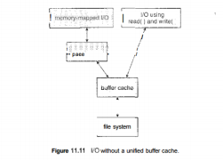
Fig 9 – I/O without a unified buffer cache
The page cache uses virtual memory techniques to cache file data as pages rather than as file-system-oriented blocks. Caching file data using virtual addresses is far more efficient than caching through physical disk blocks, as accesses interface with virtual memory rather than the file system. Several systems—including Solaris, Linux, and Windows NT, 2000, and XP—use page caching to cache both process pages and file data. This is known as unified virtual memory. Some versions of UNIX and Linux provide a unified buffer cache.
To illustrate the benefits of the unified buffer cache, consider the two alternatives for opening and accessing a file. One approach is to use memory mapping (Section 9.7); the second is to use the standard system calls readO and write 0 .
Without a unified buffer cache, we have a situation similar to Figure 11.11. Here, the read() and write () system calls go through the buffer cache. The memory-mapping call, however, requires using two caches—the page cache and the buffer cache. A memory mapping proceeds by reading in disk blocks from the file system and storing them in the buffer cache. Because the virtual memory system does not interface with the buffer cache, the contents of the file in the buffer cache must be copied into the page cache.
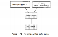
Fig 10 – I/O using a unified buffer cache
This situation is known as double caching and requires caching file-system data twice. Not only does it waste memory but it also wastes significant CPU and I/O cycles due to the extra data movement within, system memory. In add ition, inconsistencies between the two caches can result in corrupt files. In contrast, when a unified buffer cache is provided, both memory mapping and the read () and write () system calls use the same page cache. This has the benefit of avoiding double caching, and it allows the virtual memory system to manage file-system data. The unified buffer cache is shown in Figure 11.12. Regardless of whether we are caching disk blocks or pages (or both), LEU (Section 9.4.4) seems a reasonable general-purpose algorithm for block or page replacement. However, the evolution of the Solaris page-caching algorithms reveals the difficulty in choosing an algorithm. Solaris allows processes and the page cache to share unused inemory.
Versions earlier than Solaris 2.5.1 made no distinction between allocating pages to a process and allocating them to the page cache. As a result, a system performing many I/O operations used most of the available memory for caching pages. Because of the high rates of I/O, the page scanner (Section 9.10.2) reclaimed pages from processes— rather than from the page cache—when free memory ran low. Solaris 2.6 and Solaris 7 optionally implemented priority paging, in which the page scanner gives priority to process pages over the page cache. Solaris 8 applied a fixed limit to process pages and the file-system page cache, preventing either from forcing the other out of memory. Solaris 9 and 10 again changed the algorithms to maximize memory use and minimize thrashing. This real-world example shows the complexities of performance optimizing and caching.
There are other issvies that can affect the performance of I/O such as whether writes to the file system occur synchronously or asynchronously. Synchronous writes occur in the order in which the disk subsystem receives them, and the writes are not buffered. Thus, the calling routine must wait for the data to reach the disk drive before it can proceed. Asynchronous writes are done the majority of the time. In an asynchronous write, the data are stored in the cache, and control returns to the caller. Metadata writes, among others, can be synchronous.
Operating systems frequently include a flag in the open system call to allow a process to request that writes be performed synchronously. For example, databases use this feature for atomic transactions, to assure that data reach stable storage in the required order. Some systems optimize their page cache by using different replacement algorithms, depending on the access type of the file.
A file being read or written sequentially should not have its pages replaced in LRU order, because the most 11.7 Recovery 435 recently used page will be used last, or perhaps never again. Instead, sequential access can be optimized by techniques known as free-behind and read-ahead. Free-behind removes a page from the buffer as soon as the next page is requested. The previous pages are not likely to be used again and waste buffer space. With read-ahead, a requested page and several subsequent pages are read and cached. These pages are likely to be requested after the current page is processed.
Retrieving these data from the disk in one transfer and caching them saves a considerable amount of time. One might think a track cache on the controller eliminates the need for read-ahead on a multiprogrammed system. However, because of the high latency and overhead involved in making many small transfers from the track cache to main memory, performing a read-ahead remains beneficial. The page cache, the file system, and the disk drivers have some interesting interactions. When data are written to a disk file, the pages are buffered in the cache, and the disk driver sorts its output queue according to disk address. These two actions allow the disk driver to minimize disk-head seeks and to write data at times optimized for disk rotation.
Unless synchronous writes are required, a process writing to disk simply writes into the cache, and the system asynchronously writes the data to disk when convenient. The user process sees very fast writes. When data are read from a disk file, the block I/O system does some read-ahead; however, writes are much more nearly asynchronous than are reads. Thus, output to the disk through the file system is often faster than is input for large transfers, counter to intuition.
Key takeaway
Now that we have discussed various block-allocation and directory management options, we can further consider their effect on performance and efficient disk use. Disks tend to represent a major bottleneck in system performance, since they are the slowest main computer component. In this section, we discuss a variety of techniques used to improve the efficiency and performance of secondary storage.
Modern disk drives are addressed as large one-dimensional arrays of logical blocks, where the logical block is the smallest unit of transfer. The size of a logical block is usually 512 bytes, although some disks can be low-level formatted to have a different logical block size, such as 1,024 bytes. This option is described in Section 12.5.1. The one-dimensional array of logical blocks is mapped onto the sectors of the disk sequentially. Sector 0 is the first sector of the first track on the outermost cylinder.
The mapping proceeds in order through that track, then through the rest of the tracks in that cylinder, and then through the rest of the cylinders from outermost to innermost. By using this mapping, we can—at least in theory—convert a logical block number into an old-style disk address that consists of a cylinder number, a track number within that cylinder, and a sector number within that track. In practice, it is difficult to perform, this translation, for two reasons. First, most disks have some defective sectors, but the mapping hides this by substituting spare sectors from elsewhere on the disk. Second, the number of sectors per track is not a constant on some drives.
Let's look more closely at the second reason. On media that use constant linear velocity (CLV), the density of bits per track is uniform. The farther a track is from the centre of the disk, the greater its length, so the more sectors it can hold. As we move from outer zones to inner zones, the number of sectors per track decreases. Tracks in the outermost zone typically hold 40 percent more sectors than do tracks in the innermost zone. The drive increases its rotation speed as the head moves from the outer to the inner tracks to keep the same rate of data moving under the head.
This method is used in CD-ROM and DVD-ROM drives. Alternatively, the disk rotation speed can stay constant, and the density of bits decreases from inner tracks to outer tracks to keep the data rate constant. This method is used in hard disks and is known as constant angular velocity (CAV). The number of sectors per track has been increasing as disk technology improves, and the outer zone of a disk usually has several hundred sectors per track. Similarly, the number of cylinders per disk has been increasing; large disks have tens of thousands of cylinders.
Key takeaway
Modern disk drives are addressed as large one-dimensional arrays of logical blocks, where the logical block is the smallest unit of transfer. The size of a logical block is usually 512 bytes, although some disks can be low-level formatted to have a different logical block size, such as 1,024 bytes. This option is described in Section 12.5.1. The one-dimensional array of logical blocks is mapped onto the sectors of the disk sequentially. Sector 0 is the first sector of the first track on the outermost cylinder.
As we know, a process needs two type of time, CPU time and IO time. For I/O, it requests the Operating system to access the disk.
However, the operating system must be fair enough to satisfy each request and at the same time, operating system must maintain the efficiency and speed of process execution.
The technique that operating system uses to determine the request which is to be satisfied next is called disk scheduling.
Let's discuss some important terms related to disk scheduling.
Seek time is the time taken in locating the disk arm to a specified track where the read/write request will be satisfied.
It is the time taken by the desired sector to rotate itself to the position from where it can access the R/W heads.
It is the time taken to transfer the data.
Disk access time is given as,
Disk Access Time = Rotational Latency + Seek Time + Transfer Time
It is the average of time spent by each request waiting for the IO operation.
The main purpose of disk scheduling algorithm is to select a disk request from the queue of IO requests and decide the schedule when this request will be processed.
Goal of Disk Scheduling Algorithm
The list of various disks scheduling algorithm is given below. Each algorithm is carrying some advantages and disadvantages. The limitation of each algorithm leads to the evolution of a new algorithm.
It is the simplest Disk Scheduling algorithm. It services the IO requests in the order in which they arrive. There is no starvation in this algorithm, every request is serviced.
Consider the following disk request sequence for a disk with 100 tracks 45, 21, 67, 90, 4, 50, 89, 52, 61, 87, 25
Head pointer starting at 50 and moving in left direction. Find the number of head movements in cylinders using FCFS scheduling.
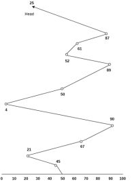
Number of cylinders moved by the head
= (50-45)+(45-21)+(67-21)+(90-67)+(90-4)+(50-4)+(89-50)+(61-52)+(87-61)+(87-25)
= 5 + 24 + 46 + 23 + 86 + 46 + 49 + 9 + 26 + 62
= 376
Shortest seek time first (SSTF) algorithm selects the disk I/O request which requires the least disk arm movement from its current position regardless of the direction. It reduces the total seek time as compared to FCFS.
It allows the head to move to the closest track in the service queue.
Consider the following disk request sequence for a disk with 100 tracks
45, 21, 67, 90, 4, 89, 52, 61, 87, 25
Head pointer starting at 50. Find the number of head movements in cylinders using SSTF scheduling.
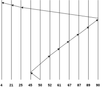
Number of cylinders = 5 + 7 + 9 + 6 + 20 + 2 + 1 + 65 + 4 + 17 = 136
It is also called as Elevator Algorithm. In this algorithm, the disk arm moves into a particular direction till the end, satisfying all the requests coming in its path and then it turns back and moves in the reverse direction satisfying requests coming in its path.
It works in the way an elevator works, elevator moves in a direction completely till the last floor of that direction and then turns back.
Consider the following disk request sequence for a disk with 100 tracks
98, 137, 122, 183, 14, 133, 65, 78
Head pointer starting at 54 and moving in left direction. Find the number of head movements in cylinders using SCAN scheduling.
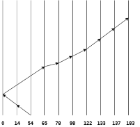
Number of Cylinders = 40 + 14 + 65 + 13 + 20 + 24 + 11 + 4 + 46 = 237
In C-SCAN algorithm, the arm of the disk moves in a particular direction servicing requests until it reaches the last cylinder, then it jumps to the last cylinder of the opposite direction without servicing any request then it turns back and start moving in that direction servicing the remaining requests.
Consider the following disk request sequence for a disk with 100 tracks
98, 137, 122, 183, 14, 133, 65, 78
Head pointer starting at 54 and moving in left direction. Find the number of head movements in cylinders using C-SCAN scheduling.
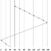
No. of cylinders crossed = 40 + 14 + 199 + 16 + 46 + 4 + 11 + 24 + 20 + 13 = 387
Key takeaway
As we know, a process needs two type of time, CPU time and IO time. For I/O, it requests the Operating system to access the disk.
However, the operating system must be fare enough to satisfy each request and at the same time, operating system must maintain the efficiency and speed of process execution.
The technique that operating system uses to determine the request which is to be satisfied next is called disk scheduling.
It is important to understand the terms reliability and performance as they pertain to disks. Reliability is the ability of the disk system to accommodate a single- or multi-disk failure and still remain available to the users. Performance is the ability of the disks to efficiently provide information to the users.
Adding redundancy almost always increases the reliability of the disk system. The most common way to add redundancy is to implement a Redundant Array of Inexpensive Disks (RAID).
There are two types of RAID:
Hardware — The most commonly used hardware RAID levels are: RAID 0, RAID 1, RAID 5, and RAID 10. The main differences between these RAID levels focus on reliability and performance as previously defined.
Software — Software RAID can be less expensive. However, it is almost always much slower than hardware RAID, because it places a burden on the main system CPU to manage the extra disk I/O.
The different hardware RAID types are as follows:
RAID 0 (Striping) — RAID 0 has the following characteristics:
High performance — Performance benefit for randomized reads and writes
Low reliability — No failure protection
Increased risk — If one disk fails, the entire set fails
The disks work together to send information to the user. While this arrangement does help performance, it can cause a potential problem. If one disk fails, the entire file system is corrupted.
RAID 1 (Mirroring) — RAID 1 has the following characteristics:
Medium performance — Superior to conventional disks due to "optimistic read"
Expensive — Requires twice as many disks to achieve the same storage, and also requires twice as many controllers if you want redundancy at that level
High reliability — Loses a disk without an outage
Good for sequential reads and writes — The layout of the disk and the layout of the data are sequential, promoting a performance benefit, provided you can isolate a sequential file to a mirror pair
In a two disk RAID 1 system, the first disk is the primary disk and the second disk acts as the parity, or mirror disk. The role of the parity disk is to keep an exact synchronous copy of all the information stored on the primary disk. If the primary disk fails, the information can be retrieved from the parity disk.
Be sure that your disks are able to be hot swapped so repairs can be made without bringing down the system. Remember that there is a performance penalty during the resynchronization period of the disks.
On a read, the disk that has its read/write heads positioned closer to the data will retrieve information. This data retrieval technique is known as an optimistic read. An optimistic read can provide a maximum of 15 percent improvement in performance over a conventional disk. When setting up mirrors, it is important to consider which physical disks are being used for primary and parity information, and to balance the I/O across physical disks rather than logical disks.
RAID 10 or 1+0 — RAID 10 has the following characteristics:
High reliability — Provides mirroring and striping
High performance — Good for randomized reads and writes.
Low cost — No more expensive than RAID 1 mirroring
RAID 10 resolves the reliability problem of striping by adding mirroring to the equation.
Note: If you are implementing a RAID solution, Progress Software Corporation recommends RAID 10.
RAID 5 — RAID 5 has the following characteristics:
High reliability — Provides good failure protection
Low performance — Performance is poor for writes due to the parity's construction
Absorbed state — Running in an absorbed state provides diminished performance throughout the application because the information must be reconstructed from parity
Caution: Progress Software Corporation recommends not using RAID 5 for database systems.
It is possible to have both high reliability and high performance. However, the cost of a system that delivers both of these characteristics is higher than a system that is only delivers one of the two.
Key takeaway
It is important to understand the terms reliability and performance as they pertain to disks. Reliability is the ability of the disk system to accommodate a single- or multi-disk failure and still remain available to the users. Performance is the ability of the disks to efficiently provide information to the users.
Disk formatting is a process to configure the data-storage devices such as hard-drive, floppy disk and flash drive when we are going to use them for the very first time or we can say initial usage. Disk formatting is usually required when new operating system is going to be used by the user. It is also done when there is space issue and we require additional space for the storage of more data in the drives. When we format the disk then the existing files within the disk is also erased.
We can perform disk formatting on both magnetic platter hard-drives and solid-state drives.
When we are going to use hard-drive for initial use it is going to search for virus. It can scan for virus and repair the bad sectors within the drive. Disk formatting has also the capability to erase the bad applications and various sophisticated viruses.
As we know that disk formatting deletes data and removes all the programs installed within the drive. So it can be done with caution. We must have the backup of all the data and applications which we require. No-doubt disk formatting requires time. But the frequent formatting of the disk decreases the life of the hard-drive.
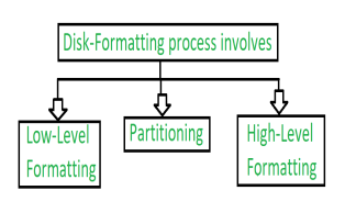
Fig 11 – Formatting process of disk
1. Low-level Formatting:
Low level formatting is a type of physical formatting. In is the process of marking of cylinders and tracks of the blank hard-disk. After this there is the division of tracks into sectors with the sector markers. Now-a-days low-level formatting is performed by the hard-disk manufactures themselves.
We have data in our hard-disks and when we perform low-level formatting in the presence of data in the hard-disk all the data have been erased and it is impossible to recover that data. Some users make such a format that they can avoid their privacy leakage. Otherwise low-level will cause damage to hard-disk shortens the service-life.
Therefore, this formatting is not suggested to users.
2. Partitioning:
As suggesting from the name, partitioning means divisions. Partitioning is the process of dividing the hard-disk into one or more regions. The regions are called as partitions.
It can be performed by the users and it will affect the disk performance.
3. High-level Formatting:
High-level formatting is the process of writing. Writing on a file system, cluster size, partition label, and so on for a newly created partition or volume. It is done to erase the hard-disk and again installing the operating system on the disk-drive.
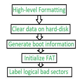
Fig 12 – Steps of High-level Formatting
Firstly, High-level formatting clears the data on hard-disk, then it will generate boot information, the it will initialize FAT after this it will go for label logical bad sectors when partition has existed.
Formatting done by the user is the high-level formatting.
Generally, it does not harm the hard-disk. It can be done easily with the Administrator, Windows snap-in Disk Management tool, disk part, etc.
We can use such a format to use such a format to fix some problems like errors in the file system, corrupted hard-drive and develop bad sectors.
Key takeaway
Disk formatting is a process to configure the data-storage devices such as hard-drive, floppy disk and flash drive when we are going to use them for the very first time or we can say initial usage. Disk formatting is usually required when new operating system is going to be used by the user. It is also done when there is space issue and we require additional space for the storage of more data in the drives. When we format the disk then the existing files within the disk is also erased.
Boot Block in Operating System
Basically for a computer to start running to get an instance when it is powered up or rebooted it need to have an initial program to run. And this initial program which is known as bootstrap need to be simple. It must initialize all aspects of the system, from CPU registers to device controllers and the contents of the main memory and then starts the operating system.
To do this job the bootstrap program basically finds the operating system kernel on disk and then loads the kernel into memory and after this, it jumps to the initial address to begin the operating-system execution.
Why ROM:
For most of today’s computer bootstrap is stored in Read Only Memory (ROM).
The problem is that changing the bootstrap code basically requires changes in the ROM hardware chips. Because of this reason, most system nowadays has the tiny bootstrap loader program in the boot whose only job is to bring the full bootstrap program from the disk. Through this now we are able to change the full bootstrap program easily and the new version can be easily written onto the disk.
Full bootstrap program is stored in the boot blocks at a fixed location on the disk. A disk which has a boot partition is called a boot disk. The code in the boot ROM basically instructs the read controller to read the boot blocks into the memory and then starts the execution of code. The full bootstrap program is more complex than the bootstrap loader in the boot ROM, It is basically able to load the complete OS from a non-fixed location on disk to start the operating system running. Even though the complete bootstrap program is very small.
Example:
Let us try to understand this using an example of the boot process in Windows 2000.
The Windows 2000 basically stores its boot code in the first sector on the hard disk. Moreover, Windows 2000 allows the hard disk to be divided into one or more partitions. In this one partition is basically identified as the boot partition which basically contains the operating system and the device drivers.
Booting in Windows 2000 starts by running the code that is placed in the system’s ROM memory. This code directs the system to read code directly from MBR. In addition to this, boot code also contains the table which lists the partition for the hard disk and also a flag that indicates which partition is to be boot from the system. Once the system identifies the boot partition it reads the first sector from the memory which is known as boot sector and continue the process with the remainder of the boot process which includes loading of various system services.
The following figure shows the Booting from disk in Windows 2000.
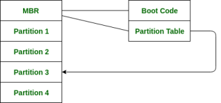
Fig 13 - Booting from disk
Bad Block in Operating system
Bad Block is an area of storing media that is no longer reliable for the storage of data because it is completely damaged or corrupted.
We know disk have moving parts and have small tolerances, they are prone to failure. In case when the failure is complete, then the disk needs to be replaced and its contents restored from backup media to the new disk. More frequently, one or more sectors become defective. More disks even come from the factory named Bad blocks.
This is also referred to as Bad Sector.
Cause of Bad Block:
Storage drives can ship from the factory with defective blocks that originated in the manufacturing process. The device with bad-blocks are marked as defective before leaving the factory. These are remapped with the available extra memory cells.
A physical damage to device also makes a device as bad block because sometimes operating system does not able to access the data. Dropping a laptop will also cause damage to the platter of the HDD’s. Sometimes dust also cause damage to HDD’s.
When the memory transistor fails it will cause damage to the solid-state drive. Storage cells can also become unreliable over time, as NAND flash substrate in a cell becomes unusable after a certain number of program-erase cycles.
For the erase process on the solid-state drive it requires a huge amount of electrical charge through the flash cards. This degrades the oxide layer that separates the floating gate transistors from the flash memory silicon substrate and the bit error rates increase. The drive’s controller can use error detection and correction mechanisms to fix these errors. However, at some point, the errors can outstrip the controller’s ability to correct them and the cell can become unreliable.
Soft bad sectors are caused by software problems. For instance, if a computer unexpectedly shuts down, due to this, hard drive also turn of in the middle of writing to a block. Due to this, the data contain in the block doesn’t match with the CRC detection error code and it would marked as bad sector.
Types of Bad Blocks:
There are two types of bad blocks –
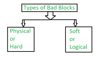
It comes from damage to the storage medium.
2. Soft or Logical bad block:
A soft, or logical, bad block occurs when the operating system (OS) is unable to read data from a sector.
Example –
A soft bad block include when the cyclic redundancy check (CRC), or error correction code (ECC), for a particular storage block does not match the data read by the disk.
How Bad blocks are handled:
These blocks are handled in a number of ways, but it depends upon the disk and controller.
On simple disks, such as some disks with IDE controller, bad blocks are handled manually. One strategy is to scan the disk to find bad blocks while disk is being formatted. Any bad block that are discovered as flagged as unusable so that file system does not allocate them. If blocks go bad during normal operation, a special program (such as the Linux bad blocks command) must be run manually to search for the bad blocks and to lock them away.
More sophisticated disks are smarter about bad-block recovery. The work of controller is to maintain the list of bad blocks. The list formed by the controller is initialized during the low-level formatting at the factory and is updated over the life of the disk. Low-level formatting holds the spare sectors which are not visible to the operating system. The last task is done by controller which is to replace each bad sector logically with the spare sectors. This scheme is also known as sector sparing and forwarding.
A typical bad-sector transaction is as follows –
Note –
The redirection by the controller (i.e., the request translated to replacement) could invalidate any optimization by the operating system’s disk-scheduling algorithm. For this reason, most disks are formatted to provide a few spare sectors in each cylinder and spare cylinder as well. Whenever the bad block is going to remap, the controller will use spare sector from the same cylinder, if possible; otherwise spare cylinder is also present.
Some controllers use spare sector to replace bad block, there is also another technique to replace bad block which is sector slipping.
Example of sector slipping –
Suppose that logical block 16 becomes defective and the first available spare sector follows sector 200. Sector slipping then starts remapping. All the sectors from 16 to 200, moving them all down one spot. That is, sector 200 is copied into the spare, then sector 199 into 200, then 198 into 199, and so on, until sector 17 is copied into sector 18.
In this way slipping the sectors frees up the space of sector 17 so that sector 16 can be mapped to it.
The replacement of bad block is not totally automatic, because data in the bad block are usually lost. A process is trigger by the soft errors in which a copy of the block data is made and the block is spared or slipped. Hard error which is unrecoverable will lost all its data. Whatever file was using that block must be repaired and that requires manual intervention.
Key takeaway
Basically for a computer to start running to get an instance when it is powered up or rebooted it need to have an initial program to run. And this initial program which is known as bootstrap need to be simple. It must initialize all aspects of the system, from CPU registers to device controllers and the contents of the main memory and then starts the operating system.
One of the important jobs of an Operating System is to manage various I/O devices including mouse, keyboards, touch pad, disk drives, display adapters, USB devices, Bit-mapped screen, LED, Analog-to-digital converter, On/off switch, network connections, audio I/O, printers etc.
An I/O system is required to take an application I/O request and send it to the physical device, then take whatever response comes back from the device and send it to the application. I/O devices can be divided into two categories −
Device drivers are software modules that can be plugged into an OS to handle a particular device. Operating System takes help from device drivers to handle all I/O devices.
The Device Controller works like an interface between a device and a device driver. I/O units (Keyboard, mouse, printer, etc.) typically consist of a mechanical component and an electronic component where electronic component is called the device controller.
There is always a device controller and a device driver for each device to communicate with the Operating Systems. A device controller may be able to handle multiple devices. As an interface its main task is to convert serial bit stream to block of bytes, perform error correction as necessary.
Any device connected to the computer is connected by a plug and socket, and the socket is connected to a device controller. Following is a model for connecting the CPU, memory, controllers, and I/O devices where CPU and device controllers all use a common bus for communication.
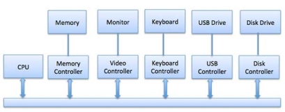
Fig 14 – Control devices
Synchronous vs asynchronous I/O
The CPU must have a way to pass information to and from an I/O device. There are three approaches available to communicate with the CPU and Device.
This uses CPU instructions that are specifically made for controlling I/O devices. These instructions typically allow data to be sent to an I/O device or read from an I/O device.
When using memory-mapped I/O, the same address space is shared by memory and I/O devices. The device is connected directly to certain main memory locations so that I/O device can transfer block of data to/from memory without going through CPU.
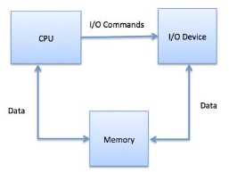
Fig 15 – Process state
While using memory mapped IO, OS allocates buffer in memory and informs I/O device to use that buffer to send data to the CPU. I/O device operates asynchronously with CPU, interrupts CPU when finished.
The advantage to this method is that every instruction which can access memory can be used to manipulate an I/O device. Memory mapped IO is used for most high-speed I/O devices like disks, communication interfaces.
Slow devices like keyboards will generate an interrupt to the main CPU after each byte is transferred. If a fast device such as a disk generated an interrupt for each byte, the operating system would spend most of its time handling these interrupts. So a typical computer uses direct memory access (DMA) hardware to reduce this overhead.
Direct Memory Access (DMA) means CPU grants I/O module authority to read from or write to memory without involvement. DMA module itself controls exchange of data between main memory and the I/O device. CPU is only involved at the beginning and end of the transfer and interrupted only after entire block has been transferred.
Direct Memory Access needs a special hardware called DMA controller (DMAC) that manages the data transfers and arbitrates access to the system bus. The controllers are programmed with source and destination pointers (where to read/write the data), counters to track the number of transferred bytes, and settings, which includes I/O and memory types, interrupts and states for the CPU cycles.
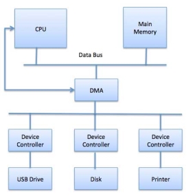
Fig 16 - DMA
The operating system uses the DMA hardware as follows −
Step | Description |
1 | Device driver is instructed to transfer disk data to a buffer address X. |
2 | Device driver then instruct disk controller to transfer data to buffer. |
3 | Disk controller starts DMA transfer. |
4 | Disk controller sends each byte to DMA controller. |
5 | DMA controller transfers bytes to buffer, increases the memory address, decreases the counter C until C becomes zero. |
6 | When C becomes zero, DMA interrupts CPU to signal transfer completion. |
A computer must have a way of detecting the arrival of any type of input. There are two ways that this can happen, known as polling and interrupts. Both of these techniques allow the processor to deal with events that can happen at any time and that are not related to the process it is currently running.
Polling is the simplest way for an I/O device to communicate with the processor. The process of periodically checking status of the device to see if it is time for the next I/O operation, is called polling. The I/O device simply puts the information in a Status register, and the processor must come and get the information.
Most of the time, devices will not require attention and when one does it will have to wait until it is next interrogated by the polling program. This is an inefficient method and much of the processors time is wasted on unnecessary polls.
Compare this method to a teacher continually asking every student in a class, one after another, if they need help. Obviously the more efficient method would be for a student to inform the teacher whenever they require assistance.
An alternative scheme for dealing with I/O is the interrupt-driven method. An interrupt is a signal to the microprocessor from a device that requires attention.
A device controller puts an interrupt signal on the bus when it needs CPU’s attention when CPU receives an interrupt, It saves its current state and invokes the appropriate interrupt handler using the interrupt vector (addresses of OS routines to handle various events). When the interrupting device has been dealt with, the CPU continues with its original task as if it had never been interrupted.
Key takeaway
One of the important jobs of an Operating System is to manage various I/O devices including mouse, keyboards, touch pad, disk drives, display adapters, USB devices, Bit-mapped screen, LED, Analog-to-digital converter, On/off switch, network connections, audio I/O, printers etc.
An I/O system is required to take an application I/O request and send it to the physical device, then take whatever response comes back from the device and send it to the application.
I/O software is often organized in the following layers −
A key concept in the design of I/O software is that it should be device independent where it should be possible to write programs that can access any I/O device without having to specify the device in advance. For example, a program that reads a file as input should be able to read a file on a floppy disk, on a hard disk, or on a CD-ROM, without having to modify the program for each different device.
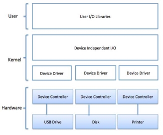
Fig 17 - Example
Device drivers are software modules that can be plugged into an OS to handle a particular device. Operating System takes help from device drivers to handle all I/O devices. Device drivers encapsulate device-dependent code and implement a standard interface in such a way that code contains device-specific register reads/writes. Device driver, is generally written by the device's manufacturer and delivered along with the device on a CD-ROM.
A device driver performs the following jobs −
How a device driver handles a request is as follows: Suppose a request comes to read a block N. If the driver is idle at the time a request arrives, it starts carrying out the request immediately. Otherwise, if the driver is already busy with some other request, it places the new request in the queue of pending requests.
An interrupt handler, also known as an interrupt service routine or ISR, is a piece of software or more specifically a callback function in an operating system or more specifically in a device driver, whose execution is triggered by the reception of an interrupt.
When the interrupt happens, the interrupt procedure does whatever it has to in order to handle the interrupt, updates data structures and wakes up process that was waiting for an interrupt to happen.
The interrupt mechanism accepts an address ─ a number that selects a specific interrupt handling routine/function from a small set. In most architectures, this address is an offset stored in a table called the interrupt vector table. This vector contains the memory addresses of specialized interrupt handlers.
Device-Independent I/O Software
The basic function of the device-independent software is to perform the I/O functions that are common to all devices and to provide a uniform interface to the user-level software. Though it is difficult to write completely device independent software but we can write some modules which are common among all the devices. Following is a list of functions of device-independent I/O Software −
These are the libraries which provide richer and simplified interface to access the functionality of the kernel or ultimately interactive with the device drivers. Most of the user-level I/O software consists of library procedures with some exception like spooling system which is a way of dealing with dedicated I/O devices in a multiprogramming system.
I/O Libraries (e.g., stdio) are in user-space to provide an interface to the OS resident device-independent I/O SW. For example putchar(), getchar(), printf() and scanf() are example of user level I/O library stdio available in C programming.
Kernel I/O Subsystem is responsible to provide many services related to I/O. Following are some of the services provided.
Key takeaway
Basically, we want the programs and data to reside in main memory permanently.
This arrangement is usually not possible for the following two reasons:
There are two types of storage devices:-
It loses its contents when the power of the device is removed.
It does not lose its contents when the power is removed. It holds all the data when the power is removed.
Secondary storage is used as an extension of main memory. Secondary storage devices can hold the data permanently.
Storage devices consist of Registers, Cache, Main-Memory, Electronic-Disk, Magnetic Disk, Optical disk, Magnetic Tapes. Each storage system provides the basic system of storing a datum and of holding the datum until it is retrieved at a later time. All the storage devices differ in speed, cost, size and volatility. The most common Secondary-storage device is a Magnetic-disk, which provides storage for both programs and data.
In this fig Hierarchy of storage is shown –
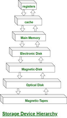
Fig 18 - Hierarchy of storage
In this hierarchy all the storage devices are arranged according to speed and cost. The higher levels are expensive, but they are fast. As we move down the hierarchy, the cost per bit generally decreases, whereas the access time generally increases.
The storage systems above the Electronic disk are Volatile, where as those below are Non-Volatile.
An Electronic disk can be either designed to be either Volatile or Non-Volatile. During normal operation, the electronic disk stores data in a large DRAM array, which is Volatile. But many electronic disk devices contain a hidden magnetic hard disk and a battery for backup power. If external power is interrupted, the electronic disk controller copies the data from RAM to the magnetic disk. When external power is restored, the controller copies the data back into the RAM.
The design of a complete memory system must balance all the factors. It must use only as much expensive memory as necessary while providing as much inexpensive, Non-Volatile memory as possible. Caches can be installed to improve performance where a large access-time or transfer-rate disparity exists between two components.
Key takeaway
Basically we want the programs and data to reside in main memory permanently.
This arrangement is usually not possible for the following two reasons:
References