Unit - 3
Network Layer
- When a user accesses the internet or another computer network outside their immediate location, messages are sent through the network of transmission media. This technique of transferring the information from one computer network to another network is known as switching.
- Switching in a computer network is achieved by using switches. A switch is a small hardware device which is used to join multiple computers together with one local area network (LAN).
- Network switches operate at layer 2 (Data link layer) in the OSI model.
- Switching is transparent to the user and does not require any configuration in the home network.
- Switches are used to forward the packets based on MAC addresses.
- A Switch is used to transfer the data only to the device that has been addressed. It verifies the destination address to route the packet appropriately.
- It is operated in full duplex mode.
- Packet collision is minimum as it directly communicates between source and destination.
- It does not broadcast the message as it works with limited bandwidth.
Why is Switching Concept required?
Switching concept is developed because of the following reasons:
- Bandwidth: It is defined as the maximum transfer rate of a cable. It is a very critical and expensive resource. Therefore, switching techniques are used for the effective utilization of the bandwidth of a network.
- Collision: Collision is the effect that occurs when more than one device transmits the message over the same physical media, and they collide with each other. To overcome this problem, switching technology is implemented so that packets do not collide with each other.
Advantages of Switching:
- Switch increases the bandwidth of the network.
- It reduces the workload on individual PCs as it sends the information to only that device which has been addressed.
- It increases the overall performance of the network by reducing the traffic on the network.
- There will be less frame collision as switch creates the collision domain for each connection.
Disadvantages of Switching:
- A Switch is more expensive than network bridges.
- A Switch cannot determine the network connectivity issues easily.
- Proper designing and configuration of the switch are required to handle multicast packets.
Switching Modes
- The layer 2 switches are used for transmitting the data on the data link layer, and it also performs error checking on transmitted and received frames.
- The layer 2 switches forward the packets with the help of MAC address.
- Different modes are used for forwarding the packets known as Switching modes.
- In switching mode, Different parts of a frame are recognized. The frame consists of several parts such as preamble, destination MAC address, source MAC address, user's data, FCS.

Fig 1 – Switching mode
There are three types of switching modes:
- Store-and-forward
- Cut-through
- Fragment-free

Store-and-forward

Fig 2 – Store and forward
- Store-and-forward is a technique in which the intermediate nodes store the received frame and then check for errors before forwarding the packets to the next node.
- The layer 2 switch waits until the entire frame has received. On receiving the entire frame, switch store the frame into the switch buffer memory. This process is known as storing the frame.
- When the frame is stored, then the frame is checked for the errors. If any error found, the message is discarded otherwise the message is forwarded to the next node. This process is known as forwarding the frame.
- CRC (Cyclic Redundancy Check) technique is implemented that uses a number of bits to check for the errors on the received frame.
- The store-and-forward technique ensures a high level of security as the destination network will not be affected by the corrupted frames.
- Store-and-forward switches are highly reliable as it does not forward the collided frames.
Cut-through Switching

Fig 3 – Cut through
- Cut-through switching is a technique in which the switch forwards the packets after the destination address has been identified without waiting for the entire frame to be received.
- Once the frame is received, it checks the first six bytes of the frame following the preamble, the switch checks the destination in the switching table to determine the outgoing interface port, and forwards the frame to the destination.
- It has low latency rate as the switch does not wait for the entire frame to be received before sending the packets to the destination.
- It has no error checking technique. Therefore, the errors can be sent with or without errors to the receiver.
- A Cut-through switching technique has low wait time as it forwards the packets as soon as it identifies the destination MAC address.
- In this technique, collision is not detected, if frames have collided will also be forwarded.
Fragment-free Switching

Fig 4 – Fragment free
- A Fragment-free switching is an advanced technique of the Cut-through Switching.
- A Fragment-free switching is a technique that reads atleast 64 bytes of a frame before forwarding to the next node to provide the error-free transmission.
- It combines the speed of Cut-through Switching with the error checking functionality.
- This technique checks the 64 bytes of the ethernet frame where addressing information is available.
- A collision is detected within 64 bytes of the frame, the frames which are collided will not be forwarded further.
Differences b/w Store-and-forward and Cut-through Switching.
Store-and-forward Switching | Cut-through Switching |
Store-and-forward Switching is a technique that waits until the entire frame is received. | Cut-through Switching is a technique that checks the first 6 bytes following the preamble to identify the destination address. |
It performs error checking functionality. If any error is found in the frame, the frame will be discarded otherwise forwarded to the next node. | It does not perform any error checking. The frame with or without errors will be forwarded. |
It has high latency rate as it waits for the entire frame to be received before forwarding to the next node. | It has low latency rate as it checks only six bytes of the frame to determine the destination address. |
It is highly reliable as it forwards only error-free packets. | It is less reliable as compared to Store-and-forward technique as it forwards error prone packets as well. |
It has a high wait time as it waits for the entire frame to be received before taking any forwarding decisions. | It has low wait time as cut-through switches do not store the whole frame or packets. |
Switching techniques
In large networks, there can be multiple paths from sender to receiver. The switching technique will decide the best route for data transmission.
Switching technique is used to connect the systems for making one-to-one communication.
Classification Of Switching Techniques
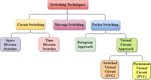
Fig 5 – Switching techniques
Circuit Switching
- Circuit switching is a switching technique that establishes a dedicated path between sender and receiver.
- In the Circuit Switching Technique, once the connection is established then the dedicated path will remain to exist until the connection is terminated.
- Circuit switching in a network operates in a similar way as the telephone works.
- A complete end-to-end path must exist before the communication takes place.
- In case of circuit switching technique, when any user wants to send the data, voice, video, a request signal is sent to the receiver then the receiver sends back the acknowledgment to ensure the availability of the dedicated path. After receiving the acknowledgment, dedicated path transfers the data.
- Circuit switching is used in public telephone network. It is used for voice transmission.
- Fixed data can be transferred at a time in circuit switching technology.
Communication through circuit switching has 3 phases:
- Circuit establishment
- Data transfer
- Circuit Disconnect
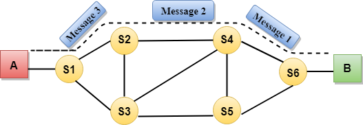
Fig 6 – Communication
Circuit Switching can use either of the two technologies:
Space Division Switches:
- Space Division Switching is a circuit switching technology in which a single transmission path is accomplished in a switch by using a physically separate set of crosspoints.
- Space Division Switching can be achieved by using crossbar switch. A crossbar switch is a metallic crosspoint or semiconductor gate that can be enabled or disabled by a control unit.
- The Crossbar switch is made by using the semiconductor. For example, Xilinx crossbar switch using FPGAs.
- Space Division Switching has high speed, high capacity, and nonblocking switches.
Space Division Switches can be categorized in two ways:
- Crossbar Switch
- Multistage Switch
Crossbar Switch
The Crossbar switch is a switch that has n input lines and n output lines. The crossbar switch has n2 intersection points known as crosspoints.
Disadvantage of Crossbar switch:
The number of crosspoints increases as the number of stations is increased. Therefore, it becomes very expensive for a large switch. The solution to this is to use a multistage switch.
Multistage Switch
- Multistage Switch is made by splitting the crossbar switch into the smaller units and then interconnecting them.
- It reduces the number of crosspoints.
- If one path fails, then there will be an availability of another path.
Advantages Of Circuit Switching:
- In the case of Circuit Switching technique, the communication channel is dedicated.
- It has fixed bandwidth.
Disadvantages Of Circuit Switching:
- Once the dedicated path is established, the only delay occurs in the speed of data transmission.
- It takes a long time to establish a connection approx 10 seconds during which no data can be transmitted.
- It is more expensive than other switching techniques as a dedicated path is required for each connection.
- It is inefficient to use because once the path is established and no data is transferred, then the capacity of the path is wasted.
- In this case, the connection is dedicated therefore no other data can be transferred even if the channel is free.
Message Switching
- Message Switching is a switching technique in which a message is transferred as a complete unit and routed through intermediate nodes at which it is stored and forwarded.
- In Message Switching technique, there is no establishment of a dedicated path between the sender and receiver.
- The destination address is appended to the message. Message Switching provides a dynamic routing as the message is routed through the intermediate nodes based on the information available in the message.
- Message switches are programmed in such a way so that they can provide the most efficient routes.
- Each and every node stores the entire message and then forward it to the next node. This type of network is known as store and forward network.
- Message switching treats each message as an independent entity.

Fig 7 – Message switching
Advantages Of Message Switching
- Data channels are shared among the communicating devices that improve the efficiency of using available bandwidth.
- Traffic congestion can be reduced because the message is temporarily stored in the nodes.
- Message priority can be used to manage the network.
- The size of the message which is sent over the network can be varied. Therefore, it supports the data of unlimited size.
Disadvantages Of Message Switching
- The message switches must be equipped with sufficient storage to enable them to store the messages until the message is forwarded.
- The Long delay can occur due to the storing and forwarding facility provided by the message switching technique.
Packet Switching
- The packet switching is a switching technique in which the message is sent in one go, but it is divided into smaller pieces, and they are sent individually.
- The message splits into smaller pieces known as packets and packets are given a unique number to identify their order at the receiving end.
- Every packet contains some information in its headers such as source address, destination address and sequence number.
- Packets will travel across the network, taking the shortest path as possible.
- All the packets are reassembled at the receiving end in correct order.
- If any packet is missing or corrupted, then the message will be sent to resend the message.
- If the correct order of the packets is reached, then the acknowledgment message will be sent.
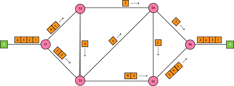
Approaches Of Packet Switching:
There are two approaches to Packet Switching:
Datagram Packet switching:
- It is a packet switching technology in which packet is known as a datagram, is considered as an independent entity. Each packet contains the information about the destination and switch uses this information to forward the packet to the correct destination.
- The packets are reassembled at the receiving end in correct order.
- In Datagram Packet Switching technique, the path is not fixed.
- Intermediate nodes take the routing decisions to forward the packets.
- Datagram Packet Switching is also known as connectionless switching.
Virtual Circuit Switching
- Virtual Circuit Switching is also known as connection-oriented switching.
- In the case of Virtual circuit switching, a preplanned route is established before the messages are sent.
- Call request and call accept packets are used to establish the connection between sender and receiver.
- In this case, the path is fixed for the duration of a logical connection.
Let's understand the concept of virtual circuit switching through a diagram:
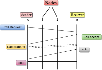
- In the above diagram, A and B are the sender and receiver respectively. 1 and 2 are the nodes.
- Call request and call accept packets are used to establish a connection between the sender and receiver.
- When a route is established, data will be transferred.
- After transmission of data, an acknowledgment signal is sent by the receiver that the message has been received.
- If the user wants to terminate the connection, a clear signal is sent for the termination.
Differences b/w Datagram approach and Virtual Circuit approach
Datagram approach | Virtual Circuit approach |
Node takes routing decisions to forward the packets. | Node does not take any routing decision. |
Congestion cannot occur as all the packets travel in different directions. | Congestion can occur when the node is busy, and it does not allow other packets to pass through. |
It is more flexible as all the packets are treated as an independent entity. | It is not very flexible. |
Advantages Of Packet Switching:
- Cost-effective: In packet switching technique, switching devices do not require massive secondary storage to store the packets, so cost is minimized to some extent. Therefore, we can say that the packet switching technique is a cost-effective technique.
- Reliable: If any node is busy, then the packets can be rerouted. This ensures that the Packet Switching technique provides reliable communication.
- Efficient: Packet Switching is an efficient technique. It does not require any established path prior to the transmission, and many users can use the same communication channel simultaneously, hence makes use of available bandwidth very efficiently.
Disadvantages Of Packet Switching:
- Packet Switching technique cannot be implemented in those applications that require low delay and high-quality services.
- The protocols used in a packet switching technique are very complex and requires high implementation cost.
- If the network is overloaded or corrupted, then it requires retransmission of lost packets. It can also lead to the loss of critical information if errors are nor recovered.
Key takeaways
- When a user accesses the internet or another computer network outside their immediate location, messages are sent through the network of transmission media. This technique of transferring the information from one computer network to another network is known as switching.
- Switching in a computer network is achieved by using switches. A switch is a small hardware device which is used to join multiple computers together with one local area network (LAN).
- Network switches operate at layer 2 (Data link layer) in the OSI model.
- Switching is transparent to the user and does not require any configuration in the home network.
- Switches are used to forward the packets based on MAC addresses.
- A Switch is used to transfer the data only to the device that has been addressed. It verifies the destination address to route the packet appropriately.
- It is operated in full duplex mode.
- Packet collision is minimum as it directly communicates between source and destination.
- It does not broadcast the message as it works with limited bandwidth.
What is IP?
An IP stands for internet protocol. An IP address is assigned to each device connected to a network. Each device uses an IP address for communication. It also behaves as an identifier as this address is used to identify the device on a network. It defines the technical format of the packets. Mainly, both the networks, i.e., IP and TCP, are combined together, so together, they are referred to as a TCP/IP. It creates a virtual connection between the source and the destination.
We can also define an IP address as a numeric address assigned to each device on a network. An IP address is assigned to each device so that the device on a network can be identified uniquely. To facilitate the routing of packets, TCP/IP protocol uses a 32-bit logical address known as IPv4(Internet Protocol version 4).
An IP address consists of two parts, i.e., the first one is a network address, and the other one is a host address.
There are two types of IP addresses:
- IPv4
- IPv6
What is IPv4?
IPv4 is a version 4 of IP. It is a current version and the most commonly used IP address. It is a 32-bit address written in four numbers separated by 'dot', i.e., periods. This address is unique for each device.
For example, 66.94.29.13
The above example represents the IP address in which each group of numbers separated by periods is called an Octet. Each number in an octet is in the range from 0-255. This address can produce 4,294,967,296 possible unique addresses.
In today's computer network world, computers do not understand the IP addresses in the standard numeric format as the computers understand the numbers in binary form only. The binary number can be either 1 or 0. The IPv4 consists of four sets, and these sets represent the octet. The bits in each octet represent a number.
Each bit in an octet can be either 1 or 0. If the bit the 1, then the number it represents will count, and if the bit is 0, then the number it represents does not count.
Representation of 8 Bit Octet

The above representation shows the structure of 8- bit octet.
Now, we will see how to obtain the binary representation of the above IP address, i.e., 66.94.29.13
Step 1: First, we find the binary number of 66.

To obtain 66, we put 1 under 64 and 2 as the sum of 64 and 2 is equal to 66 (64+2=66), and the remaining bits will be zero, as shown above. Therefore, the binary bit version of 66 is 01000010.
Step 2: Now, we calculate the binary number of 94.

To obtain 94, we put 1 under 64, 16, 8, 4, and 2 as the sum of these numbers is equal to 94, and the remaining bits will be zero. Therefore, the binary bit version of 94 is 01011110.
Step 3: The next number is 29.

To obtain 29, we put 1 under 16, 8, 4, and 1 as the sum of these numbers is equal to 29, and the remaining bits will be zero. Therefore, the binary bit version of 29 is 00011101.
Step 4: The last number is 13.

To obtain 13, we put 1 under 8, 4, and 1 as the sum of these numbers is equal to 13, and the remaining bits will be zero. Therefore, the binary bit version of 13 is 00001101.
Drawback of IPv4
Currently, the population of the world is 7.6 billion. Every user is having more than one device connected with the internet, and private companies also rely on the internet. As we know that IPv4 produces 4 billion addresses, which are not enough for each device connected to the internet on a planet. Although the various techniques were invented, such as variable- length mask, network address translation, port address translation, classes, inter-domain translation, to conserve the bandwidth of IP address and slow down the depletion of an IP address. In these techniques, public IP is converted into a private IP due to which the user having public IP can also use the internet. But still, this was not so efficient, so it gave rise to the development of the next generation of IP addresses, i.e., IPv6.
What is IPv6?
IPv4 produces 4 billion addresses, and the developers think that these addresses are enough, but they were wrong. IPv6 is the next generation of IP addresses. The main difference between IPv4 and IPv6 is the address size of IP addresses. The IPv4 is a 32-bit address, whereas IPv6 is a 128-bit hexadecimal address. IPv6 provides a large address space, and it contains a simple header as compared to IPv4.
It provides transition strategies that convert IPv4 into IPv6, and these strategies are as follows:
- Dual stacking: It allows us to have both the versions, i.e., IPv4 and IPv6, on the same device.
- Tunneling: In this approach, all the users have IPv6 communicates with an IPv4 network to reach IPv6.
- Network Address Translation: The translation allows the communication between the hosts having a different version of IP.
This hexadecimal address contains both numbers and alphabets. Due to the usage of both the numbers and alphabets, IPv6 is capable of producing over 340 undecillion (3.4*1038) addresses.
IPv6 is a 128-bit hexadecimal address made up of 8 sets of 16 bits each, and these 8 sets are separated by a colon. In IPv6, each hexadecimal character represents 4 bits. So, we need to convert 4 bits to a hexadecimal number at a time
Address format
The address format of IPv4:

The address format of IPv6:

The above diagram shows the address format of IPv4 and IPv6. An IPv4 is a 32-bit decimal address. It contains 4 octets or fields separated by 'dot', and each field is 8-bit in size. The number that each field contains should be in the range of 0-255. Whereas an IPv6 is a 128-bit hexadecimal address. It contains 8 fields separated by a colon, and each field is 16-bit in size.
Differences between IPv4 and IPv6
| Ipv4 | Ipv6 |
Address length | IPv4 is a 32-bit address. | IPv6 is a 128-bit address. |
Fields | IPv4 is a numeric address that consists of 4 fields which are separated by dot (.). | IPv6 is an alphanumeric address that consists of 8 fields, which are separated by colon. |
Classes | IPv4 has 5 different classes of IP address that includes Class A, Class B, Class C, Class D, and Class E. | IPv6 does not contain classes of IP addresses. |
Number of IP address | IPv4 has a limited number of IP addresses. | IPv6 has a large number of IP addresses. |
VLSM | It supports VLSM (Virtual Length Subnet Mask). Here, VLSM means that Ipv4 converts IP addresses into a subnet of different sizes. | It does not support VLSM. |
Address configuration | It supports manual and DHCP configuration. | It supports manual, DHCP, auto-configuration, and renumbering. |
Address space | It generates 4 billion unique addresses | It generates 340 undecillion unique addresses. |
End-to-end connection integrity | In IPv4, end-to-end connection integrity is unachievable. | In the case of IPv6, end-to-end connection integrity is achievable. |
Security features | In IPv4, security depends on the application. This IP address is not developed in keeping the security feature in mind. | In IPv6, IPSEC is developed for security purposes. |
Address representation | In IPv4, the IP address is represented in decimal. | In IPv6, the representation of the IP address in hexadecimal. |
Fragmentation | Fragmentation is done by the senders and the forwarding routers. | Fragmentation is done by the senders only. |
Packet flow identification | It does not provide any mechanism for packet flow identification. | It uses flow label field in the header for the packet flow identification. |
Checksum field | The checksum field is available in IPv4. | The checksum field is not available in IPv6. |
Transmission scheme | IPv4 is broadcasting. | On the other hand, IPv6 is multicasting, which provides efficient network operations. |
Encryption and Authentication | It does not provide encryption and authentication. | It provides encryption and authentication. |
Number of octets | It consists of 4 octets. | It consists of 8 fields, and each field contains 2 octets. Therefore, the total number of octets in IPv6 is 16. |
Key takeaways
- An IP stands for internet protocol. An IP address is assigned to each device connected to a network. Each device uses an IP address for communication. It also behaves as an identifier as this address is used to identify the device on a network. It defines the technical format of the packets. Mainly, both the networks, i.e., IP and TCP, are combined together, so together, they are referred to as a TCP/IP. It creates a virtual connection between the source and the destination.
- We can also define an IP address as a numeric address assigned to each device on a network. An IP address is assigned to each device so that the device on a network can be identified uniquely. To facilitate the routing of packets, TCP/IP protocol uses a 32-bit logical address known as IPv4(Internet Protocol version 4).
- An IP address consists of two parts, i.e., the first one is a network address, and the other one is a host address.
- There are two types of IP addresses:
IPv4
IPv6
Address Resolution Protocol (ARP) and its types
Address Resolution Protocol (ARP) is a communication protocol used to find the MAC (Media Access Control) address of a device from its IP address. This protocol is used when a device wants to communicate with another device on a Local Area Network or Ethernet.
Types of ARP
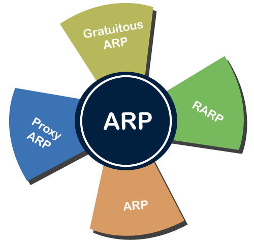
There are four types of Address Resolution Protocol, which is given below:
- Proxy ARP
- Gratuitous ARP
- Reverse ARP (RARP)
- Inverse ARP
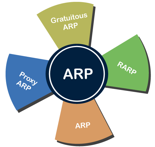
Fig 8 – ARP
Proxy ARP - Proxy ARP is a method through which a Layer 3 devices may respond to ARP requests for a target that is in a different network from the sender. The Proxy ARP configured router responds to the ARP and map the MAC address of the router with the target IP address and fool the sender that it is reached at its destination.
At the backend, the proxy router sends its packets to the appropriate destination because the packets contain the necessary information.
Example - If Host A wants to transmit data to Host B, which is on the different network, then Host A sends an ARP request message to receive a MAC address for Host B. The router responds to Host A with its own MAC address pretend itself as a destination. When the data is transmitted to the destination by Host A, it will send to the gateway so that it sends to Host B. This is known as proxy ARP.
Gratuitous ARP - Gratuitous ARP is an ARP request of the host that helps to identify the duplicate IP address. It is a broadcast request for the IP address of the router. If an ARP request is sent by a switch or router to get its IP address and no ARP responses are received, so all other nodes cannot use the IP address allocated to that switch or router. Yet if a router or switch sends an ARP request for its IP address and receives an ARP response, another node uses the IP address allocated to the switch or router.
There are some primary use cases of gratuitous ARP that are given below:
- The gratuitous ARP is used to update the ARP table of other devices.
- It also checks whether the host is using the original IP address or a duplicate one.
Reverse ARP (RARP) - It is a networking protocol used by the client system in a local area network (LAN) to request its IPv4 address from the ARP gateway router table. A table is created by the network administrator in the gateway-router that is used to find out the MAC address to the corresponding IP address.
When a new system is set up or any machine that has no memory to store the IP address, then the user has to find the IP address of the device. The device sends a RARP broadcast packet, including its own MAC address in the address field of both the sender and the receiver hardware. A host installed inside of the local network called the RARP-server is prepared to respond to such type of broadcast packet. The RARP server is then trying to locate a mapping table entry in the IP to MAC address. If any entry matches the item in the table, then the RARP server sends the response packet along with the IP address to the requesting computer.
Inverse ARP (InARP) - Inverse ARP is inverse of the ARP, and it is used to find the IP addresses of the nodes from the data link layer addresses. These are mainly used for the frame relays, and ATM networks, where Layer 2 virtual circuit addressing are often acquired from Layer 2 signaling. When using these virtual circuits, the relevant Layer 3 addresses are available.
ARP conversions Layer 3 addresses to Layer 2 addresses. However, its opposite address can be defined by InARP. The InARP has a similar packet format as ARP, but operational codes are different.
Bootstrap Protocol (BOOTP)
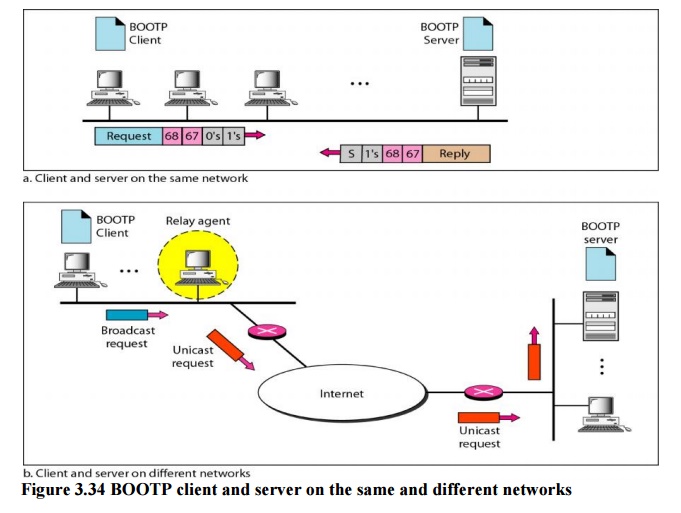
Fig 9 – BOOTP client and server on the same and different networks
The Bootstrap Protocol (BOOTP) is a client/server protocol designed to provide physical address to logical address mapping.
BOOTP
The Bootstrap Protocol (BOOTP) is a client/server protocol designed to provide physical address to logical address mapping. BOOTP is an application layer protocol. The administrator may put the client and the server on the same network or on different networks
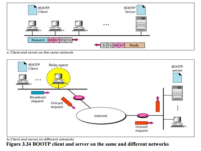
Fig 10 – BOOTP client and server on the same and different networks
One of the advantages of BOOTP over RARP is that the client and server are application-layer processes. As in other application-layer processes, a client can be in one network and the server in another, separated by several other networks. However, there is one problem that must be solved. The BOOTP request is broadcast because the client does not know the IP address of the server. A broadcast IP datagram cannot pass through any router. To solve the problem, there is a need for an intermediary. One of the hosts (or a router that can be configured to operate at the application layer) can be used as a relay. The host in this case is called a relay agent. The relay agent knows the unicast address of a BOOTP server. When it receives this type of packet, it encapsulates the message in a unicast datagram and sends the request to the BOOTP server. The packet, carrying a unicast destination address, is routed by any router and reaches the BOOTP server. The BOOTP server knows the message comes from a relay agent because one of the fields in the request message defines the IP address of the relay agent. The relay agent, after receiving the reply, sends it to the BOOTP client.
Dynamic Host Configuration Protocol
Dynamic Host Configuration Protocol (DHCP) is a network management protocol used to dynamically assign an IP address to nay device, or node, on a network so they can communicate using IP (Internet Protocol). DHCP automates and centrally manages these configurations. There is no need to manually assign IP addresses to new devices. Therefore, there is no requirement for any user configuration to connect to a DHCP based network.
DHCP can be implemented on local networks as well as large enterprise networks. DHCP is the default protocol used by the most routers and networking equipment. DHCP is also called RFC (Request for comments) 2131.
DHCP does the following:
- DHCP manages the provision of all the nodes or devices added or dropped from the network.
- DHCP maintains the unique IP address of the host using a DHCP server.
- It sends a request to the DHCP server whenever a client/node/device, which is configured to work with DHCP, connects to a network. The server acknowledges by providing an IP address to the client/node/device.
DHCP is also used to configure the proper subnet mask, default gateway and DNS server information on the node or device.
There are many versions of DCHP are available for use in IPV4 (Internet Protocol Version 4) and IPV6 (Internet Protocol Version 6).
How DHCP works
DHCP runs at the application layer of the TCP/IP protocol stack to dynamically assign IP addresses to DHCP clients/nodes and to allocate TCP/IP configuration information to the DHCP clients. Information includes subnet mask information, default gateway, IP addresses and domain name system addresses.
DHCP is based on client-server protocol in which servers manage a pool of unique IP addresses, as well as information about client configuration parameters, and assign addresses out of those address pools.
The DHCP lease process works as follows:
- First of all, a client (network device) must be connected to the internet.
- DHCP clients request an IP address. Typically, client broadcasts a query for this information.
- DHCP server responds to the client request by providing IP server address and other configuration information. This configuration information also includes time period, called a lease, for which the allocation is valid.
- When refreshing an assignment, a DHCP clients request the same parameters, but the DHCP server may assign a new IP address. This is based on the policies set by the administrator.
Components of DHCP
When working with DHCP, it is important to understand all of the components. Following are the list of components:
- DHCP Server: DHCP server is a networked device running the DCHP service that holds IP addresses and related configuration information. This is typically a server or a router but could be anything that acts as a host, such as an SD-WAN appliance.
- DHCP client: DHCP client is the endpoint that receives configuration information from a DHCP server. This can be any device like computer, laptop, IoT endpoint or anything else that requires connectivity to the network. Most of the devices are configured to receive DHCP information by default.
- IP address pool: IP address pool is the range of addresses that are available to DHCP clients. IP addresses are typically handed out sequentially from lowest to the highest.
- Subnet: Subnet is the partitioned segments of the IP networks. Subnet is used to keep networks manageable.
- Lease: Lease is the length of time for which a DHCP client holds the IP address information. When a lease expires, the client has to renew it.
- DHCP relay: A host or router that listens for client messages being broadcast on that network and then forwards them to a configured server. The server then sends responses back to the relay agent that passes them along to the client. DHCP relay can be used to centralize DHCP servers instead of having a server on each subnet.
Benefits of DHCP
There are following benefits of DHCP:
Centralized administration of IP configuration: DHCP IP configuration information can be stored in a single location and enables that administrator to centrally manage all IP address configuration information.
Dynamic host configuration: DHCP automates the host configuration process and eliminates the need to manually configure individual host. When TCP/IP (Transmission control protocol/Internet protocol) is first deployed or when IP infrastructure changes are required.
Seamless IP host configuration: The use of DHCP ensures that DHCP clients get accurate and timely IP configuration IP configuration parameter such as IP address, subnet mask, default gateway, IP address of DND server and so on without user intervention.
Flexibility and scalability: Using DHCP gives the administrator increased flexibility, allowing the administrator to move easily change IP configuration when the infrastructure changes.
Key takeaways
- Address Resolution Protocol (ARP) is a communication protocol used to find the MAC (Media Access Control) address of a device from its IP address. This protocol is used when a device wants to communicate with another device on a Local Area Network or Ethernet.
- There are four types of Address Resolution Protocol, which is given below:
- Proxy ARP
- Gratuitous ARP
- Reverse ARP (RARP)
- Inverse ARP
When a device has multiple paths to reach a destination, it always selects one path by preferring it over others. This selection process is termed as Routing. Routing is done by special network devices called routers or it can be done by means of software processes. The software based routers have limited functionality and limited scope.
A router is always configured with some default route. A default route tells the router where to forward a packet if there is no route found for specific destination. In case there are multiple path existing to reach the same destination, router can make decision based on the following information:
- Hop Count
- Bandwidth
- Metric
- Prefix-length
- Delay
Routes can be statically configured or dynamically learnt. One route can be configured to be preferred over others.
Unicast routing
Most of the traffic on the internet and intranets known as unicast data or unicast traffic is sent with specified destination. Routing unicast data over the internet is called unicast routing. It is the simplest form of routing because the destination is already known. Hence the router just has to look up the routing table and forward the packet to next hop.
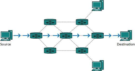
Fig 10 – Unicast routing
Broadcast routing
By default, the broadcast packets are not routed and forwarded by the routers on any network. Routers create broadcast domains. But it can be configured to forward broadcasts in some special cases. A broadcast message is destined to all network devices.
Broadcast routing can be done in two ways (algorithm):
- A router creates a data packet and then sends it to each host one by one. In this case, the router creates multiple copies of single data packet with different destination addresses. All packets are sent as unicast but because they are sent to all, it simulates as if router is broadcasting.
This method consumes lots of bandwidth and router must destination address of each node.
- Secondly, when router receives a packet that is to be broadcasted, it simply floods those packets out of all interfaces. All routers are configured in the same way.
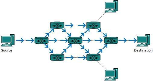
Fig 11 – Broadcast routing
This method is easy on router's CPU but may cause the problem of duplicate packets received from peer routers.
Reverse path forwarding is a technique, in which router knows in advance about its predecessor from where it should receive broadcast. This technique is used to detect and discard duplicates.
Multicast Routing
Multicast routing is special case of broadcast routing with significance difference and challenges. In broadcast routing, packets are sent to all nodes even if they do not want it. But in Multicast routing, the data is sent to only nodes which wants to receive the packets.
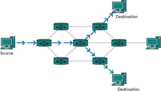
Fig 12 – Multicast routing
The router must know that there are nodes, which wish to receive multicast packets (or stream) then only it should forward. Multicast routing works spanning tree protocol to avoid looping.
Multicast routing also uses reverse path Forwarding technique, to detect and discard duplicates and loops.
Anycast Routing
Anycast packet forwarding is a mechanism where multiple hosts can have same logical address. When a packet destined to this logical address is received, it is sent to the host which is nearest in routing topology.
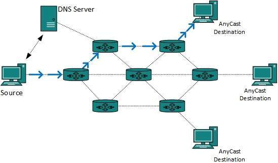
Fig 13 – Anycast routing
Anycast routing is done with help of DNS server. Whenever an Anycast packet is received it is enquired with DNS to where to send it. DNS provides the IP address which is the nearest IP configured on it.
Unicast Routing Protocols
There are two kinds of routing protocols available to route unicast packets:
- Distance Vector Routing Protocol
Distance Vector is simple routing protocol which takes routing decision on the number of hops between source and destination. A route with less number of hops is considered as the best route. Every router advertises its set best routes to other routers. Ultimately, all routers build up their network topology based on the advertisements of their peer routers,
For example Routing Information Protocol (RIP).
- Link State Routing Protocol
Link State protocol is slightly complicated protocol than Distance Vector. It takes into account the states of links of all the routers in a network. This technique helps routes build a common graph of the entire network. All routers then calculate their best path for routing purposes.for example, Open Shortest Path First (OSPF) and Intermediate System to Intermediate System (ISIS).
Multicast Routing Protocols
Unicast routing protocols use graphs while Multicast routing protocols use trees, i.e. spanning tree to avoid loops. The optimal tree is called shortest path spanning tree.
- DVMRP - Distance Vector Multicast Routing Protocol
- MOSPF - Multicast Open Shortest Path First
- CBT - Core Based Tree
- PIM - Protocol independent Multicast
Protocol Independent Multicast is commonly used now. It has two flavors:
- PIM Dense Mode
This mode uses source-based trees. It is used in dense environment such as LAN.
- PIM Sparse Mode
This mode uses shared trees. It is used in sparse environment such as WAN.
Routing Algorithms
The routing algorithms are as follows:
Flooding
Flooding is simplest method packet forwarding. When a packet is received, the routers send it to all the interfaces except the one on which it was received. This creates too much burden on the network and lots of duplicate packets wandering in the network.
Time to Live (TTL) can be used to avoid infinite looping of packets. There exists another approach for flooding, which is called Selective Flooding to reduce the overhead on the network. In this method, the router does not flood out on all the interfaces, but selective ones.
Shortest Path
Routing decision in networks, are mostly taken on the basis of cost between source and destination. Hop count plays major role here. Shortest path is a technique which uses various algorithms to decide a path with minimum number of hops.
Common shortest path algorithms are:
- Dijkstra's algorithm
- Bellman Ford algorithm
- Floyd Warshall algorithm
Routing
- A Router is a process of selecting path along which the data can be transferred from source to the destination. Routing is performed by a special device known as a router.
- A Router works at the network layer in the OSI model and internet layer in TCP/IP model
- A router is a networking device that forwards the packet based on the information available in the packet header and forwarding table.
- The routing algorithms are used for routing the packets. The routing algorithm is nothing but a software responsible for deciding the optimal path through which packet can be transmitted.
- The routing protocols use the metric to determine the best path for the packet delivery. The metric is the standard of measurement such as hop count, bandwidth, delay, current load on the path, etc. used by the routing algorithm to determine the optimal path to the destination.
- The routing algorithm initializes and maintains the routing table for the process of path determination.
Routing Metrics and Costs
Routing metrics and costs are used for determining the best route to the destination. The factors used by the protocols to determine the shortest path, these factors are known as a metric.
Metrics are the network variables used to determine the best route to the destination. For some protocols use the static metrics means that their value cannot be changed and for some other routing protocols use the dynamic metrics means that their value can be assigned by the system administrator.
The most common metric values are given below:
- Hop count: Hop count is defined as a metric that specifies the number of passes through internetworking devices such as a router, a packet must travel in a route to move from source to the destination. If the routing protocol considers the hop as a primary metric value, then the path with the least hop count will be considered as the best path to move from source to the destination.
- Delay: It is a time taken by the router to process, queue and transmit a datagram to an interface. The protocols use this metric to determine the delay values for all the links along the path end-to-end. The path having the lowest delay value will be considered as the best path.
- Bandwidth: The capacity of the link is known as a bandwidth of the link. The bandwidth is measured in terms of bits per second. The link that has a higher transfer rate like gigabit is preferred over the link that has the lower capacity like 56 kb. The protocol will determine the bandwidth capacity for all the links along the path, and the overall higher bandwidth will be considered as the best route.
- Load: Load refers to the degree to which the network resource such as a router or network link is busy. A Load can be calculated in a variety of ways such as CPU utilization, packets processed per second. If the traffic increases, then the load value will also be increased. The load value changes with respect to the change in the traffic.
- Reliability: Reliability is a metric factor may be composed of a fixed value. It depends on the network links, and its value is measured dynamically. Some networks go down more often than others. After network failure, some network links repaired more easily than other network links. Any reliability factor can be considered for the assignment of reliability ratings, which are generally numeric values assigned by the system administrator.
Types of Routing
Routing can be classified into three categories:
- Static Routing
- Default Routing
- Dynamic Routing
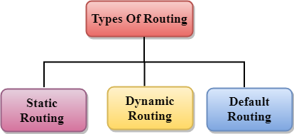
Fig 14 – Types of routing
Static Routing
- Static Routing is also known as Nonadaptive Routing.
- It is a technique in which the administrator manually adds the routes in a routing table.
- A Router can send the packets for the destination along the route defined by the administrator.
- In this technique, routing decisions are not made based on the condition or topology of the networks
Advantages Of Static Routing
Following are the advantages of Static Routing:
- No Overhead: It has ho overhead on the CPU usage of the router. Therefore, the cheaper router can be used to obtain static routing.
- Bandwidth: It has not bandwidth usage between the routers.
- Security: It provides security as the system administrator is allowed only to have control over the routing to a particular network.
Disadvantages of Static Routing:
Following are the disadvantages of Static Routing:
- For a large network, it becomes a very difficult task to add each route manually to the routing table.
- The system administrator should have a good knowledge of a topology as he has to add each route manually.
Default Routing
- Default Routing is a technique in which a router is configured to send all the packets to the same hop device, and it doesn't matter whether it belongs to a particular network or not. A Packet is transmitted to the device for which it is configured in default routing.
- Default Routing is used when networks deal with the single exit point.
- It is also useful when the bulk of transmission networks have to transmit the data to the same hp device.
- When a specific route is mentioned in the routing table, the router will choose the specific route rather than the default route. The default route is chosen only when a specific route is not mentioned in the routing table.
Dynamic Routing
- It is also known as Adaptive Routing.
- It is a technique in which a router adds a new route in the routing table for each packet in response to the changes in the condition or topology of the network.
- Dynamic protocols are used to discover the new routes to reach the destination.
- In Dynamic Routing, RIP and OSPF are the protocols used to discover the new routes.
- If any route goes down, then the automatic adjustment will be made to reach the destination.
The Dynamic protocol should have the following features:
- All the routers must have the same dynamic routing protocol in order to exchange the routes.
- If the router discovers any change in the condition or topology, then router broadcast this information to all other routers.
Advantages of Dynamic Routing:
- It is easier to configure.
- It is more effective in selecting the best route in response to the changes in the condition or topology.
Disadvantages of Dynamic Routing:
- It is more expensive in terms of CPU and bandwidth usage.
- It is less secure as compared to default and static routing.
Routing algorithm
- In order to transfer the packets from source to the destination, the network layer must determine the best route through which packets can be transmitted.
- Whether the network layer provides datagram service or virtual circuit service, the main job of the network layer is to provide the best route. The routing protocol provides this job.
- The routing protocol is a routing algorithm that provides the best path from the source to the destination. The best path is the path that has the "least-cost path" from source to the destination.
- Routing is the process of forwarding the packets from source to the destination but the best route to send the packets is determined by the routing algorithm.
Classification of a Routing algorithm
The Routing algorithm is divided into two categories:
- Adaptive Routing algorithm
- Non-adaptive Routing algorithm
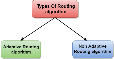
Fig 15 – Types of routing algorithm
Adaptive Routing algorithm
- An adaptive routing algorithm is also known as dynamic routing algorithm.
- This algorithm makes the routing decisions based on the topology and network traffic.
- The main parameters related to this algorithm are hop count, distance and estimated transit time.
An adaptive routing algorithm can be classified into three parts:
- Centralized algorithm: It is also known as global routing algorithm as it computes the least-cost path between source and destination by using complete and global knowledge about the network. This algorithm takes the connectivity between the nodes and link cost as input, and this information is obtained before actually performing any calculation. Link state algorithm is referred to as a centralized algorithm since it is aware of the cost of each link in the network.
- Isolation algorithm: It is an algorithm that obtains the routing information by using local information rather than gathering information from other nodes.
- Distributed algorithm: It is also known as decentralized algorithm as it computes the least-cost path between source and destination in an iterative and distributed manner. In the decentralized algorithm, no node has the knowledge about the cost of all the network links. In the beginning, a node contains the information only about its own directly attached links and through an iterative process of calculation computes the least-cost path to the destination. A Distance vector algorithm is a decentralized algorithm as it never knows the complete path from source to the destination, instead it knows the direction through which the packet is to be forwarded along with the least cost path.
Non-Adaptive Routing algorithm
- Non Adaptive routing algorithm is also known as a static routing algorithm.
- When booting up the network, the routing information stores to the routers.
- Non Adaptive routing algorithms do not take the routing decision based on the network topology or network traffic.
The Non-Adaptive Routing algorithm is of two types:
Flooding: In case of flooding, every incoming packet is sent to all the outgoing links except the one from it has been reached. The disadvantage of flooding is that node may contain several copies of a particular packet.
Random walks: In case of random walks, a packet sent by the node to one of its neighbors randomly. An advantage of using random walks is that it uses the alternative routes very efficiently.
Differences b/w Adaptive and Non-Adaptive Routing Algorithm
Basis Of Comparison | Adaptive Routing algorithm | Non-Adaptive Routing algorithm |
Define | Adaptive Routing algorithm is an algorithm that constructs the routing table based on the network conditions. | The Non-Adaptive Routing algorithm is an algorithm that constructs the static table to determine which node to send the packet. |
Usage | Adaptive routing algorithm is used by dynamic routing. | The Non-Adaptive Routing algorithm is used by static routing. |
Routing decision | Routing decisions are made based on topology and network traffic. | Routing decisions are the static tables. |
Categorization | The types of adaptive routing algorithm, are Centralized, isolation and distributed algorithm. | The types of Non Adaptive routing algorithm are flooding and random walks. |
Complexity | Adaptive Routing algorithms are more complex. | Non-Adaptive Routing algorithms are simple. |
Key takeaways
- When a device has multiple paths to reach a destination, it always selects one path by preferring it over others. This selection process is termed as Routing. Routing is done by special network devices called routers or it can be done by means of software processes.The software based routers have limited functionality and limited scope.
- A router is always configured with some default route. A default route tells the router where to forward a packet if there is no route found for specific destination. In case there are multiple path existing to reach the same destination, router can make decision based on the following information:
- Hop Count
- Bandwidth
- Metric
- Prefix-length
- Delay
3. Routes can be statically configured or dynamically learnt. One route can be configured to be preferred over others.
References:
1. Computer Networks, 8th Edition, Andrew S. Tanenbaum, Pearson New International Edition.
2. Internetworking with TCP/IP, Volume 1, 6th Edition Douglas Comer, Prentice Hall of India.
3. TCP/IP Illustrated, Volume 1, W. Richard Stevens, Addison-Wesley, United States of America.