Module 1
Network Theorems
Superposition theorem states that in any linear, active, bilateral network having more than one source, the response across any element is the sum of the responses obtained from each source considered separately and all other sources are replaced by their internal resistance. The superposition theorem is used to solve the network where two or more sources are present and connected.
If a number of voltage or current sources are acting in a linear network, the resulting current in any branch is the algebraic sum of all the currents that would be produced in it when each source acts alone while all the other independent sources are replaced by their internal resistances.
Example:
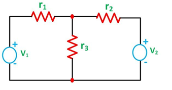
The circuit diagram is shown below consists of two voltage sources V1 and V2.
First, take the source V1 alone and short circuit the V2 source as shown in the diagram below:
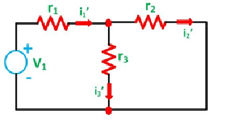
The value of current flowing in each branch, that is i1’, i2’ and i3’ is calculated by the following equations.
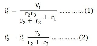
The difference between the two equations gives the value of the current i3’
Next, activate the voltage source V2 and deactivating the voltage source V1 by short-circuiting it, find the various currents, that is i1’’, i2’’, i3’’ flowing in the circuit diagram shown below:
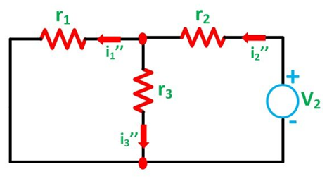
Here,

And the value of the current i3’’ will be calculated by the equation shown below:
As per the superposition theorem, the value of current i1, i2, i3 is now calculated as:
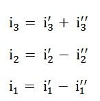
The direction of the current should be taken care of while finding the current in the various branches.
The steps for solving Superposition Theorem
Considering the circuit diagramA, let us see the various steps to solve the superposition theorem:
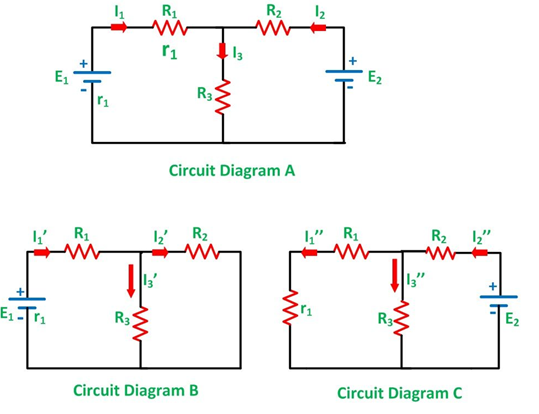
Step 1 – Take only one independent source of voltage or current and deactivate the other sources.
Step 2 – In the circuit diagram B, consider source E1 and replace the other source E2 by its internal resistance. If its internal resistance is not given, then it is taken as zero and the source is short-circuited.
Step 3 – If there is a voltage source than short circuit it and if there is a current source then just open circuit it.
Step 4 – Thus, by activating one source and deactivating the other source find the current in each branch of the network. Taking the above example find the current I1’, I2’and I3’.
Step 5 – Now consider the other source E2 and replace the source E1 by its internal resistance r1 as shown in the circuit diagram C.
Step 6 – Determine the current in various sections, I1’’, I2’’ and I3’’.
Step 7 – Now to determine the net branch current utilizing the superposition theorem, add the currents obtained from each individual source for each branch.
Step 8 – If the current obtained by each branch is in the same direction then add them and if it is in the opposite direction, subtract them to obtain the net current in each branch.
The actual flow of current in the circuit C will be given by the equations shown below: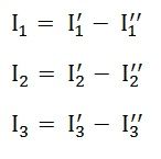
Problem:
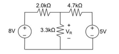
Using Superposition theorem determine the voltage drop and current across the resistor 3.3K as shown in figure below
Step 1:
Remove 8V power supply from the original circuit such that the new circuit becomes as the following and measure the voltage across resistor.
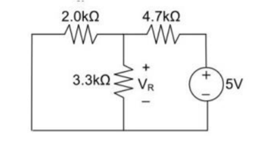
Here 3.3 K and 2K are in parallel therefore the resultant resistance will be 1.245K
Using voltage divider rule across 1.245K will be
V1 =[1.245/(1.245+4.7)] * 5 = 1.047V
Step 2:
Remove the 5V power supply from the original circuit such that the new circuit becomes the following and then measure the voltage across resistor.
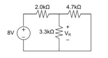
Here 3.3K and 4.7K are in parallel therefore the resultant resistance will be 1.938K. Using voltage divider rule voltage across 1.938K will be
V2 =[1.938(1.938+2)] *8 = 3.9377V
Therefore, voltage drop across 3.3K resistor is V1+V2 = 1.047 + 3.9377 = 4.9847V
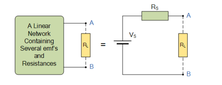
Thevenin’s Theorem states that “Any linear circuit containing several voltages and resistances can be replaced by just one single voltage in series with a single resistance connected across the load”.
To simplify any electrical circuit, to an equivalent two-terminal circuit with just a single constant voltage source in series with a resistance (or impedance) connected to a load as shown below.
Consider the circuit as shown in figure:
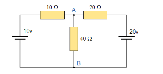
In order to analyse the circuit initially remove the 40Ω load resistor connected across the terminals AB and remove any internal resistance associated with the voltage source.
This is done by shorting out all the voltage sources connected to the circuit. Therefore v=0 or open circuit any connected current sources making i=0.
This because we want to make an ideal voltage source or ideal current source making for circuit analysis.
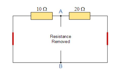
The value of the equivalent resistance, Rs is found by calculating the total resistance looking back from the terminals A and B with all the voltage sources shorted.
10 Ω resistor in parallel with 20Ω resistor
RT = R1 x R2/ R1 + R2 = 20 x 10 / 20 + 10 = 6.67 Ω
Find the equivalent voltage
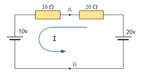
To reconnect the two voltages back into the circuit Vs=VAB the current flowing around the loop is calculated as:
I = V/R = 20 V – 10V / 20 Ω + 10 Ω = 0.33 Amps.
The current is common to both resistors so the voltage drop across the 20Ω resistor or the 10Ω resistor is calculated as:
VAB = 20 –( 20 Ω x 0.33 amps) = 13.33 volts
VAB = 10 + (10 Ω x 0.33 amps) = 13.33 volts
The Thevenin’s Equivalent circuit is a series resistance of 6.67Ω and the voltage source of 13.33 V.
If 40Ω resistor is connected back to the circuit, we get
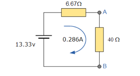
And from this the current flowing around the circuit is given as:
I = V/R = 13.33/6.67 + 40 = 0.286 amps.
Problem:
For the circuit as shown in figure find the current through RL = R2 = 1Ω resistor (Ia-b) branch using Thevenin’s theorem. Find the voltage across the current source.
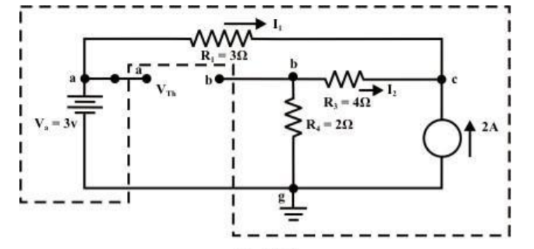
Step 1: Disconnect the load resistance and reconnect the circuit.
Step 2: Apply any method to calculate Vth
At node C
2 + I1 + I2 =0
2 + (3 -Vc)/3 + (0-Vc/6) -- Vc = 6V
The currents I1 and I2 are computed by the following expressions:
I1 = Va -Vc/3 = 3-6/3 = -1A (I1 is flowing from c to a)
I2 = 0 – Vc/6 = -6/6 = -1A (I2 is flowing from c to a)
Step-3:
Redraw the circuit indicating the direction of currents in different branches. One can find the Thevenin’s voltage VTh using KVL around the closed path ‘gabg’
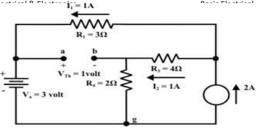
VTh = Vag − Vbg = 3 − 2 =1volt
Step 4:
Replace all sources by their internal resistances. In this problem, voltage source has an internal resistance zero (0) (ideal voltage source) and it is short-circuited with a wire.
On the other hand, the current source has an infinite internal resistance (ideal current source) and it is open-circuited (just remove the current source).
Thevenin’s resistance RTh of the fixed part of the circuit can be computed by looking at the load terminals ‘a’- ‘b’
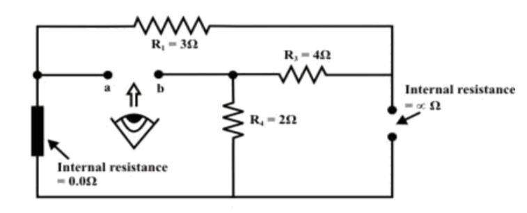
RTh = ( R1 + R3 ) & R4 = ( 3 + 4 )&2 = 1.555Ω
Step-5: Place RTh in series with VTh to form the Thevenin’s equivalent circuit. Reconnect the original load resistance RL = R2 = 1 Ω to the Thevenin’s equivalent circuit .
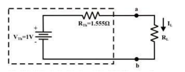
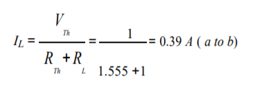
Step-6: The circuit is redrawn to indicate different branch currents. Referring to one can calculate the voltage Vbg and voltage across the current source (Vcg ) using the following equations.
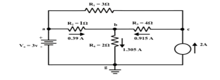
Vbg = Vag − Vab = 3 − 1 × 0.39 =2.61 volt.
Ibg = 2.61 2 = 1.305 A;
Icb = 1.305 − 0.39 = 0.915 A
Vcg = 4 × 0.915 + 2 ×1.305 =6.27 volt.
For the circuit shown in figure, find the current IL through 6 Ω resistor using Thevenin’s theorem.

Step-1:
Disconnect 6 Ω from the terminals ‘a’ and ‘b’ and the corresponding circuit diagram. Consider point ‘g’ as ground potential and other voltages are measured with respect to this point.
Step-2:
Apply any suitable method to find the Thevenin’s voltage (VTh )
KVL is applied around the closed path ‘gcag’ to compute Thevenin’s voltage.
42 – 8I – 4I -30 = 0 ; I = 1A
Vag = 30+4 = 34 volt
Vbg = 2 x 3 = 6 volt
Vth = Vab = Vag – Vbg = 34 -6 = 28 volt
Step-3:
Thevenin’s resistance RTh can be found by replacing all sources by their internal resistances all voltage sources are short-circuited and current sources are just removed or open circuited.
Rth = (8 x4) / 12 + 2 = 14/3 = 4.666Ω
Step-4:
Thevenin’s equivalent circuit is now equivalently represents the original circuit

IL = Vth / Rth + RL = 28 / 4.666 +6 = 2.625 A
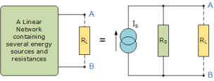
Norton’s Theorem states that “Any linear circuit containing several energy sources and resistances can be replaced by a single Constant Current generator in parallel with a Single Resistor”.
To find the Norton’s equivalent remove the centre 40Ω load resistor and short out the terminals A and B to give us the following circuit.
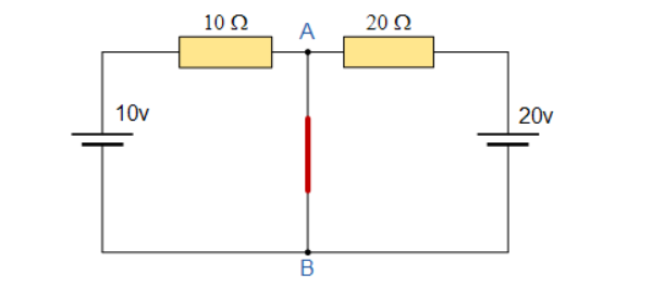
When the terminals A and B are shorted together the two resistors are connected in parallel across their two respective voltage sources and the currents flowing through each resistor as well as the total short circuit current can now be calculated as:
With A-B shorted out
I1 = 10 / 10 = 1A I2 = 20/20 = 1A , Therefore I short-circuit = I1 + I2 = 2 amps
If we short-out the two voltage sources and open circuit terminals A and B, the two resistors are connected in parallel. The value of the internal resistor Rs is found by calculating the total resistance at the terminals A and B giving us the following circuit.
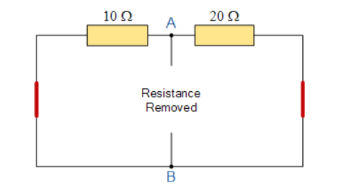
The equivalent resistance is given by 10Ω resistor in parallel with 20 Ω resistor
RT = R1 x R2 / R1 + R2 = 20 x 10 / 20 + 10 = 6.67 Ω.
Norton’s equivalent circuit.
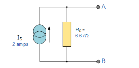
To solve with the original 40Ω load resistor connected across terminals A and B as shown below.
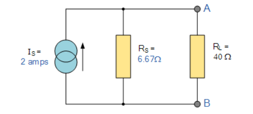
The two resistors are connected in parallel across the terminals A and B which gives us a total resistance of:
RT = R1 x R2 / R1 + R2 = 6.67 x 40 / 6.67 + 40 = 5.72 Ω.
The voltage across the terminals A and B with the load resistor connected is given as:
Va-b = I x R = 2 x 5.72 = 11.44V
Then the current flowing in the 40 Ω load resistor can be found as :
I = V / R = 11.44 / 40 = 0.286 amps.
Problem:
Find RN, IN, the current flowing through and load Voltage across the load resistor in fig (1) by using Norton’s Theorem.

Step 1:
Short the 1.5 Ω load resistor.
Step 2:
Norton current.
Short AB terminals to obtain IN . The total resistance of the circuit is
2Ω + (6Ω || 3Ω)
RT = 4 Ω
IT = V / RT = 12/ 4 = 3 A
IN = 3 A x [ 6Ω / 3 + 6 )] = 2A
IN = 2A
Step 3:
Open current sources, Short Voltage sources and Open Load resistor.
Step 4:
Calculate Norton Resistance (RN)
Reduce 12V dc source. 3Ω resistor is in series with combination of 6Ω and 2Ω resistor
3Ω + (6Ω||2Ω)
3Ω + 1.5 Ω = 4.5 Ω; RN = 4.5 Ω
Step 5:
Connect RN in parallel with current source IN and the load resistor.
Step 6:
The load current through Load resistor
IL = IN x [ RN /(RN + RL)
=2 A x ( 4.5 / 4.5 + 1.5 K) = 1.5 A
IL = 1.5 A
The voltage across load resistor
VL = IL x RL
= 1.5 x 1.5
VL = 2.25 V
Maximum power transfer theorem states that AC voltage source will deliver maximum power to the variable complex load only when the load impedance is equal to the complex conjugate of source impedance.
Proof:
Replace any two terminal linear network or circuit to the left side of variable load resistor having resistance of RL ohms with a Thevenin’s equivalent circuit. We know that Thevenin’s equivalent circuit resembles a practical voltage source.
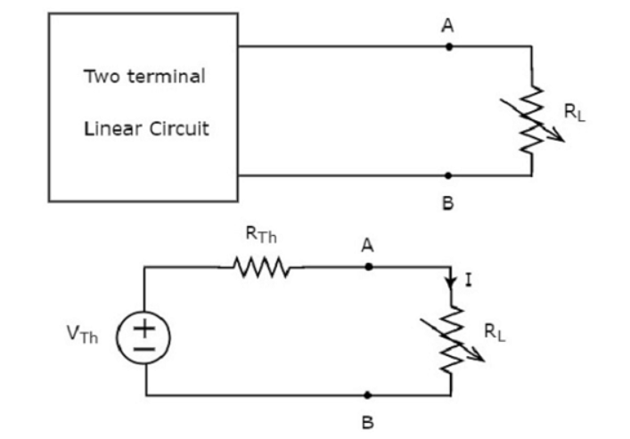
The amount of power dissipated across the load resistor is
PL = I 2 R L ----------------------(1)
Substitute I = Vth / Rth + RL
PL = Vth / (Rth + RL ) 2 RL
PL = Vth 2 { RL / (RTH + RL) 2 ------------------------------(2)
Condition for Maximum Power Transfer
For maximum or minimum, first derivative will be zero. So, differentiate Equation 1 with respect to RL and make it equal to zero.
DPL / d RL = V Th 2 { (Rth + RL) 2 x 1 -RL x 2(Rth + RL) / (Rth + RL) 4 } =0
(Rth + RL) 2 – 2RL (Rth + RL) = 0
(Rth + RL) (Rth + RL – 2 RL) = 0
Rth - RL = 0
Rth = RL or RL = Rth
Therefore, the condition for maximum power dissipation across the load is RL=RTh. That means, if the value of load resistance is equal to the value of source resistance that is Thevenin’s resistance, then the power dissipated across the load will be of maximum value.
Substitute RL = Rth and PL = PL,max
PL,max = V th 2 { Rth / (Rth + Rth ) 2 }
= V th 2 ( Rth / 4 Rth 2 )
= V th 2 / 4 Rth
PL,max = V th 2 / 4 RL [RL = Rth]
Efficiency of Maximum power transfer
 = PL,max/ Ps
PL,max = maximum amount of power transferred to the load
Ps = amount of power generated by the source.
The amount of power generated by the source is
Ps = I2 Rth + I2 RL
Ps = 2 I2 Rth ; since RL = Rth
Substitute I = Vth / 2 Rth
Ps = 2(Vth / 2Rth) 2 Rth
Ps = 2(Vth / 4Rth) 2 Rth
Ps = Vth 2 / 2 Rth
Substituting with PL max and Ps
 = (Vth 2 / 4 Rth) / (Vth 2 / 2 Rth)
 max = ½
Problem:
Find the maximum power that can be delivered to the load resistor RL of the circuit shown in the following figure.

Step 1 – Using Thevenin’s circuit we get
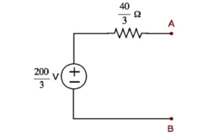
Thevenin’s voltage Vth = 200/3 and Thevenin’s resistance Rth = 40/3
Step 2 – Replace the left side of terminals A & B of the given circuit with the above Thevenin’s equivalent circuit. The resultant circuit diagram will be
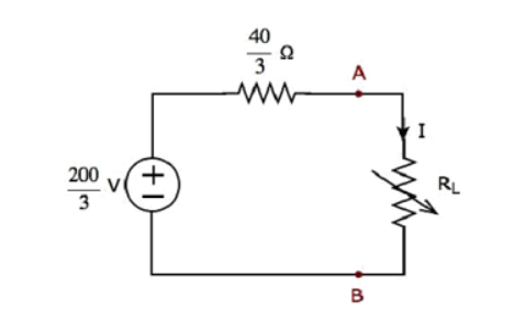
Step 3 − We can find the maximum power that will be delivered to the load resistor, RL by using the following formula.
P L,max = Vth 2 / 4 Rth
Substitute VTh=200/3 and RTh=40/3Ω
P L,max = (200/3) 2 / 4 (40/3)
Therefore, the maximum power that will be delivered to the load resistor RL of the given circuit is 250/3 .
Problem:
For the circuit shown find the value of RL that absorbs maximum power from the circuit and the corresponding power under this condition.
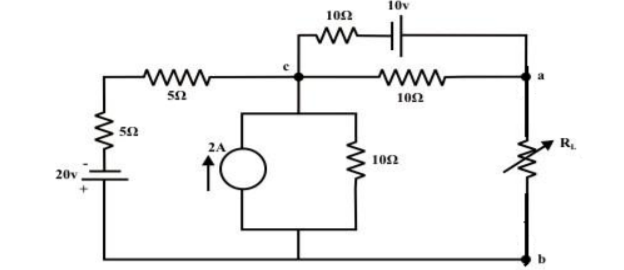
Load resistance RL is disconnected from the terminals ‘a’ and ‘b’ and the corresponding circuit diagram.
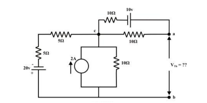
The above circuit is equivalently represented by a Thevenin circuit and the corresponding Thevenin voltage VTh and Thevenin resistance RTh are calculated by following the steps given below:
Considering 20V only
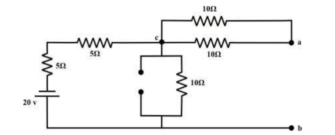
From the above circuit the current through ‘b-c’ branch =20/ 20 = 1𝐴 (𝑓𝑟𝑜𝑚 𝑎 𝑡𝑜 𝑏). Whereas the voltage across the ‘b-a’ branch vba =1 ×10 =10 volt . Since ’b’ is higher potential than ‘a’ ∴vab = − 10volt.
Considering only 10v source only
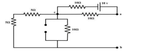
No current is flowing through ‘cb’-branch. Vab = 5v (‘a’ is higher potential than ‘b’). Consider only 2 A current source only
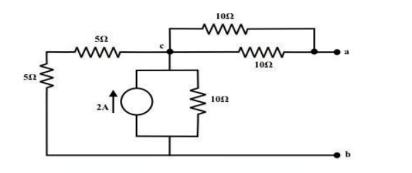
To compute Rth
Replace all voltage and current sources by their internal resistance of the circuit.
Rth = Rab = ((5+5)||10) + (10||10) = 5+5 =10Ω
RL = Rth = 10Ω
The maximum power dissipated to RL is
Pmax = Vth 2 / 4 Rth = ¼ 25 /10 = 0.625 watts
The reciprocity theorem states that in a linear passive bilateral network by changing the voltage source from branch 1 to branch2, the current I in the branch 2 appears in branch 1.

The resistances R1, R2 and R3 is connected in the circuit diagram. It is clearly shown the voltage and current sources are interchanged for solving the network.
Step 1 – Firstly, select the branches between which reciprocity is established.
Step 2 – The current in the branch is obtained using any conventional network analysis method.
Step 3 – The voltage source is interchanged between the branch which is selected.
Step 4 – The current in the branch where the voltage source was existing earlier is calculated.
Step 5 – Hence it is seen that the current obtained in the previous connection, that is step 2 and the current which is calculated when the source is interchanged, that is step 4 are identical to each other.
Problem:
Verify the reciprocity theorem for the given network.
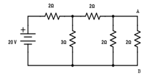
Find the current in branch AB
RT = 2+[3||(2 + 2 || 2)
RT = 3.5 Ω
IT = V / RT = 20/3.5 = 5.71 A
Apply current division technique for the circuit to find the current through branch AB
= 5.71 x 3 / 6 = 2.855 A
Current in branch AB = 2.855 x 2/4 = 1.43A
Interchanging the source to branch AB
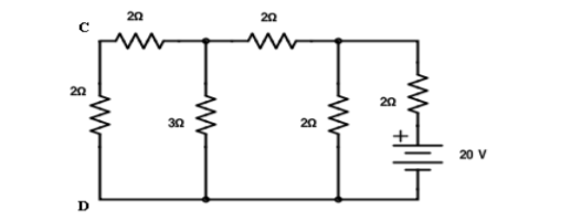
Total resistance RT = 3.23Ω IT = 20/3.23 = 6.19A
Apply current division technique for the circuit to find current through branch CD = 6.19 x 2/5.2 = 2.38A
Current in branch CD = 2.38 x 3/5 = 1.43A
Hence reciprocity theorem verified.
Verify the reciprocity theorem for the given circuit:
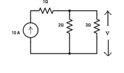
Apply current division technique for the circuit to find current through branch 3Ω
= 10 x 2 / 5 = 4 A.
Voltage across 3Ω = 4 x 3 = 12 V
Replace the current source and find the open circuit voltage.
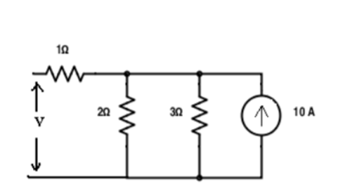
Apply current division technique and find the current through 2 Ω resistor.
= 10 x 3 / 5 = 6
Voltage across 2Ω resistor = voltage across AB = 6 x 2 = 12 V
This theorem states that in a linear time-invariant network when the resistance R of an uncoupled branch carrying current I is changed by ∆R then the currents would change which can be obtained by assuming that an ideal voltage source VC has been connected such that Vc = I ∆R in series with (R + ∆R) when all other sources in the network are replaced by their internal resistances.
Let us assume a load RL be connected to a DC source network whose Thevenin’s equivalent gives V0 as the Thevenin’s voltage and RTH as the Thevenin’s resistance as shown in the figure below:
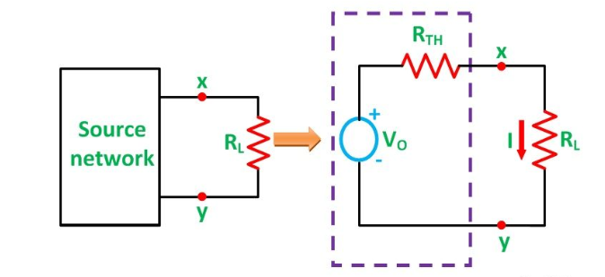
Here,
I = Vo / Rth + RL ------------------------------------(1)
Let the load resistance RL be changed to (RL + ΔRL).
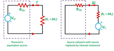
Here,
I ‘ = Vo/ Rth + (RL + ∆ RL) ------------------------(2)
The change of current is ∆I
Therefore,
∆I = I’ – I -------------------------------------(3)
Putting the value of I’ and I from the equation (1) and (2) in equation(3) we get
∆I = Vo / Rth + (RL + ∆ RL) - Vo / Rth + RL --------------------------(4)
∆I = Vo {Rth +RL – (Rth + RL + ∆ RL )} / (Rth + RL + ∆RL ) (Rth + RL)
∆I = - [ Vo/Rth + RL] ∆ RL / Rth + RL + ∆ RL -------------------------------------------------(5)
Now, putting the value of I from the equation (1) in equation (5), we will get the following equation:
∆I = - I ∆ RL / Rth + RL + ∆ RL ------------------------------------------------(6)
VC = I ΔRL and is known as compensating voltage.
∆I = -Vc / Rth + RL + ∆ RL
Hence, Compensation theorem states that the change of branch resistance, results a change in branch currents and the change is equivalent to an ideal compensating voltage source in series with the branch opposing the original current, where all other sources in the network being replaced by their internal resistances.
Problem :

For the circuit as shown in figure. Calculate current I3 . Let the value of resistance change by small value. Calculate the change in current I3.
Vs = 50V, R1 = 4 Ω, R2 = 15 Ω, R3 = 10 Ω, ∆R3 = 5Ω.
I3 = Vs R2/ R1.R2 + R2R3+ R1.R3 = 3A
Vc = (I3 ∆ R3) = 50 V
∆ I3 = -Vc / (R3 + ∆ R3) + R1. R2 / R1 + R2 = -19/23 A
Dependent current source
Dependent current source changes its available current depending upon the voltage across, or the current through, and some other element connected to the circuit.
That is the output of a dependent current source is controlled by another voltage or current.
A current source that depends on a voltage input is generally referred to as a Voltage Controlled Current Source or VCCS. A current source that depends on a current input is generally referred as a Current Controlled Current Source or CCCS.
Dependent Current Source Symbols

A voltage source that depends on a voltage input is generally referred to as a Voltage Controlled Voltage Source or VCVS. A voltage source that depends on a current input is referred as a Current Controlled Voltage Source or CCVS.
Ideal dependent sources are commonly used in the analysing the input/output characteristics or the gain of circuit elements such as operational amplifiers, transistors and integrated circuits.

An ideal dependent voltage-controlled current source, VCCS, maintains an output current, IOUT that is proportional to the controlling input voltage, VIN.
That is the output current “depends” on the value of input voltage making it a dependent current source. Then, the VCCS output current is defined by
IOUT = α VIN.
This multiplying constant α has the SI units of mhos, ℧ because α = IOUT/VIN, and its units will therefore be amperes/volt.
Nodal analysis
In the nodal method we are finding the node voltages with the following steps:
- Select a reference node. Assign all the rest nodes voltages , with respect to reference node.
- Use Kirchhoff’s and Ohm’s Laws to each non-reference node and branch currents.
- Resolve the system of equations and obtain node voltages.
Consider the following circuit.
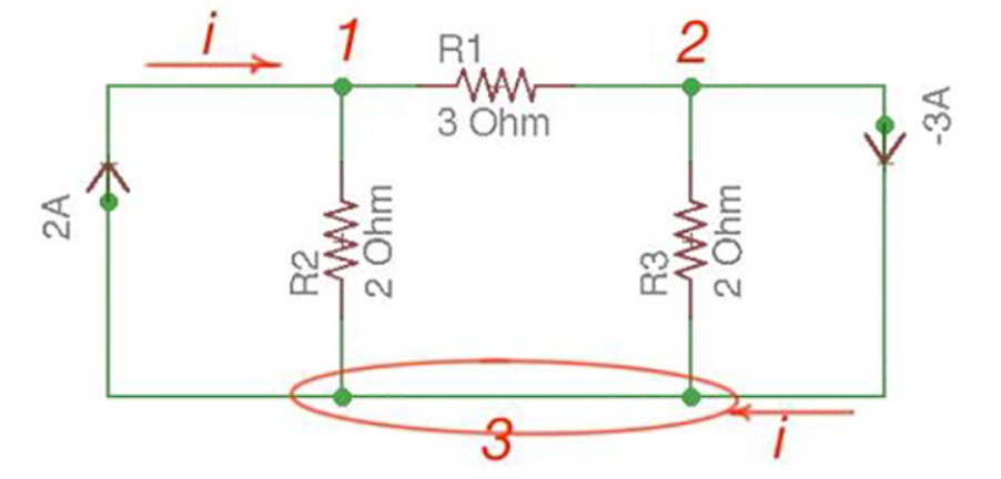
Let us consider a reference node – 3.
In a real circuit a reference node is ground is assumed to have potential.
By the Kirchhoff’s Law having the following current relation:
I1 = i1 + i2
I2 = i2 -i3
Let us represent currents like ratio of voltage and resistance by the Ohm’s Law:
i 1 = v1 /R1 ; i 2 = v1 -v2 /R2 ; i3 = v2/R3;
Or
i 1= v1 * G1 ; i2 =(v1 -v2)*G2 ; i3 =v2 * G3
i1 = v1 * G1 + (v1-v2) * G2 ;
i2 = (v1-v2) * G2 – v2 * G3
i1= v1 * (G1 +G2) – v2 * G2
i2 = v1 *G2 – v2 *(G3 +G2)
Or
And we achieve the following matrix equation, which can be resolved by the Cramer’s rule:
[ G1 + G2 -G3 -G3 ] [v1] = [I1]
[ G2 -G2][v2] =[I2]
Consider the following figure :
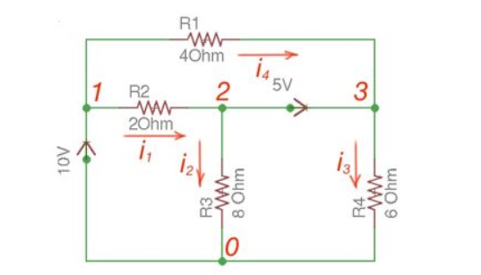
There are two possibilities that exist:
- If the voltage source is between reference node and non-reference node, the non-reference voltage is considered equal to the voltage source.
- If the voltage source is between two non-reference nodes, these two nodes are generalised nodes. To determine its voltage Kirchhoff’s Laws must be applied.
Applying Kirchhoff’s Law we achieve the following equations:
i 1 + i4 = i2 + i3
-v2 +5+v3 =0
v 1 =10
By Ohm’s Law
These equations will help determine node voltages.
Mesh Analysis
Mesh analysis is applicable to the networks which are planar. Planar network is a network where branches are not passing over or under each other.
Nodal method uses Kirchhoff’s currents Law to consider nodal voltages, and Mesh method uses Kirchhoff’s voltages Law to consider mesh currents. Mesh is a loop, which does not contain any other loops.
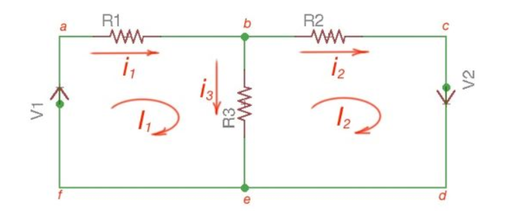
There are only two meshes in abefa and bcdeb, abcdefa is not a mesh but a loop However, for Mesh method only meshes are in use.
Mesh analysis steps are the following:
- Assign mesh currents to all the meshes in a circuit.
- Apply Kirchhoff’s voltage Law to each mesh. Apply Ohm’s Law to determine voltages with mesh currents.
- To resolve simultaneously all the equations to consider mesh currents.
The following equations correspond to the Kirchhoff’s Voltage Laws for the meshes:
V1 = i1 *(R1+R3) – i2 *R3
-V2 = -i1 *R3 + i2 * (R3 +R2);
[ R1 +R3 -R3 [i1]= [V1]
-R3 R2+R3] [i2] = [V2]
Using Cramer’s formula for resolving the matrix equations above we can find mesh currents.
I1 =i 1 I2 = i2 I1 -I2 =i3
Find the current flowing through 20 Ω resistor of the following circuit using Nodal analysis.

Step 1 − There are three principle nodes in the above circuit. Those are labelled as 1, 2, and 3 in the following figure. In the above figure, consider node 3 as reference node (Ground).

Step 2 − The node voltages, V1 and V2, are labelled in the following figure.
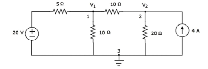
Step 3 – There are two nodal equations, since there are two principal nodes, 1 and 2, other than Ground.
The nodal equation at node 1 is
V1 -20/5 + V1/10 + V1-V2/10 =0
2V1 -40 +V1+V1-V2/10 =0
4V1 -40-V2 =0 --- V2 = 4V1-40 -------(1)
The nodal equation at node 2 is
-4 +V2/20 + V2-V1/10 =0
-80 + V2 + 2 V2 – 2V2/ 20 =0
= 3V2 -2V1 =80 --------------(2)
Step 4 − Finding node voltages, V1 and V2 by solving Equation 1 and Equation 2.
Substitute Equation 1 in Equation 2.
3(4V1−40)−2V1=80
⇒12V1−120−2V1=80
⇒10V1=200
⇒V1=20V
Substitute V1 = 20 V in Equation1.
V2=4(20)−40
⇒V2=40V
So, we got the node voltages V1 and V2 as 20 V and 40 V respectively.
Step 5 − The voltage across 20 Ω resistor is nothing but the node voltage V2 and it is equal to 40 V. Now, we can find the current flowing through 20 Ω resistor by using Ohm’s law.
I 20Ω = V2/R
Substitute the values of V2 and R
I 20 Ω = 40/20
I 20Ω = 2A
Therefore, the current flowing through the 20Ω resistor is 2A.
Find the voltage across 30 Ω resistor using Mesh analysis.

Step 1 − There are two meshes in the above circuit. The mesh currents I1 and I2 are considered in clockwise direction. These mesh currents are shown in the following figure.

Step 2 − The mesh current I1 flows through 20 V voltage source and 5 Ω resistor. Similarly, the mesh current I2 flows through 30 Ω resistor and -80 V voltage source. But, the difference of two mesh currents, I1 and I2, flows through 10 Ω resistor, since it is the common branch of two meshes.
Step 3 − Since there are two meshes in the given circuit write the mesh equations, assume the mesh current of that particular mesh as greater than all other mesh currents of the circuit.
The mesh equation of first mesh is
20−5I1−10(I1−I2)=0
⇒20−15I1+10I2=0
⇒10I2=15I1−20
Divide the above equation with 5.
2I2=3I1−4
Multiply the above equation with 2.
4I2=6I1−8-----------------(1)
The mesh equation of second mesh is
−10(I2−I1)−30 I2+80=0
Divide the above equation with 10.
−(I2−I1)−3I2+8=0
⇒−4I2+I1+8=0-----------------(2)
4I2 = I1 +8
Step 4 − Finding mesh currents I1 and I2 by solving Equation 1 and Equation 2.
The left-hand side terms of Equation 1 and Equation 2 are the same. Hence, equate the right-hand side terms of Equation 1 and Equation 2 in order find the value of I1.
6I1 -8 = I1 +8
5I1 =16
I1 = 16/5 A
Hence, 4I2 = 16/5 + 8
4I2 = 56/5
I2 = 56/20 = 2.8 A
Step 5 − The current flowing through 30 Ω resistor is nothing but the mesh current I2 and it is equal to 14/5 A. The voltage across 30 Ω resistor by using Ohm’s law.
V 30 Ω = I2 R
V30Ω = (14/5) x 30 = 84V
Dual Network:
Two electrical networks are said to be dual networks if the mesh equation of one network is equal to the node equation of other.
The dual network is based on Kirchhoff Current Law and Kirchhoff Voltage Law.
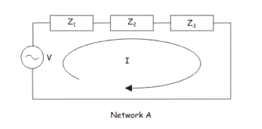
Applying Kirchhoff Voltage law in the network A we get
V = IZ1 + I Z2 + I Z3
V = I( Z1 + Z2 + Z3)-----------------------(1)
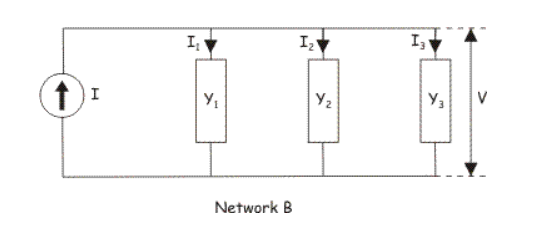
Applying Kirchhoff Current Law in network B we get
I = I1 + I2 + I3
I = VY1 + V Y2 + V Y3
I = V (Y1 + Y2 + Y3)-----------------------(2)
Equation (i) and (ii) are similar in their mathematical form. Equation (i) is in mesh form and equation (ii) is in nodal form.
Construction of Dual Network
Consider series RLC circuit as shown
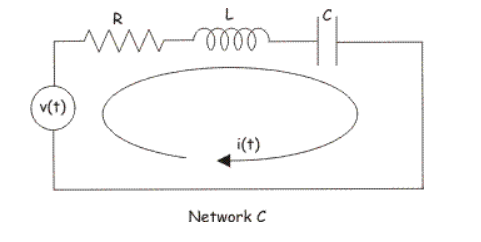
Applying Kirchhoff Voltage law in the circuit we get

Let us replace all the variables and constants by their dual in the equation. By doing that, we get,

The electrical network drawn by the circuit equation would be
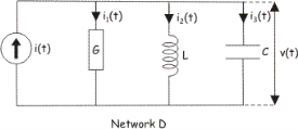
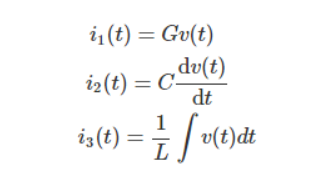

This is nothing but Kirchhoff’s current law.
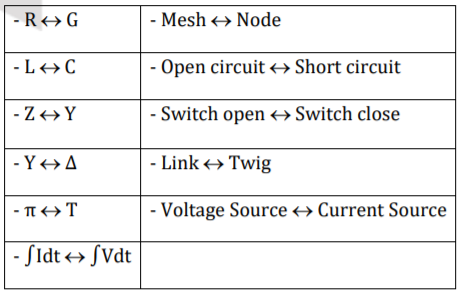
As per definition of dual network, the network C and network D are dual to each other.
Element | Element |
Electrical Resistance | Conductance |
Inductance | Capacitance |
Mesh | Node |
Switch Closed | Switch Open |
Charge | Flux Linkage |
Duality
Identical behaviour patterns observed between voltages and currents in two circuits illustrate the principal of duality.
Steps:
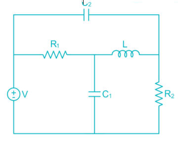
1. Inside each loop place a node and give it a number for all loops for convenience, place an extra node, the reference node, external to the network say ‘O’ node. Place an extra the same numbered nodes on a separate space on the paper for the construction of the dual.
2. Draw a line between two nodes of the original network traversing only one element at a time. Thus, draw Lines from node to node through the elements in the original network. For each element traversed in the original network, connect the dual elements from the Listing just given on dual network being constructed.
3. Continue this process unit the number of possible paths through single elements is exhausted. If we go through a connecting lead assumed to be a short, the dual elements is an open circuit.
4. The network so constructed is a dual network.
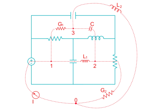
The dual network is
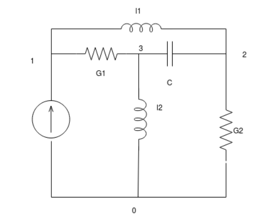
The voltage source in the original network are replace by the current sources in the dual network and vice – versa. The most important task is to decide the orientation of these sources in the dual network, it is determined as follows.
- Initially, we assume a clockwise direction for all mesh currents in original network N1. Each mesh current enclosing a dot (node) of the dual network say N2.
2. It is important to note that the orientation of the voltage source is identified with the direction of the mesh current whereas the orientation of the current source is identified with the node which is enclosed by mesh current.
3. If the direction of the voltage source and clockwise mesh current is same in the network N1, then the orientation of the current source in the dual network N2 is towards the node which is enclosed by the said mesh current in N1.
4. Conversely if the directions of the voltage source and the clock wise mesh current are opposite then the current of the current source in N2 is directed away from the node which is enclosed by the said mesh current in N1.
Example 2.
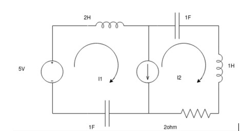
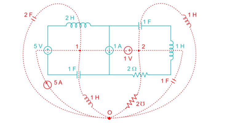
The dual network is
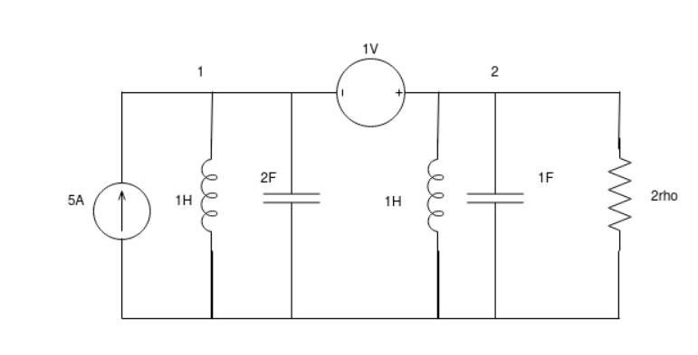
References:
- Network theory by A.V Bakshi, U.A Bakshi
- Network Theory Analysis and Synthesis by Smarajit Ghosh
- Networks: An introduction by Mark Newman
- Network Theory (Bput) book by Satpathy